2001 INFINITI QX4 Battery cables
[x] Cancel search: Battery cablesPage 2110 of 2395

SRS162
4. Install instrument lower panel on passenger side.
5. Connect air bag module connector to air bag harness connec-
tor.
6. Install glove box assembly.
7. Connect both battery cables.
8. Conduct self-diagnosis to ensure entire SRS operates prop-
erly. (Use CONSULT-II or warning lamp check.)
SRS682
Side Air Bag Module
REMOVALNBRS0036CAUTION:
IBefore servicing SRS, turn the ignition switch OFF, dis-
connect both battery cables and wait at least 3 minutes.
IAlways work from the rear of the air bag module.
1. Remove seatback board.
IWhen using a clip removal tool to remove the seatback
board, take care not to damage the air bag harness.
2. Disconnect side air bag module connector by sliding tab.
SRS683
3. Pull up the seatback trim.
4. Remove the nuts securing the inner cloth with seatback frame.
Then pull up the inner cloth.
5. Remove seatback trim. Refer to BT-41, ªFRONT SEATº for
details.
SRS684
6. Remove the torx nuts coated with bonding agent from the side
air bag module.
7. Remove side air bag connector. Side air bag module can then
be removed.
SRS623
CAUTION:
IAlways place the air bag module stading with the stud bolt
side setting bottom.
IDo not attempt to disassemble air bag module.
IThe torx nuts are coated with bonding agent. Do not use
old nuts after removal; replace with new coated nuts.
IDo not insert any foreign objects (screwdriver, etc.) into
air bag module connector.
GI
MA
EM
LC
EC
FE
AT
TF
PD
AX
SU
BR
ST
BT
HA
SC
EL
IDX
SUPPLEMENTAL RESTRAINT SYSTEM (SRS)
Front Passenger Air Bag Module (Cont'd)
RS-21
Page 2111 of 2395

SBF814E
IReplace air bag module if it has been dropped or sus-
tained an impact.
IDo not expose the air bag module to temperatures exceed-
ing 90ÉC (194ÉF).
IDo not allow oil, grease or water to come in contact with
the air bag module.
IAfter air bag inflates, all parts of front seatback (including
front seatback frame) should be replaced.
SRS684
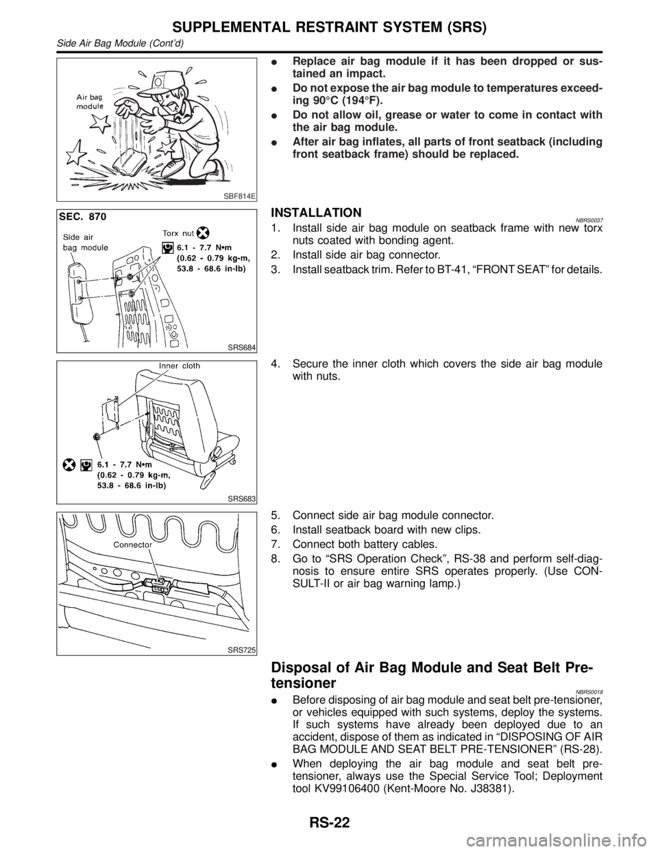
INSTALLATIONNBRS00371. Install side air bag module on seatback frame with new torx
nuts coated with bonding agent.
2. Install side air bag connector.
3. Install seatback trim. Refer to BT-41, ªFRONT SEATº for details.
SRS683
4. Secure the inner cloth which covers the side air bag module
with nuts.
SRS725
5. Connect side air bag module connector.
6. Install seatback board with new clips.
7. Connect both battery cables.
8. Go to ªSRS Operation Checkº, RS-38 and perform self-diag-
nosis to ensure entire SRS operates properly. (Use CON-
SULT-II or air bag warning lamp.)
Disposal of Air Bag Module and Seat Belt Pre-
tensioner
NBRS0018IBefore disposing of air bag module and seat belt pre-tensioner,
or vehicles equipped with such systems, deploy the systems.
If such systems have already been deployed due to an
accident, dispose of them as indicated in ªDISPOSING OF AIR
BAG MODULE AND SEAT BELT PRE-TENSIONERº (RS-28).
IWhen deploying the air bag module and seat belt pre-
tensioner, always use the Special Service Tool; Deployment
tool KV99106400 (Kent-Moore No. J38381).
SUPPLEMENTAL RESTRAINT SYSTEM (SRS)
Side Air Bag Module (Cont'd)
RS-22
Page 2116 of 2395

SRS662
DEPLOYMENT PROCEDURES FOR SEAT BELT PRE-
TENSIONER (OUTSIDE OF VEHICLE)
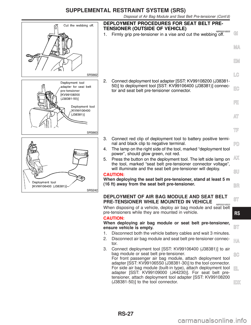
NBRS0018S051. Firmly grip pre-tensioner in a vise and cut the webbing off.
SRS663
2. Connect deployment tool adapter [SST: KV99108200 (J38381-
50)] to deployment tool [SST: KV99106400 (J38381)] connec-
tor and seat belt pre-tensioner connector.
SRS242
3. Connect red clip of deployment tool to battery positive termi-
nal and black clip to negative terminal.
4. The lamp on the right side of the tool, marked ªdeployment tool
powerº, should glow green, not red.
5. Press the button on the deployment tool. The left side lamp on
the tool, marked ªseat belt pre-tensioner connector voltageº,
will illuminate and the seat belt pre-tensioner will deploy.
CAUTION:
When deploying the seat belt pre-tensioner, stand at least 5 m
(16 ft) away from the seat belt pre-tensioner.
DEPLOYMENT OF AIR BAG MODULE AND SEAT BELT
PRE-TENSIONER WHILE MOUNTED IN VEHICLE
NBRS0018S03When disposing of a vehicle, deploy air bag module and seat belt
pre-tensioners while they are mounted in vehicle.
CAUTION:
When deploying air bag module or seat belt pre-tensioner,
ensure vehicle is empty.
1. Disconnect both the vehicle battery cables and wait 3 minutes.
2. Disconnect air bag module and seat belt pre-tensioner connec-
tor.
3. Connect deployment tool [SST: KV99106400 (J38381)] to air
bag module or seat belt pre-tensioner.
For front passenger air bag module, attach deployment tool
adapter [SST: KV991065S0 (J38381-30)] to the tool connector.
For side air bag module (built-in type), attach deployment tool
adapter [SST: KV99109000 (J44230)]. For seat belt pre-
tensioner, attach deployment tool adapter [SST: KV99108200
(J38381-50)] to the tool connector.
GI
MA
EM
LC
EC
FE
AT
TF
PD
AX
SU
BR
ST
BT
HA
SC
EL
IDX
SUPPLEMENTAL RESTRAINT SYSTEM (SRS)
Disposal of Air Bag Module and Seat Belt Pre-tensioner (Cont'd)
RS-27
Page 2129 of 2395
![INFINITI QX4 2001 Factory Service Manual SRS701
If no malfunction is detected on ªSELF-DIAG [CURRENT]º even
though malfunction is detected in ªSRS Operation Checkº, check
the battery voltage.
If the battery voltage is less than 9V, charg INFINITI QX4 2001 Factory Service Manual SRS701
If no malfunction is detected on ªSELF-DIAG [CURRENT]º even
though malfunction is detected in ªSRS Operation Checkº, check
the battery voltage.
If the battery voltage is less than 9V, charg](/manual-img/42/57027/w960_57027-2128.png)
SRS701
If no malfunction is detected on ªSELF-DIAG [CURRENT]º even
though malfunction is detected in ªSRS Operation Checkº, check
the battery voltage.
If the battery voltage is less than 9V, charge the battery. Then go
to DIAGNOSTIC PROCEDURE 3, page RS-42.
If the battery voltage is OK, go to DIAGNOSTIC PROCEDURE 4,
page RS-44, to diagnose the following cases:
ISelf-diagnostic result ªSELF-DIAG [PAST]º (previously stored
in the memory) might not be erased after repair.
IThe SRS system malfunctions intermittently.
8. Touch ªPRINTº.
9. Compare diagnostic codes to ªCONSULT-II Diagnostic Code
Chartº, page RS-40.
10. Touch ªBACKº key of CONSULT-II until ªSELECT SYSTEMº
appears in order to return to User mode from Diagnosis mode.
11. Turn ignition switch ªOFFº, then turn off and disconnect
CONSULT-II, and disconnect both battery cables.
12. Repair the system as outlined by the ªRepair orderº in ªCON-
SULT-II Diagnostic Code Chartº, that corresponds to the self-
diagnostic result. For replacement procedure of component
parts, refer to RS-15.
13. After repairing the system, go to DIAGNOSTIC PROCEDURE
3, page RS-42 for final checking.
CONSULT-II Diagnostic Code Chart (ªSELF-DIAG
[CURRENT]º)
NBRS0045S0101
Diagnostic item ExplanationRepair order
ªRecheck SRS at each replace-
ment.º
NO DTC IS
DETECTED.When malfunction is
indicated by the ªAIR
BAGº warning lamp in
User modeILow battery voltage (Less than 9V)IGo to DIAGNOSTIC PROCEDURE 3
(RS-42) after charging battery.
ISelf-diagnostic result ªSELF-DIAG
[PAST]º (previously stored in the
memory) might not be erased after
repair.
IIntermittent malfunction has been
detected in the past.IGo to DIAGNOSTIC PROCEDURE 4
(RS-44).
INo malfunction is detected.IGo to DIAGNOSTIC PROCEDURE 3
(RS-42).
AIRBAG MODULE
[OPEN]IDriver's air bag module circuit is open. (including the spiral
cable)1. Visually check the wiring harness
connection.
2. Replace the harness if it has visible
damage.
3. Replace driver's air bag module.
(Before disposal of it, it must be
deployed.)
4. Replace the spiral cable.
5. Replace the diagnosis sensor unit.
6. Replace the related harness.
SUPPLEMENTAL RESTRAINT SYSTEM (SRS)
Trouble Diagnoses with CONSULT-II (Cont'd)
RS-40
Page 2131 of 2395
![INFINITI QX4 2001 Factory Service Manual Diagnostic item ExplanationRepair order
ªRecheck SRS at each replace-
ment.º
PRE-TEN FRONT LH
[OPEN/VB-SHORT]IThe circuit for front LH pre-tensioner is open or shorted to
some power supply circuit.1 INFINITI QX4 2001 Factory Service Manual Diagnostic item ExplanationRepair order
ªRecheck SRS at each replace-
ment.º
PRE-TEN FRONT LH
[OPEN/VB-SHORT]IThe circuit for front LH pre-tensioner is open or shorted to
some power supply circuit.1](/manual-img/42/57027/w960_57027-2130.png)
Diagnostic item ExplanationRepair order
ªRecheck SRS at each replace-
ment.º
PRE-TEN FRONT LH
[OPEN/VB-SHORT]IThe circuit for front LH pre-tensioner is open or shorted to
some power supply circuit.1. Visually check the wiring harness
connections.
2. Replace the harness if it has visible
damage.
3. Replace front LH seat belt.
(Before disposing, it must be deacti-
vated.)
4. Replace the diagnosis sensor unit.
5. Replace the related harness. PRE-TEN FRONT LH
[GND-SHORT]IThe circuit for front LH pre-tensioner is shorted to ground.
PRE-TEN FRONT RH
[OPEN/VB-SHORT]IThe circuit for front RH pre-tensioner is open or shorted to
some power supply circuit.1. Visually check the wiring harness
connections.
2. Replace the harness if it has visible
damage.
3. Replace front RH seat belt.
(Before disposing, it must be deacti-
vated.)
4. Replace the diagnosis sensor unit.
5. Replace the related harness. PRE-TEN FRONT RH
[GND-SHORT]IThe circuit for front RH pre-tensioner is shorted to ground.
CONTROL UNITIDiagnosis sensor unit is malfunctioning. 1. Visually check the wiring harness
connection.
2. Replace the diagnosis sensor unit.
* Follow the procedures in numerical order when repairing malfunctioning parts. Confirm whether malfunction is eliminated
using the air bag warning lamp or CONSULT-II each time repair is finished. If malfunction is still observed, proceed to the next
step. When malfunction is eliminated, further repair work is not required.
SRS844
DIAGNOSTIC PROCEDURE 3NBRS0045S02Final checking after repairing SRS by using CONSULT-II Ð
Diagnosis mode
1. After repairing SRS, connect both battery cables.
2. Connect CONSULT-II to Data link connector.
3. Turn ignition switch from ªOFFº to ªONº.
SRS695
4. Touch ªSTARTº.
SUPPLEMENTAL RESTRAINT SYSTEM (SRS)
Trouble Diagnoses with CONSULT-II (Cont'd)
RS-42
Page 2135 of 2395

SRS704
9. Diagnostic code is displayed on ªTROUBLE DIAG RECORDº.
10. Touch ªPRINTº.
11. Compare diagnostic codes to ªIntermittent Malfunction Diag-
nostic Code Chartº, page RS-46.
12. Touch ªBACKº key of CONSULT-II until ªSELECT SYSTEMº
appears.
13. Turn ignition switch ªOFFº, then turn off and disconnect
CONSULT-II, and disconnect both battery cables.
14. Repair the system as outlined by the ªRepair orderº in ªInter-
mittent Malfunction Diagnostic Code Chartº, that corresponds
to the self-diagnostic result. For replacement procedure of
component parts, refer to RS-15.
15. Go to DIAGNOSTIC PROCEDURE 3, page RS-42, for final
checking.
Intermittent Malfunction Diagnostic Code Chart (ªSELF-
DIAG [PAST]º or ªTROUBLE DIAG RECORDº)
NBRS0045S0401
Diagnostic item Explanation Repair order
NO DTC IS
DETECTED.When malfunction is
indicated by the ªAIR
BAGº warning lamp in
User modeILow battery voltage (Less than 9V)IGo to DIAGNOSTIC PROCEDURE
3 (RS-42) after charging battery.
INo malfunction is detected.IGo to DIAGNOSTIC PROCEDURE
3 (RS-42).
AIRBAG MODULE
[OPEN]IDriver's air bag module circuit is open. (including the spiral
cable)1. Visually check the wiring harness
connection.
2. Replace the harness if it has visible
damage.
3. If the harness check result is OK,
replace driver's air bag module
(Before disposal of it, it must be
deployed.), diagnosis sensor unit
and spiral cable. AIRBAG MODULE
[VB-SHORT]IDriver's air bag module circuit is shorted to some power sup-
ply circuit. (including the spiral cable)
AIRBAG MODULE
[GND-SHORT]IDriver's air bag module circuit is shorted to ground. (including
the spiral cable)
AIRBAG MODULE
[SHORT]IDriver's air bag module circuits are shorted to each other.
ASSIST A/B MODULE
[VB-SHORT]IFront passenger air bag module circuit is shorted to some
power supply circuit.1. Visually check the wiring harness
connection.
2. Replace the harness if it has visible
damage.
3. If the harness check result is OK,
replace front air bag module
(Before disposal of it, it must be
deployed.), and diagnosis sensor
unit. ASSIST A/B MODULE
[OPEN]IFront passenger air bag module circuit is open.
ASSIST A/B MODULE
[GND-SHORT]IFront passenger air bag module circuit is shorted to ground.
ASSIST A/B MODULE
[SHORT]IFront passenger air bag module circuits are shorted to each
other.
SUPPLEMENTAL RESTRAINT SYSTEM (SRS)
Trouble Diagnoses with CONSULT-II (Cont'd)
RS-46
Page 2138 of 2395

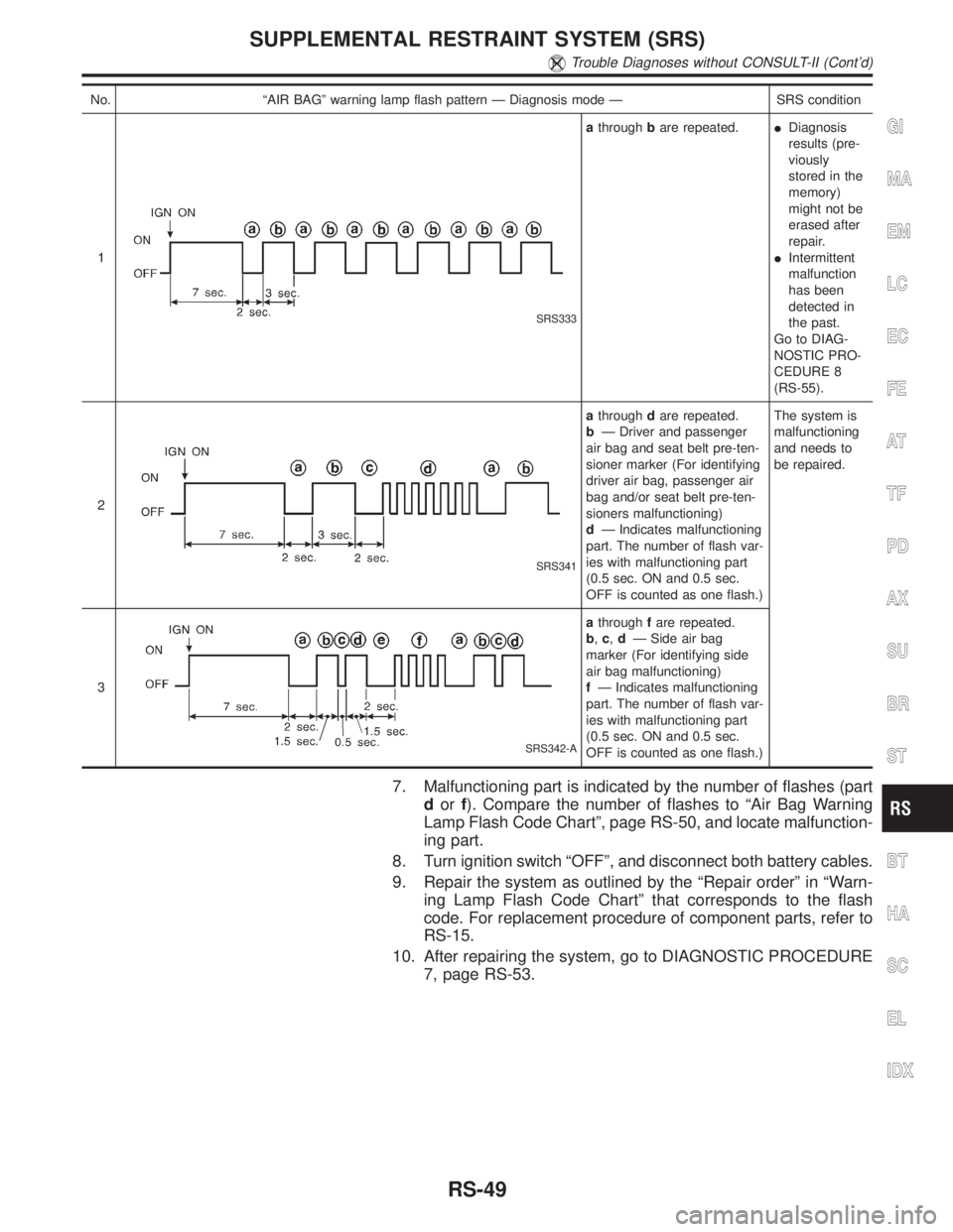
No. ªAIR BAGº warning lamp flash pattern Ð Diagnosis mode Ð SRS condition
1
SRS333
athroughbare repeated.IDiagnosis
results (pre-
viously
stored in the
memory)
might not be
erased after
repair.
IIntermittent
malfunction
has been
detected in
the past.
Go to DIAG-
NOSTIC PRO-
CEDURE 8
(RS-55).
2
SRS341
athroughdare repeated.
bÐ Driver and passenger
air bag and seat belt pre-ten-
sioner marker (For identifying
driver air bag, passenger air
bag and/or seat belt pre-ten-
sioners malfunctioning)
dÐ Indicates malfunctioning
part. The number of flash var-
ies with malfunctioning part
(0.5 sec. ON and 0.5 sec.
OFF is counted as one flash.)The system is
malfunctioning
and needs to
be repaired.
3
SRS342-A
athroughfare repeated.
b,c,dÐ Side air bag
marker (For identifying side
air bag malfunctioning)
fÐ Indicates malfunctioning
part. The number of flash var-
ies with malfunctioning part
(0.5 sec. ON and 0.5 sec.
OFF is counted as one flash.)
7. Malfunctioning part is indicated by the number of flashes (part
dorf). Compare the number of flashes to ªAir Bag Warning
Lamp Flash Code Chartº, page RS-50, and locate malfunction-
ing part.
8. Turn ignition switch ªOFFº, and disconnect both battery cables.
9. Repair the system as outlined by the ªRepair orderº in ªWarn-
ing Lamp Flash Code Chartº that corresponds to the flash
code. For replacement procedure of component parts, refer to
RS-15.
10. After repairing the system, go to DIAGNOSTIC PROCEDURE
7, page RS-53.
GI
MA
EM
LC
EC
FE
AT
TF
PD
AX
SU
BR
ST
BT
HA
SC
EL
IDX
SUPPLEMENTAL RESTRAINT SYSTEM (SRS)
Trouble Diagnoses without CONSULT-II (Cont'd)
RS-49
Page 2142 of 2395

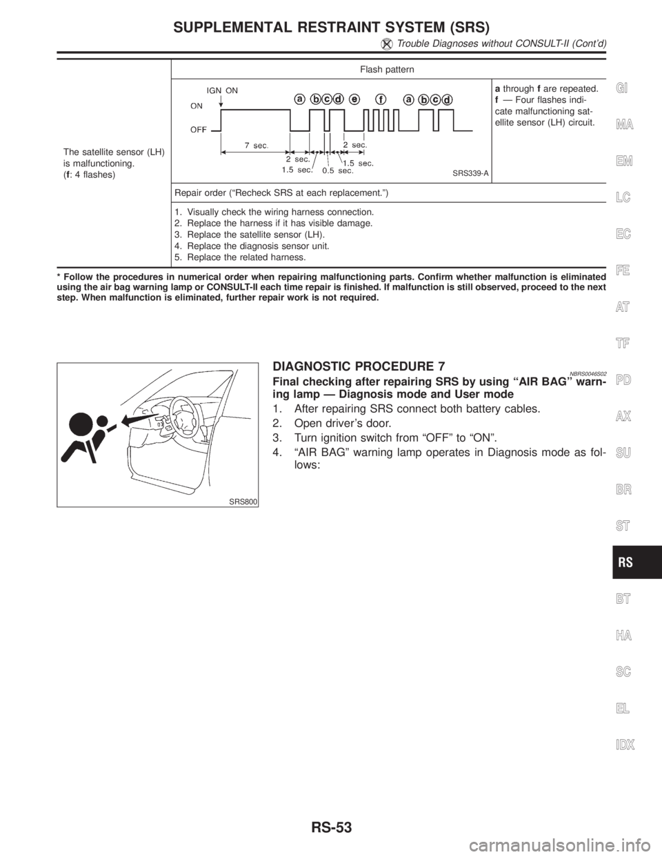
The satellite sensor (LH)
is malfunctioning.
(f: 4 flashes)Flash pattern
SRS339-A
athroughfare repeated.
fÐ Four flashes indi-
cate malfunctioning sat-
ellite sensor (LH) circuit.
Repair order (ªRecheck SRS at each replacement.º)
1. Visually check the wiring harness connection.
2. Replace the harness if it has visible damage.
3. Replace the satellite sensor (LH).
4. Replace the diagnosis sensor unit.
5. Replace the related harness.
* Follow the procedures in numerical order when repairing malfunctioning parts. Confirm whether malfunction is eliminated
using the air bag warning lamp or CONSULT-II each time repair is finished. If malfunction is still observed, proceed to the next
step. When malfunction is eliminated, further repair work is not required.
SRS800
DIAGNOSTIC PROCEDURE 7NBRS0046S02Final checking after repairing SRS by using ªAIR BAGº warn-
ing lamp Ð Diagnosis mode and User mode
1. After repairing SRS connect both battery cables.
2. Open driver's door.
3. Turn ignition switch from ªOFFº to ªONº.
4. ªAIR BAGº warning lamp operates in Diagnosis mode as fol-
lows:
GI
MA
EM
LC
EC
FE
AT
TF
PD
AX
SU
BR
ST
BT
HA
SC
EL
IDX
SUPPLEMENTAL RESTRAINT SYSTEM (SRS)
Trouble Diagnoses without CONSULT-II (Cont'd)
RS-53