Page 2365 of 2395
SMT924C
7. Remove 4WD solenoid valve, clutch pressure switch, 2-4WD
shift solenoid valve, line pressure switch, and transfer fluid
temperature sensor from control valve assembly.
8. Remove O-rings from each solenoid valve, switch and termi-
nal body.
IDo not reuse O-rings.
SMT925C
9. Place control valve with lower body facing up, remove two
mounting bolts, and then remove lower body and separator
plate from upper body.
CAUTION:
IBe careful not to drop relief balls. Detach lower body care-
fully.
IDo not reuse separator plate.
SMT926C
10. Make sure reverse balls, relief balls and relief springs, accu-
mulator pistons, valve springs, and filters are securely installed
as shown in the figure, and remove them.
SMT927C
11. Remove retainer plates.
SMT928CA
12. Remove each control valve, spring and plug.
DISASSEMBLY
Center Case (Cont'd)
TF-130
Page 2374 of 2395

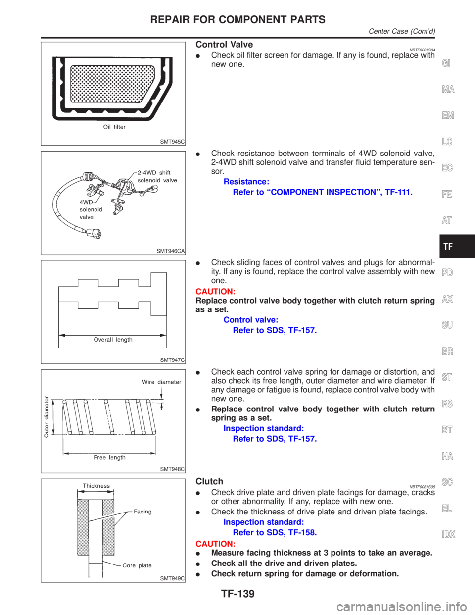
SMT945C
Control ValveNBTF0081S04ICheck oil filter screen for damage. If any is found, replace with
new one.
SMT946CA
ICheck resistance between terminals of 4WD solenoid valve,
2-4WD shift solenoid valve and transfer fluid temperature sen-
sor.
Resistance:
Refer to ªCOMPONENT INSPECTIONº, TF-111.
SMT947C
ICheck sliding faces of control valves and plugs for abnormal-
ity. If any is found, replace the control valve assembly with new
one.
CAUTION:
Replace control valve body together with clutch return spring
as a set.
Control valve:
Refer to SDS, TF-157.
SMT948C
ICheck each control valve spring for damage or distortion, and
also check its free length, outer diameter and wire diameter. If
any damage or fatigue is found, replace control valve body with
new one.
IReplace control valve body together with clutch return
spring as a set.
Inspection standard:
Refer to SDS, TF-157.
SMT949C
ClutchNBTF0081S05ICheck drive plate and driven plate facings for damage, cracks
or other abnormality. If any, replace with new one.
ICheck the thickness of drive plate and driven plate facings.
Inspection standard:
Refer to SDS, TF-158.
CAUTION:
IMeasure facing thickness at 3 points to take an average.
ICheck all the drive and driven plates.
ICheck return spring for damage or deformation.
GI
MA
EM
LC
EC
FE
AT
PD
AX
SU
BR
ST
RS
BT
HA
SC
EL
IDX
REPAIR FOR COMPONENT PARTS
Center Case (Cont'd)
TF-139
Page 2382 of 2395

SMT928C
SMT926C
Control ValveNBTF0083S041. Clean upper body, control valves and springs with cleaning
agent, and apply air blow.
2. Dip control valves in ATF, and apply ATF to the valve-mount-
ing area of upper body.
3. Install each control valve, spring, and plug to upper body, and
fix it with retainer plates.
CAUTION:
ITo insert control valves into upper body, place upper body
on a level surface in order to prevent flaw or damage.
IMake sure each control valve is smoothly inserted.
4. Install reverse balls, relief balls and relief springs, accumula-
tor pistons, valve springs and two filters to upper body.
SMT925C
5. Install lower body and separator plate to upper body.
IDo not reuse separator plates.
SMT962CA
6. With lower body down, tighten two bolts in the position shown
in the figure.
7. Apply ATF or petroleum jelly to new O-ring, and install it to
2-4WD shift solenoid valve, terminal body, line pressure switch
and 4WD solenoid valve. Install them to control valve assem-
bly.
IDo not reuse O-rings.
SMT922CA
8. Apply ATF or petroleum jelly to lip seals, and install them to
center case.
IDo not reuse lip seals.
IThere are 2 kinds of lip seals (lip seal of large inner diam-
eter: 5 pieces, lip seal of small inner diameter: 2 pieces).
Confirm the position before installation.
GI
MA
EM
LC
EC
FE
AT
PD
AX
SU
BR
ST
RS
BT
HA
SC
EL
IDX
ASSEMBLY
Center Case (Cont'd)
TF-147