2001 INFINITI QX4 warning
[x] Cancel search: warningPage 1754 of 2395
NBGI0002
IThe captionsWARNINGandCAUTIONwarn you of steps that must be followed to prevent personal injury
and/or damage to some part of the vehicle.
WARNINGindicates the possibility of personal injury if instructions are not followed.
CAUTIONindicates the possibility of component damage if instructions are not followed.
BOLD TYPED STATEMENTSexceptWARNINGandCAUTIONgive you helpful information.
IALPHABETICAL INDEXis provided at the end of this manual so that you can rapidly find the item and
page you are searching for.
IA QUICK REFERENCE INDEX, a black tab (e.g.
) is provided on the first page. You can quickly find
the first page of each section by mating it to the section's black tab.
ITHE CONTENTSare listed on the first page of each section.
ITHE TITLEis indicated on the upper portion of each page and shows the part or system.
ITHE PAGE NUMBERof each section consists of two letters which designate the particular section and a
number (e.g. ªBR-5º).
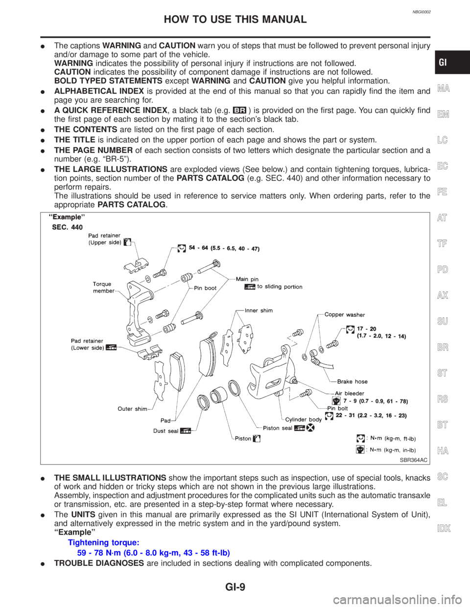
ITHE LARGE ILLUSTRATIONSare exploded views (See below.) and contain tightening torques, lubrica-
tion points, section number of thePARTS CATALOG(e.g. SEC. 440) and other information necessary to
perform repairs.
The illustrations should be used in reference to service matters only. When ordering parts, refer to the
appropriatePARTS CATALOG.
SBR364AC
ITHE SMALL ILLUSTRATIONSshow the important steps such as inspection, use of special tools, knacks
of work and hidden or tricky steps which are not shown in the previous large illustrations.
Assembly, inspection and adjustment procedures for the complicated units such as the automatic transaxle
or transmission, etc. are presented in a step-by-step format where necessary.
ITheUNITSgiven in this manual are primarily expressed as the SI UNIT (International System of Unit),
and alternatively expressed in the metric system and in the yard/pound system.
ªExampleº
Tightening torque:
59 - 78 N´m (6.0 - 8.0 kg-m, 43 - 58 ft-lb)
ITROUBLE DIAGNOSESare included in sections dealing with complicated components.
MA
EM
LC
EC
FE
AT
TF
PD
AX
SU
BR
ST
RS
BT
HA
SC
EL
IDX
HOW TO USE THIS MANUAL
GI-9
Page 1784 of 2395
Diagnostic
test modeFunction ENGINEALL-
MODE
4WDA/T ABSAIR
BAGIVCS*1IVIS
(NATS)*2SMART
EN-
TRANCE
Registered
dataDisplay the VIN, etc. data
registered in the IVCS
unit.ÐÐÐÐÐ x ÐÐ
Configura-
tionIThe IVCS system can
be set up in the dem-
onstration mode to
confirm system opera-
tion.
IVarious data related to
both the Communica-
tor Response Center
contract and cellular
provider can be
written/rewritten in this
mode.ÐÐÐÐÐ x ÐÐ
REMO
CONT ID
SET UPA maximum of four IDs
(identifications) can be
registered in the memory
using the remote control-
ler. These IDs can be
also be confirmed and
erased as required.ÐÐÐÐÐÐÐ x
x: Applicable
*1: INFINITI Communicator (IVCS)
*2: IVIS (NATS) [INFINITI Vehicle Immobilizer System (Nissan Anti-Theft System)]
Nickel Metal Hydride Battery ReplacementNBGI0006S06CONSULT-II contains a nickel metal hydride battery. When replacing the battery obey the following:
WARNING:
Replace the nickel metal hydride battery with Genuine CONSULT-II battery only. Use of another bat-
tery may present a risk of fire or explosion. The battery may present a fire or chemical burn hazard if
mistreated. Do not recharge, disassemble of dispose of in fire.
Keep the battery out of reach of children and discard used battery conforming to the local regulations.
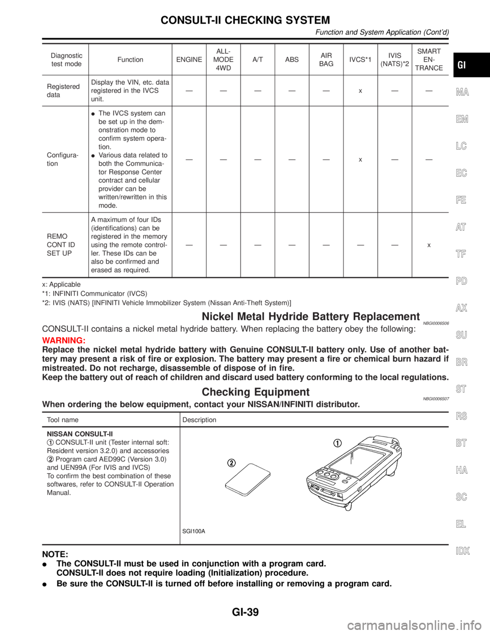
Checking EquipmentNBGI0006S07When ordering the below equipment, contact your NISSAN/INFINITI distributor.
Tool name Description
NISSAN CONSULT-II
q
1CONSULT-II unit (Tester internal soft:
Resident version 3.2.0) and accessories
q
2Program card AED99C (Version 3.0)
and UEN99A (For IVIS and IVCS)
To confirm the best combination of these
softwares, refer to CONSULT-II Operation
Manual.
SGI100A
NOTE:
IThe CONSULT-II must be used in conjunction with a program card.
CONSULT-II does not require loading (Initialization) procedure.
IBe sure the CONSULT-II is turned off before installing or removing a program card.
MA
EM
LC
EC
FE
AT
TF
PD
AX
SU
BR
ST
RS
BT
HA
SC
EL
IDX
CONSULT-II CHECKING SYSTEM
Function and System Application (Cont'd)
GI-39
Page 1790 of 2395
NBGI0008
WARNING:
INever get under the vehicle while it is supported only by
the jack. Always use safety stands to support the frame
when you have to get under the vehicle.
IPlace wheel chocks at both front and back of the wheels
on the ground.
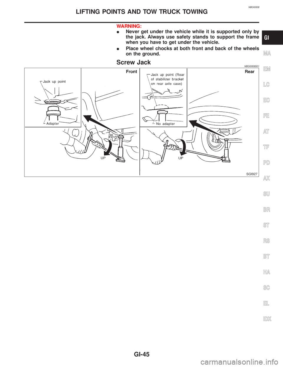
Screw JackNBGI0008S01
SGI927
MA
EM
LC
EC
FE
AT
TF
PD
AX
SU
BR
ST
RS
BT
HA
SC
EL
IDX
LIFTING POINTS AND TOW TRUCK TOWING
GI-45
Page 1792 of 2395

2-pole Lift=NBGI0008S03WARNING:
When lifting the vehicle, open the lift arms as wide as possible
and ensure that the front and rear of the vehicle are well bal-
anced.
When setting the lift arm, do not allow the arm to contact the
brake tubes, brake cable and fuel lines.
SGI133A
SGI988
Tow Truck TowingNBGI0008S04CAUTION:
IAll applicable state or Provincial (in Canada) laws and
local laws regarding the towing operation must be
obeyed.
IIt is necessary to use proper towing equipment to avoid
possible damage to the vehicle during towing operation.
Towing is in accordance with Towing Procedure Manual at
dealer.
IAlways attach safety chains before towing.
IWhen towing, make sure that the transmission, steering
system and power train are in good order. If any unit is
damaged, dollies must be used.
INever tow an automatic transmission model from the rear
(that is backward) with four wheels on the ground as this
may cause serious and expensive damage to the trans-
mission.
MA
EM
LC
EC
FE
AT
TF
PD
AX
SU
BR
ST
RS
BT
HA
SC
EL
IDX
LIFTING POINTS AND TOW TRUCK TOWING
2-pole Lift
GI-47
Page 1801 of 2395
Supplemental Restraint System (SRS) ªAIR
BAGº and ªSEAT BELT PRE-TENSIONERº
NBHA0001The Supplemental Restraint System such as ªAIR BAGº and ªSEAT BELT PRE-TENSIONERº used along with
a seat belt, helps to reduce the risk or severity of injury to the driver and front passenger for certain types of
collision. The SRS system composition which is available to INFINITI QX4 is as follows:
IFor a frontal collision
The Supplemental Restraint System consists of driver air bag module (located in the center of the steer-
ing wheel), front passenger air bag module (located on the instrument panel on passenger side), seat belt
pre-tensioners, a diagnosis sensor unit, warning lamp, wiring harness and spiral cable.
IFor a side collision
The Supplemental Restraint System consists of front side air bag module (located in the outer side of front
seat), satellite sensor, diagnosis sensor unit (one of components of air bags for a frontal collision), wiring
harness, warning lamp (one of components of air bags for a frontal collision).
Information necessary to service the system safely is included in theRS sectionof this Service Manual.
WARNING:
ITo avoid rendering the SRS inoperative, which could increase the risk of personal injury or death
in the event of a collision which would result in air bag inflation, all maintenance must be performed
by an authorized INFINITI dealer.
IImproper maintenance, including incorrect removal and installation of the SRS, can lead to per-
sonal injury caused by unintentional activation of the system. For removal of Spiral Cable and Air
Bag Module, see the RS section.
IDo not use electrical test equipment on any circuit related to the SRS unless instructed to in this
Service Manual. Spiral cable and wiring harnesses covered with yellow insulation tape either just
before the harness connectors or for the complete harness are related to the SRS.
Precautions for Working with HFC-134a
(R-134a)
NBHA0002WARNING:
ICFC-12 (R-12) refrigerant and HFC-134a (R-134a) refrigerant are not compatible. If the refrigerants
are mixed and compressor failure is likely to occur, refer to ªCONTAMINATED REFRIGERANTº
below. To determine the purity of HFC-134a (R-134a) in the vehicle and recovery tank, use Refrig-
erant Recovery/Recycling Recharging equipment (ACR4) (J-39500-INF) and Refrigerant Identifier.
IUse only specified lubricant for the HFC-134a (R-134a) A/C system and HFC-134a (R-134a) compo-
nents. If lubricant other than that specified is used, compressor failure is likely to occur.
IThe specified HFC-134a (R-134a) lubricant rapidly absorbs moisture from the atmosphere. The fol-
lowing handling precautions must be observed:
a) When removing refrigerant components from a vehicle, immediately cap (seal) the component to
minimize the entry of moisture from the atmosphere.
b) When installing refrigerant components to a vehicle, do not remove the caps (unseal) until just
before connecting the components. Connect all refrigerant loop components as quickly as pos-
sible to minimize the entry of moisture into system.
c) Only use the specified lubricant from a sealed container. Immediately reseal containers of lubri-
cant. Without proper sealing, lubricant will become moisture saturated and should not be used.
d) Avoid breathing A/C refrigerant and lubricant vapor or mist. Exposure may irritate eyes, nose and
throat. Remove R-134a from the A/C system, using certified service equipment meeting require-
ments of SAE J2210 (R-134a recycling equipment), or J2209 (R-134a recovery equipment). If acci-
dental system discharge occurs, ventilate work area before resuming service. Additional health and
safety information may be obtained from refrigerant and lubricant manufacturers.
e) Do not allow lubricant (Nissan A/C System Oil Type S) to come in contact with styrofoam parts.
Damage may result.
CONTAMINATED REFRIGERANTNBHA0002S01If a refrigerant other than pure R-134a is identified in a vehicle, your options are:
IExplain to the customer that environmental regulations prohibit the release of contaminated refrigerant into
the atmosphere.
IExplain that recovery of the contaminated refrigerant could damage your service equipment and refriger-
ant supply.
PRECAUTIONS
Supplemental Restraint System (SRS) ªAIR BAGº and ªSEAT BELT PRE-TENSIONERº
HA-2
Page 1802 of 2395
ISuggest the customer return the vehicle to the location of previous service where the contamination may
have occurred.
IIf you choose to perform the repair, recover the refrigerant using onlydedicated equipment and con-
tainers. Do not recover contaminated refrigerant into your existing service equipment.If your facil-
ity does not have dedicated recovery equipment, you may contact a local refrigerant product retailer for
available service. This refrigerant must be disposed of in accordance with all federal and local regulations.
In addition, replacement of all refrigerant system components on the vehicle is recommended.
IIf the vehicle is within the warranty period, the air conditioner warranty is void. Please contact Nissan
Customer Affairs for further assistance.
General Refrigerant PrecautionsNBHA0003WARNING:
IDo not release refrigerant into the air. Use approved recovery/recycling equipment to capture the
refrigerant every time an air conditioning system is discharged.
IAlways wear eye and hand protection (goggles and gloves) when working with any refrigerant or
air conditioning system.
IDo not store or heat refrigerant containers above 52ÉC (125ÉF).
IDo not heat a refrigerant container with an open flame; if container warming is required, place the
bottom of the container in a warm pail of water.
IDo not intentionally drop, puncture, or incinerate refrigerant containers.
IKeep refrigerant away from open flames: poisonous gas will be produced if refrigerant burns.
IRefrigerant will displace oxygen, therefore be certain to work in well ventilated areas to prevent
suffocation.
IDo not pressure test or leak test HFC-134a (R-134a) service equipment and/or vehicle air condi-
tioning systems with compressed air during repair. Some mixtures of air and R-134a have been
shown to be combustible at elevated pressures. These mixtures, if ignited, may cause injury or
property damage. Additional health and safety information may be obtained from refrigerant manu-
facturers.
Precautions for Leak Detection DyeNBHA0111IThe A/C system contains a fluorescent leak detection dye used for locating refrigerant leaks. An ultravio-
let (UV) lamp is required to illuminate the dye when inspecting for leaks.
IAlways wear fluorescence enhancing UV safety glasses to protect your eyes and enhance the visibility of
the fluorescent dye.
IThe fluorescent dye leak detector is not a replacement for an electronic refrigerant leak detector. The
fluorescent dye leak detector should be used in conjunction with an electronic refrigerant leak detector to
(J-41995) pin-point refrigerant leaks.
IFor your safety and your Customer's satisfaction, read and follow all manufacture's operating instructions
and precautions prior to performing the work.
IA compressor shaft seal should not be repaired because of dye seepage. The compressor shaft seal
should only be repaired after confirming the leak with an electronic refrigerant leak detector (J-41995).
IAlways remove and dye from the leak area after repairs are complete to avoid a misdiagnosis during a
future service.
IDo not allow dye to come into contact with painted body panels or interior components. If dye is spilled,
clean immediately with the approved dye cleaner. Fluorescent dye left on a surface for an extended period
of time cannot be removed.
IDo not spray the fluorescent dye cleaning agent on hot surfaces (engine exhaust manifold, etc.).
IDo not use more than one refrigerant dye bottle (1/4 ounce /7.4 cc) per A/C system.
ILeak detection dyes for R-134a and R12 A/C systems are different. Do not use R-134a leak detection dye
in R-12 A/C system or R-12 leak detector dye in R-134a A/C systems or A/C system damage may result.
IThe fluorescent properties of the dye will remain for over three (3) years unless a compressor failure
occurs.
GI
MA
EM
LC
EC
FE
AT
TF
PD
AX
SU
BR
ST
RS
BT
SC
EL
IDX
PRECAUTIONS
Precautions for Working with HFC-134a (R-134a) (Cont'd)
HA-3
Page 1804 of 2395
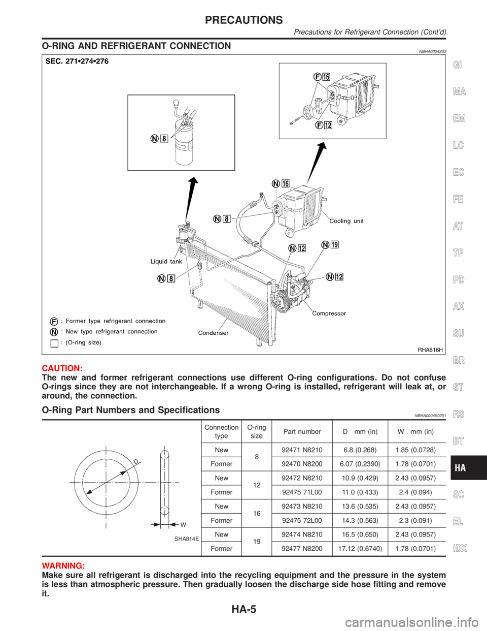
O-RING AND REFRIGERANT CONNECTIONNBHA0004S02
RHA816H
CAUTION:
The new and former refrigerant connections use different O-ring configurations. Do not confuse
O-rings since they are not interchangeable. If a wrong O-ring is installed, refrigerant will leak at, or
around, the connection.
O-Ring Part Numbers and SpecificationsNBHA0004S0201
SHA814E
Connection
typeO-ring
sizePart number D mm (in) W mm (in)
New
892471 N8210 6.8 (0.268) 1.85 (0.0728)
Former 92470 N8200 6.07 (0.2390) 1.78 (0.0701)
New
1292472 N8210 10.9 (0.429) 2.43 (0.0957)
Former 92475 71L00 11.0 (0.433) 2.4 (0.094)
New
1692473 N8210 13.6 (0.535) 2.43 (0.0957)
Former 92475 72L00 14.3 (0.563) 2.3 (0.091)
New
1992474 N8210 16.5 (0.650) 2.43 (0.0957)
Former 92477 N8200 17.12 (0.6740) 1.78 (0.0701)
WARNING:
Make sure all refrigerant is discharged into the recycling equipment and the pressure in the system
is less than atmospheric pressure. Then gradually loosen the discharge side hose fitting and remove
it.
GI
MA
EM
LC
EC
FE
AT
TF
PD
AX
SU
BR
ST
RS
BT
SC
EL
IDX
PRECAUTIONS
Precautions for Refrigerant Connection (Cont'd)
HA-5
Page 1943 of 2395
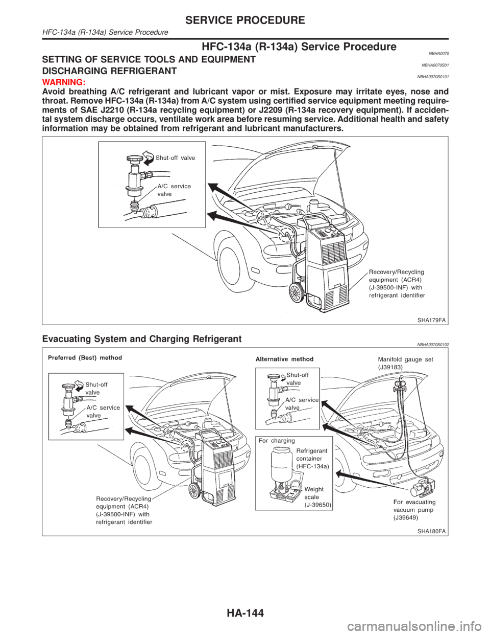
HFC-134a (R-134a) Service ProcedureNBHA0070SETTING OF SERVICE TOOLS AND EQUIPMENTNBHA0070S01DISCHARGING REFRIGERANTNBHA0070S0101WARNING:
Avoid breathing A/C refrigerant and lubricant vapor or mist. Exposure may irritate eyes, nose and
throat. Remove HFC-134a (R-134a) from A/C system using certified service equipment meeting require-
ments of SAE J2210 (R-134a recycling equipment) or J2209 (R-134a recovery equipment). If acciden-
tal system discharge occurs, ventilate work area before resuming service. Additional health and safety
information may be obtained from refrigerant and lubricant manufacturers.
SHA179FA
Evacuating System and Charging RefrigerantNBHA0070S0102
SHA180FA
SERVICE PROCEDURE
HFC-134a (R-134a) Service Procedure
HA-144