Page 2343 of 2395
Symptom 8. Tight Corner Braking SymptomNBTF0036SYMPTOM: Tight corner braking symptom occurs. (Hydraulic
system failure)
1 CHECK INPUT SIGNAL
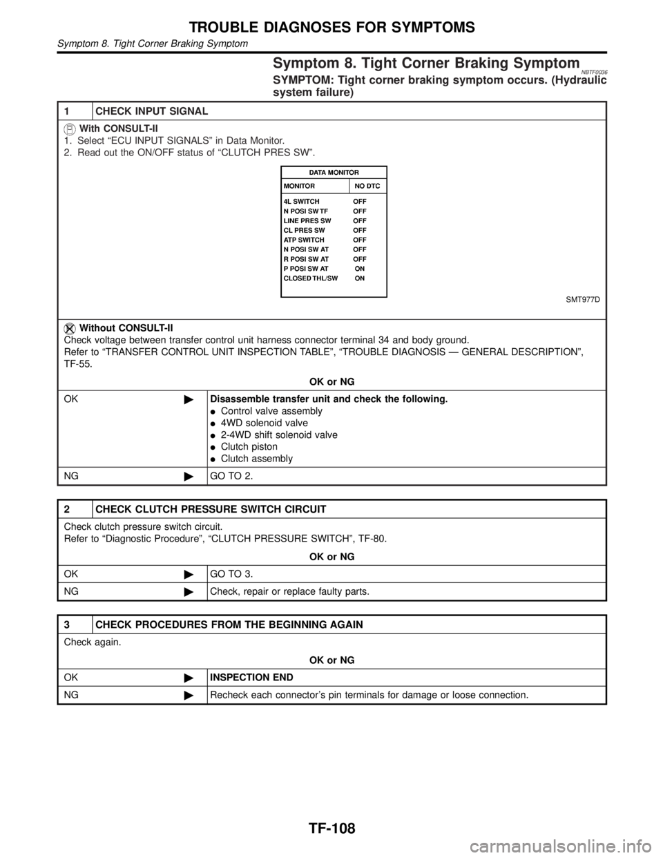
With CONSULT-II
1. Select ªECU INPUT SIGNALSº in Data Monitor.
2. Read out the ON/OFF status of ªCLUTCH PRES SWº.
SMT977D
Without CONSULT-II
Check voltage between transfer control unit harness connector terminal 34 and body ground.
Refer to ªTRANSFER CONTROL UNIT INSPECTION TABLEº, ªTROUBLE DIAGNOSIS Ð GENERAL DESCRIPTIONº,
TF-55.
OK or NG
OK©Disassemble transfer unit and check the following.
IControl valve assembly
I4WD solenoid valve
I2-4WD shift solenoid valve
IClutch piston
IClutch assembly
NG©GO TO 2.
2 CHECK CLUTCH PRESSURE SWITCH CIRCUIT
Check clutch pressure switch circuit.
Refer to ªDiagnostic Procedureº, ªCLUTCH PRESSURE SWITCHº, TF-80.
OK or NG
OK©GO TO 3.
NG©Check, repair or replace faulty parts.
3 CHECK PROCEDURES FROM THE BEGINNING AGAIN
Check again.
OK or NG
OK©INSPECTION END
NG©Recheck each connector's pin terminals for damage or loose connection.
TROUBLE DIAGNOSES FOR SYMPTOMS
Symptom 8. Tight Corner Braking Symptom
TF-108
Page 2344 of 2395
Symptom 9. 4WD System Does Not Operate=NBTF0037SYMPTOM: The vehicle cannot be put into 4WD mode.
(Hydraulic system failure)
1 CHECK INPUT SIGNAL
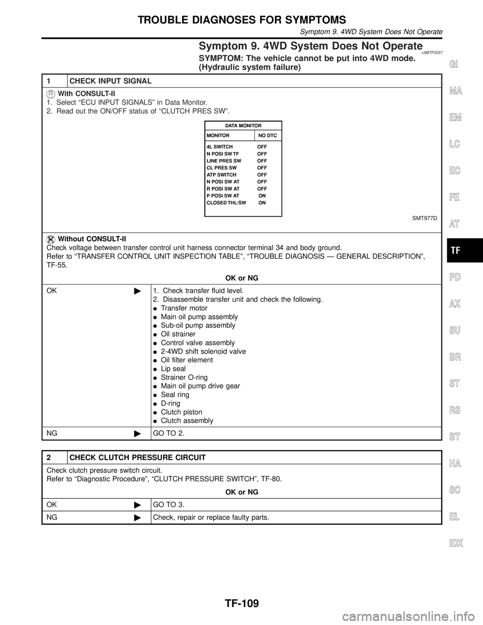
With CONSULT-II
1. Select ªECU INPUT SIGNALSº in Data Monitor.
2. Read out the ON/OFF status of ªCLUTCH PRES SWº.
SMT977D
Without CONSULT-II
Check voltage between transfer control unit harness connector terminal 34 and body ground.
Refer to ªTRANSFER CONTROL UNIT INSPECTION TABLEº, ªTROUBLE DIAGNOSIS Ð GENERAL DESCRIPTIONº,
TF-55.
OK or NG
OK©1. Check transfer fluid level.
2. Disassemble transfer unit and check the following.
ITransfer motor
IMain oil pump assembly
ISub-oil pump assembly
IOil strainer
IControl valve assembly
I2-4WD shift solenoid valve
IOil filter element
ILip seal
IStrainer O-ring
IMain oil pump drive gear
ISeal ring
ID-ring
IClutch piston
IClutch assembly
NG©GO TO 2.
2 CHECK CLUTCH PRESSURE CIRCUIT
Check clutch pressure switch circuit.
Refer to ªDiagnostic Procedureº, ªCLUTCH PRESSURE SWITCHº, TF-80.
OK or NG
OK©GO TO 3.
NG©Check, repair or replace faulty parts.
GI
MA
EM
LC
EC
FE
AT
PD
AX
SU
BR
ST
RS
BT
HA
SC
EL
IDX
TROUBLE DIAGNOSES FOR SYMPTOMS
Symptom 9. 4WD System Does Not Operate
TF-109
Page 2345 of 2395
3 CHECK PROCEDURES FROM THE BEGINNING
Check again.
OK or NG
OK©INSPECTION END
NG©Recheck each connector's pin terminals for damage or loose connection.
TROUBLE DIAGNOSES FOR SYMPTOMS
Symptom 9. 4WD System Does Not Operate (Cont'd)
TF-110
Page 2346 of 2395

NBTF0038
SMT858D
4WD Shift SwitchNBTF0038S01Check continuity between each terminal.
Terminals Switch position Continuity
1-22WD Yes
Except 2WD No
1-3,1-4AUTO Yes
Except AUTO No
1-4,1-54H Yes
Except 4H No
1-4,1-64LO Yes
Except 4LO No
SMT079D
2-4WD Shift Solenoid Valve and Transfer Fluid
Temperature Sensor
NBTF0038S02Measure resistance between terminals of transfer terminal cord
assembly sub-harness connector located on rear-right of transfer
unit.
Component parts Terminals Resistance
2-4WD shift solenoid valve 4 - 5Approx. 20ÉC (68ÉF):
Approx. 22.8 - 25.2W
Transfer fluid temperature
sensor2-3Approx. 20ÉC (68ÉF): Approx. 2.5 kW
Approx. 80ÉC (176ÉF): Approx. 0.3
kW
SMT080D
4WD Solenoid Valve, Clutch Pressure Switch
and Line Pressure Switch
NBTF0038S03Measure resistance between terminals of transfer terminal cord
assembly sub-harness connector located on rear-right of transfer
unit.
GI
MA
EM
LC
EC
FE
AT
PD
AX
SU
BR
ST
RS
BT
HA
SC
EL
IDX
COMPONENT INSPECTION
4WD Shift Switch
TF-111
Page 2347 of 2395
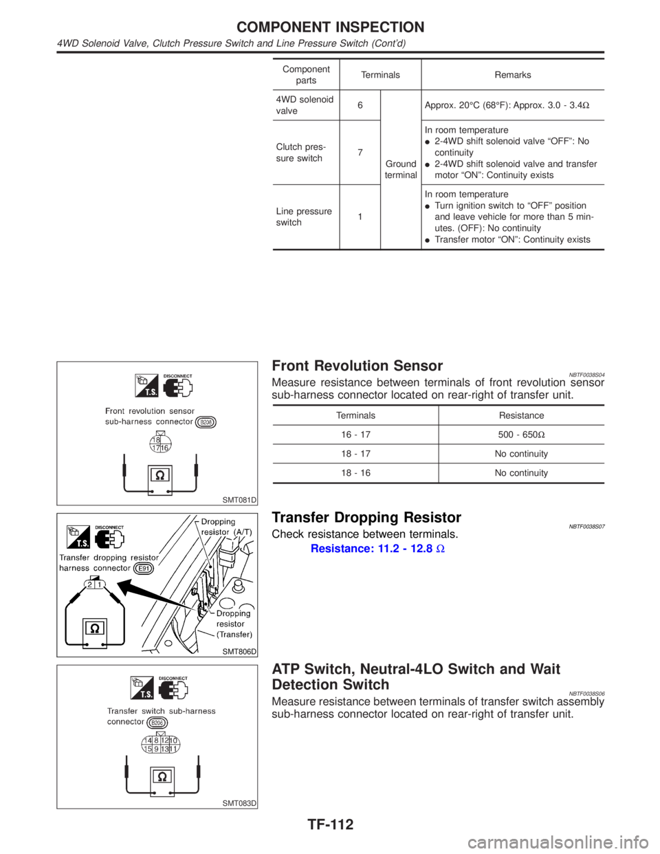
Component
partsTerminals Remarks
4WD solenoid
valve6
Ground
terminalApprox. 20ÉC (68ÉF): Approx. 3.0 - 3.4W
Clutch pres-
sure switch7In room temperature
I2-4WD shift solenoid valve ªOFFº: No
continuity
I2-4WD shift solenoid valve and transfer
motor ªONº: Continuity exists
Line pressure
switch1In room temperature
ITurn ignition switch to ªOFFº position
and leave vehicle for more than 5 min-
utes. (OFF): No continuity
ITransfer motor ªONº: Continuity exists
SMT081D
Front Revolution SensorNBTF0038S04Measure resistance between terminals of front revolution sensor
sub-harness connector located on rear-right of transfer unit.
Terminals Resistance
16 - 17 500 - 650W
18 - 17 No continuity
18 - 16 No continuity
SMT806D
Transfer Dropping ResistorNBTF0038S07Check resistance between terminals.
Resistance: 11.2 - 12.8W
SMT083D
ATP Switch, Neutral-4LO Switch and Wait
Detection Switch
NBTF0038S06Measure resistance between terminals of transfer switch assembly
sub-harness connector located on rear-right of transfer unit.
COMPONENT INSPECTION
4WD Solenoid Valve, Clutch Pressure Switch and Line Pressure Switch (Cont'd)
TF-112
Page 2348 of 2395
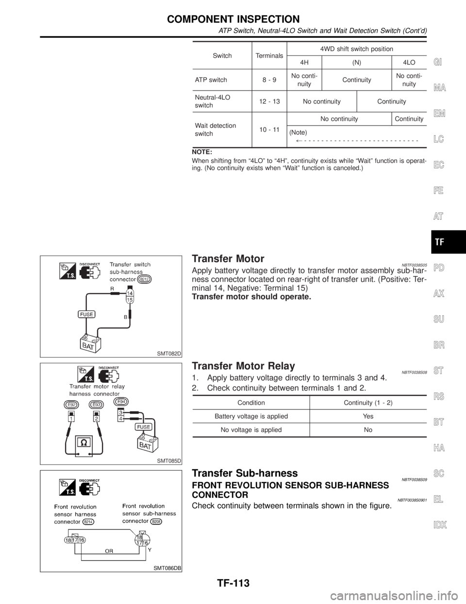
Switch Terminals4WD shift switch position
4H (N) 4LO
ATP switch 8 - 9No conti-
nuityContinuityNo conti-
nuity
Neutral-4LO
switch12 - 13 No continuity Continuity
Wait detection
switch10-11No continuity Continuity
(Note)
+---------------------------
NOTE:
When shifting from ª4LOº to ª4Hº, continuity exists while ªWaitº function is operat-
ing. (No continuity exists when ªWaitº function is canceled.)
SMT082D
Transfer MotorNBTF0038S05Apply battery voltage directly to transfer motor assembly sub-har-
ness connector located on rear-right of transfer unit. (Positive: Ter-
minal 14, Negative: Terminal 15)
Transfer motor should operate.
SMT085D
Transfer Motor RelayNBTF0038S081. Apply battery voltage directly to terminals 3 and 4.
2. Check continuity between terminals 1 and 2.
Condition Continuity (1 - 2)
Battery voltage is applied Yes
No voltage is applied No
SMT086DB
Transfer Sub-harnessNBTF0038S09FRONT REVOLUTION SENSOR SUB-HARNESS
CONNECTOR
NBTF0038S0901Check continuity between terminals shown in the figure.
GI
MA
EM
LC
EC
FE
AT
PD
AX
SU
BR
ST
RS
BT
HA
SC
EL
IDX
COMPONENT INSPECTION
ATP Switch, Neutral-4LO Switch and Wait Detection Switch (Cont'd)
TF-113
Page 2349 of 2395
SMT087D
TRANSFER SWITCH ASSEMBLY SUB-HARNESS
CONNECTOR
NBTF0038S0902Check continuity between terminals shown in the figure.
SMT088D
TRANSFER TERMINAL CORD ASSEMBLY
SUB-HARNESS CONNECTOR
NBTF0038S0903Check continuity between terminals shown in the figure.
Terminals on solenoid valve
Terminals Components
6 4WD solenoid valve
4, 5 2-4WD shift solenoid valve
2, 3 Transfer fluid temperature sensor
7 Clutch pressure switch
1 Line pressure switch
SMT807D
Transfer Shift Relay (High & low)NBTF0038S10Check continuity between terminals 3 and 4.
Condition Continuity
12V direct current supply
between terminals 1 and 2No
No current supply Yes
COMPONENT INSPECTION
Transfer Sub-harness (Cont'd)
TF-114
Page 2354 of 2395
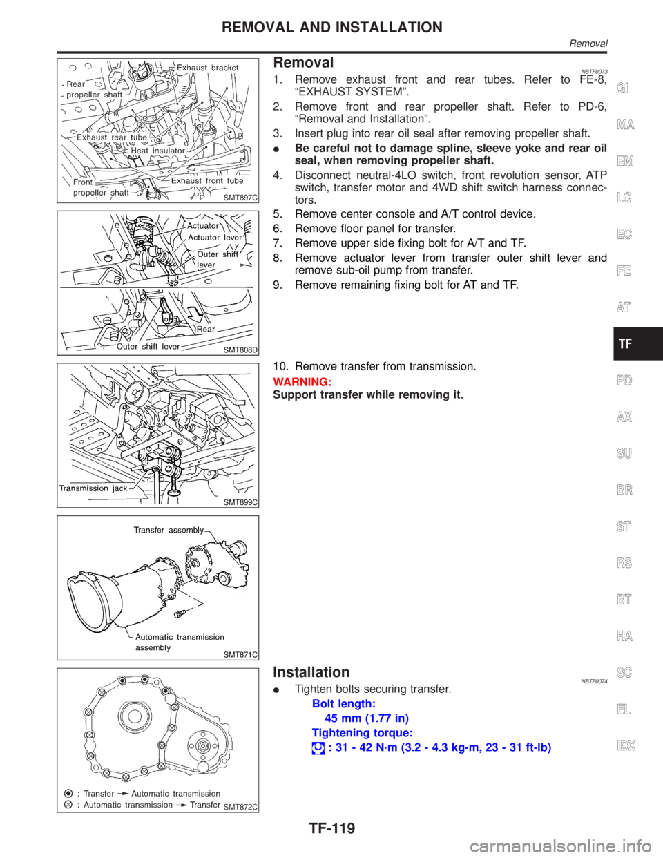
SMT897C
RemovalNBTF00731. Remove exhaust front and rear tubes. Refer to FE-8,
ªEXHAUST SYSTEMº.
2. Remove front and rear propeller shaft. Refer to PD-6,
ªRemoval and Installationº.
3. Insert plug into rear oil seal after removing propeller shaft.
IBe careful not to damage spline, sleeve yoke and rear oil
seal, when removing propeller shaft.
4. Disconnect neutral-4LO switch, front revolution sensor, ATP
switch, transfer motor and 4WD shift switch harness connec-
tors.
SMT808D
5. Remove center console and A/T control device.
6. Remove floor panel for transfer.
7. Remove upper side fixing bolt for A/T and TF.
8. Remove actuator lever from transfer outer shift lever and
remove sub-oil pump from transfer.
9. Remove remaining fixing bolt for AT and TF.
SMT899C
SMT871C
10. Remove transfer from transmission.
WARNING:
Support transfer while removing it.
SMT872C
InstallationNBTF0074ITighten bolts securing transfer.
Bolt length:
45 mm (1.77 in)
Tightening torque:
: 31 - 42 N´m (3.2 - 4.3 kg-m, 23 - 31 ft-lb)
GI
MA
EM
LC
EC
FE
AT
PD
AX
SU
BR
ST
RS
BT
HA
SC
EL
IDX
REMOVAL AND INSTALLATION
Removal
TF-119