2001 INFINITI QX4 check oil
[x] Cancel search: check oilPage 1644 of 2395
ENGINE MECHANICAL
SECTION
EM
CONTENTS
PRECAUTIONS...............................................................3
Parts Requiring Angular Tightening .............................3
Liquid Gasket Application Procedure ..........................3
PREPARATION...............................................................4
Special Service Tools ..................................................4
Commercial Service Tools ...........................................6
NOISE, VIBRATION AND HARSHNESS (NVH)
TROUBLESHOOTING.....................................................8
NVH Troubleshooting - Engine Noise .........................9
OUTER COMPONENT PARTS.....................................10
Removal and Installation ...........................................10
TIGHTENING PROCEDURES...................................12
MEASUREMENT OF COMPRESSION PRESSURE....14
OIL PAN.........................................................................15
Components...............................................................15
Removal .....................................................................15
Installation ..................................................................18
TIMING CHAIN..............................................................20
Components...............................................................20
POSITION FOR APPLYING LIQUID GASKET............21
Removal .....................................................................23
Inspection...................................................................29
Installation ..................................................................29
OIL SEAL.......................................................................35
Replacement ..............................................................35
VALVE OIL SEAL.....................................................35
OIL SEAL INSTALLATION DIRECTION.....................36
FRONT OIL SEAL....................................................36
REAR OIL SEAL......................................................36
CYLINDER HEAD..........................................................38
Components...............................................................38
Removal .....................................................................39
Disassembly...............................................................41
Inspection...................................................................42
CYLINDER HEAD DISTORTION...............................42
CAMSHAFT VISUAL CHECK....................................42
CAMSHAFT RUNOUT..............................................42
CAMSHAFT CAM HEIGHT.......................................42
CAMSHAFT JOURNAL CLEARANCE........................42
CAMSHAFT END PLAY............................................43
CAMSHAFT SPROCKET RUNOUT...........................43
VALVE GUIDE CLEARANCE....................................43
VALVE GUIDE REPLACEMENT................................44
VALVE SEATS.........................................................45
REPLACING VALVE SEAT FOR SERVICE PARTS....45
VALVE DIMENSIONS...............................................46
VALVE SPRING.......................................................46
VALVE LIFTER........................................................46
Assembly ...................................................................47
Installation ..................................................................47
Valve Clearance.........................................................52
CHECKING.............................................................52
ADJUSTING............................................................54
ENGINE ASSEMBLY.....................................................57
Removal and Installation ...........................................57
REMOVAL...............................................................58
INSTALLATION........................................................60
CYLINDER BLOCK.......................................................61
Components...............................................................61
CYLINDER BLOCK HEATER....................................62
Removal and Installation ...........................................62
Disassembly...............................................................62
PISTON, CRANKSHAFT AND OIL JET......................62
Inspection...................................................................63
PISTON AND PISTON PIN CLEARANCE..................63
PISTON RING SIDE CLEARANCE............................64
PISTON RING END GAP..........................................64
CONNECTING ROD BEND AND TORSION...............65
CYLINDER BLOCK DISTORTION AND WEAR...........65
PISTON-TO-BORE CLEARANCE..............................66
CRANKSHAFT.........................................................67
BEARING CLEARANCE...........................................67
CONNECTING ROD BUSHING CLEARANCE
(SMALL END)
..........................................................70
DRIVE PLATE RUNOUT..........................................70
Assembly ...................................................................71
PISTON..................................................................71
OIL JET..................................................................71
CRANKSHAFT.........................................................71
REPLACEMENT OF PILOT CONVERTER.................74
DRIVE PLATE.........................................................74
GI
MA
LC
EC
FE
AT
TF
PD
AX
SU
BR
ST
RS
BT
HA
SC
EL
IDX
Page 1652 of 2395
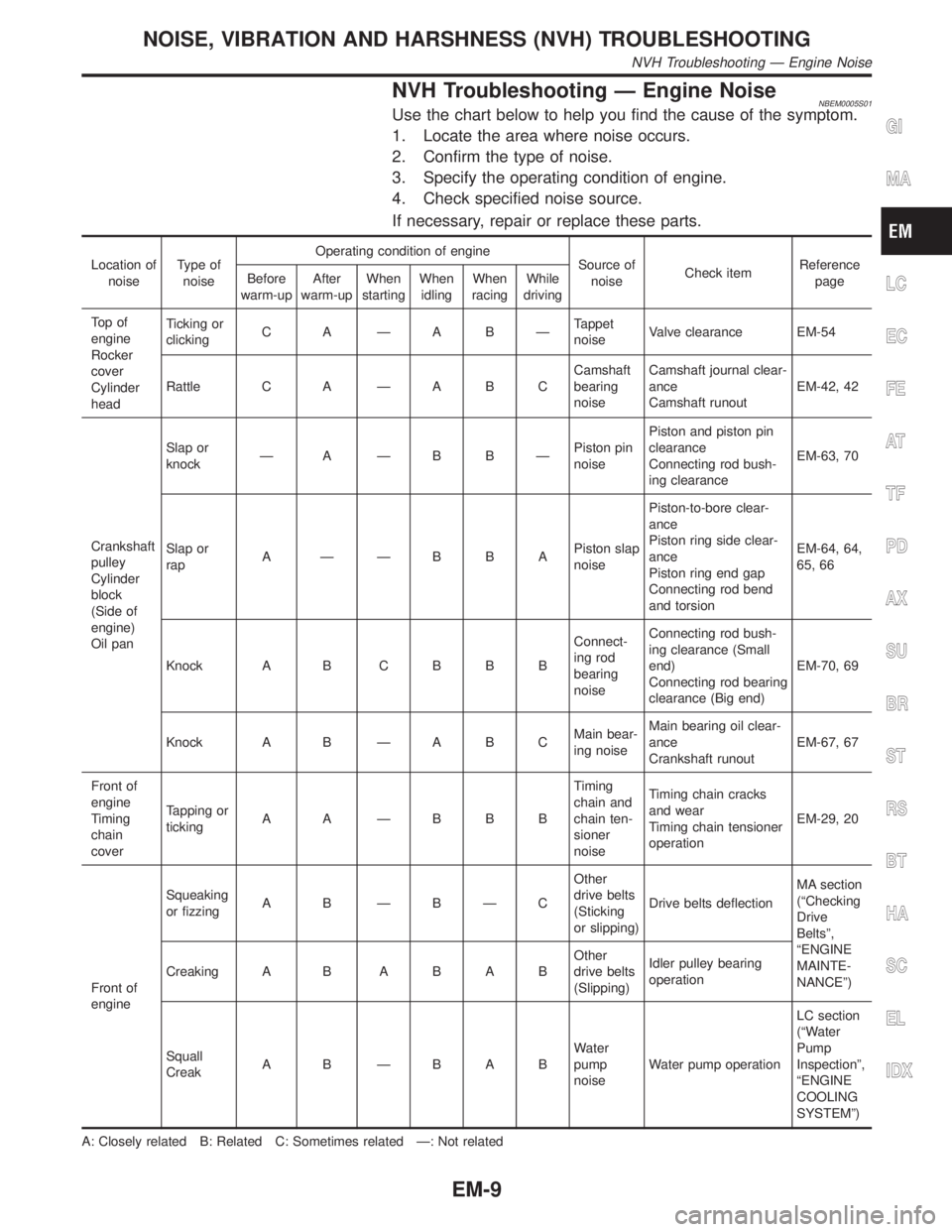
NVH Troubleshooting Ð Engine NoiseNBEM0005S01Use the chart below to help you find the cause of the symptom.
1. Locate the area where noise occurs.
2. Confirm the type of noise.
3. Specify the operating condition of engine.
4. Check specified noise source.
If necessary, repair or replace these parts.
Location of
noiseType of
noiseOperating condition of engine
Source of
noiseCheck itemReference
page Before
warm-upAfter
warm-upWhen
startingWhen
idlingWhen
racingWhile
driving
To p o f
engine
Rocker
cover
Cylinder
headTicking or
clickingC A ÐA BÐTappet
noiseValve clearance EM-54
Rattle C A Ð A B CCamshaft
bearing
noiseCamshaft journal clear-
ance
Camshaft runoutEM-42, 42
Crankshaft
pulley
Cylinder
block
(Side of
engine)
Oil panSlap or
knockÐ A ÐB BÐPiston pin
noisePiston and piston pin
clearance
Connecting rod bush-
ing clearanceEM-63, 70
Slap or
rapA ÐÐBBAPiston slap
noisePiston-to-bore clear-
ance
Piston ring side clear-
ance
Piston ring end gap
Connecting rod bend
and torsionEM-64, 64,
65, 66
Knock A B C B B BConnect-
ing rod
bearing
noiseConnecting rod bush-
ing clearance (Small
end)
Connecting rod bearing
clearance (Big end)EM-70, 69
Knock A B Ð A B CMain bear-
ing noiseMain bearing oil clear-
ance
Crankshaft runoutEM-67, 67
Front of
engine
Timing
chain
coverTapping or
tickingA A ÐBBBTiming
chain and
chain ten-
sioner
noiseTiming chain cracks
and wear
Timing chain tensioner
operationEM-29, 20
Front of
engineSqueaking
or fizzingA B ÐBÐCOther
drive belts
(Sticking
or slipping)Drive belts deflectionMA section
(ªChecking
Drive
Beltsº,
ªENGINE
MAINTE-
NANCEº) Creaking A BABABOther
drive belts
(Slipping)Idler pulley bearing
operation
Squall
CreakA B ÐBABWater
pump
noiseWater pump operationLC section
(ªWater
Pump
Inspectionº,
ªENGINE
COOLING
SYSTEMº)
A: Closely related B: Related C: Sometimes related Ð: Not related
GI
MA
LC
EC
FE
AT
TF
PD
AX
SU
BR
ST
RS
BT
HA
SC
EL
IDX
NOISE, VIBRATION AND HARSHNESS (NVH) TROUBLESHOOTING
NVH Troubleshooting Ð Engine Noise
EM-9
Page 1657 of 2395
NBEM0007
SEM480G
SEM481G
JEM482G
SEM387C
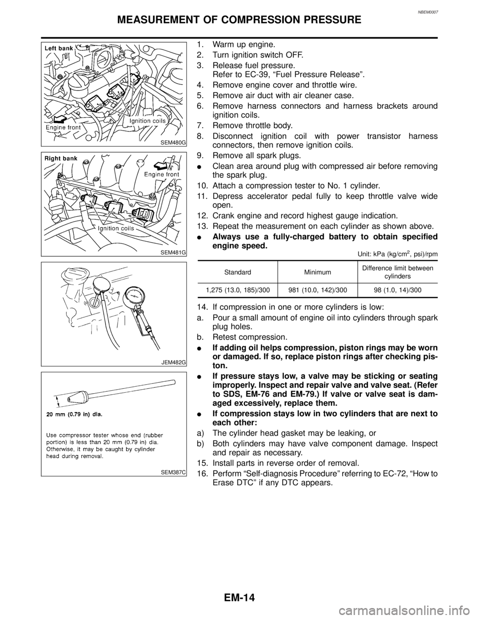
1. Warm up engine.
2. Turn ignition switch OFF.
3. Release fuel pressure.
Refer to EC-39, ªFuel Pressure Releaseº.
4. Remove engine cover and throttle wire.
5. Remove air duct with air cleaner case.
6. Remove harness connectors and harness brackets around
ignition coils.
7. Remove throttle body.
8. Disconnect ignition coil with power transistor harness
connectors, then remove ignition coils.
9. Remove all spark plugs.
IClean area around plug with compressed air before removing
the spark plug.
10. Attach a compression tester to No. 1 cylinder.
11. Depress accelerator pedal fully to keep throttle valve wide
open.
12. Crank engine and record highest gauge indication.
13. Repeat the measurement on each cylinder as shown above.
IAlways use a fully-charged battery to obtain specified
engine speed.
Unit: kPa (kg/cm2, psi)/rpm
Standard MinimumDifference limit between
cylinders
1,275 (13.0, 185)/300 981 (10.0, 142)/300 98 (1.0, 14)/300
14. If compression in one or more cylinders is low:
a. Pour a small amount of engine oil into cylinders through spark
plug holes.
b. Retest compression.
IIf adding oil helps compression, piston rings may be worn
or damaged. If so, replace piston rings after checking pis-
ton.
IIf pressure stays low, a valve may be sticking or seating
improperly. Inspect and repair valve and valve seat. (Refer
to SDS, EM-76 and EM-79.) If valve or valve seat is dam-
aged excessively, replace them.
IIf compression stays low in two cylinders that are next to
each other:
a) The cylinder head gasket may be leaking, or
b) Both cylinders may have valve component damage. Inspect
and repair as necessary.
15. Install parts in reverse order of removal.
16. Perform ªSelf-diagnosis Procedureº referring to EC-72, ªHow to
Erase DTCº if any DTC appears.
MEASUREMENT OF COMPRESSION PRESSURE
EM-14
Page 1668 of 2395
SEM415G
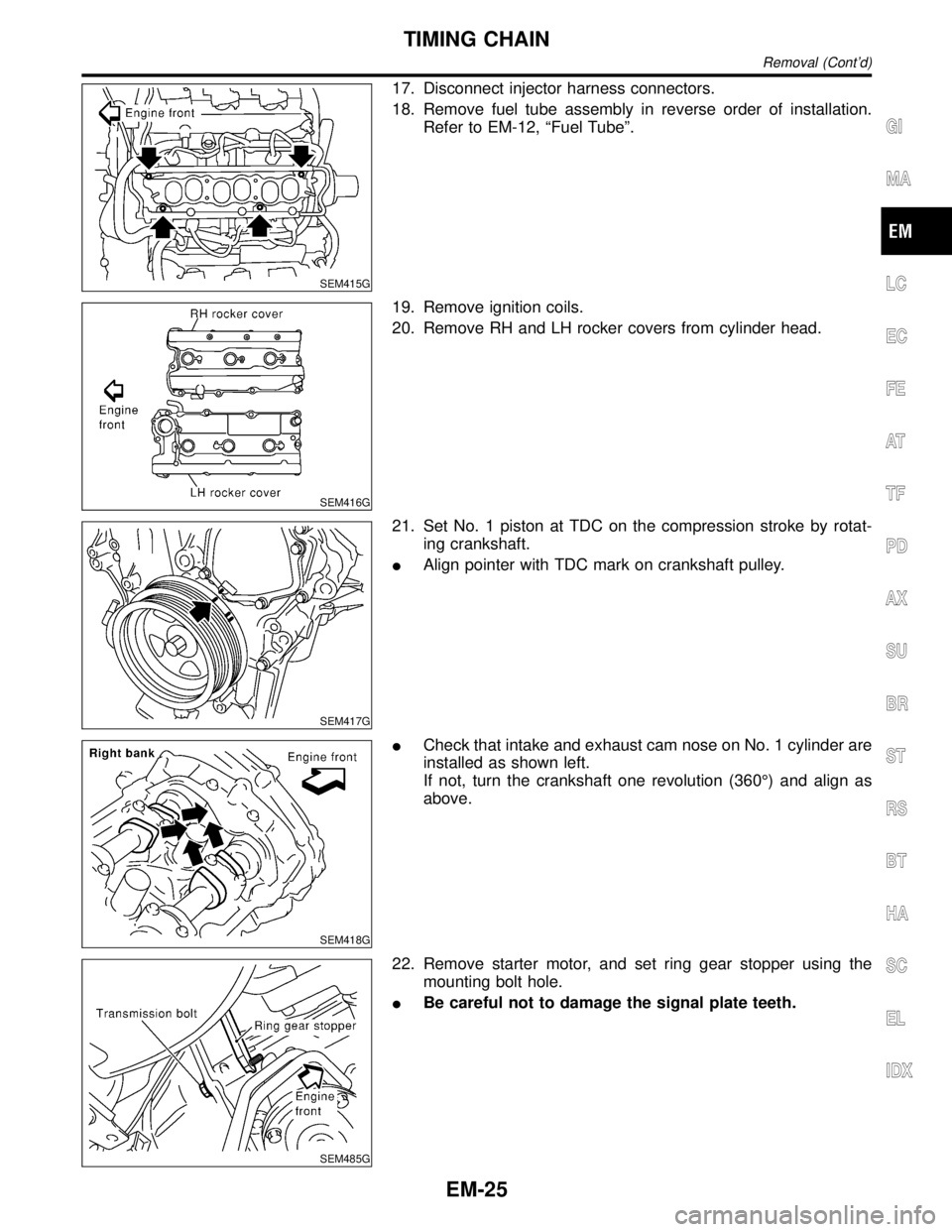
17. Disconnect injector harness connectors.
18. Remove fuel tube assembly in reverse order of installation.
Refer to EM-12, ªFuel Tubeº.
SEM416G
19. Remove ignition coils.
20. Remove RH and LH rocker covers from cylinder head.
SEM417G
21. Set No. 1 piston at TDC on the compression stroke by rotat-
ing crankshaft.
IAlign pointer with TDC mark on crankshaft pulley.
SEM418G
ICheck that intake and exhaust cam nose on No. 1 cylinder are
installed as shown left.
If not, turn the crankshaft one revolution (360É) and align as
above.
SEM485G
22. Remove starter motor, and set ring gear stopper using the
mounting bolt hole.
IBe careful not to damage the signal plate teeth.
GI
MA
LC
EC
FE
AT
TF
PD
AX
SU
BR
ST
RS
BT
HA
SC
EL
IDX
TIMING CHAIN
Removal (Cont'd)
EM-25
Page 1672 of 2395
SEM928E
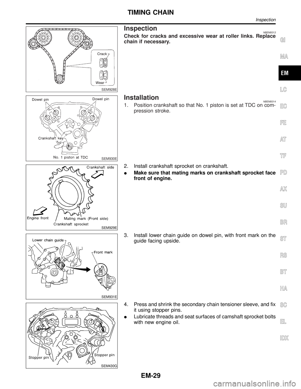
InspectionNBEM0013Check for cracks and excessive wear at roller links. Replace
chain if necessary.
SEM930E
InstallationNBEM00141. Position crankshaft so that No. 1 piston is set at TDC on com-
pression stroke.
SEM929E
2. Install crankshaft sprocket on crankshaft.
IMake sure that mating marks on crankshaft sprocket face
front of engine.
SEM931E
3. Install lower chain guide on dowel pin, with front mark on the
guide facing upside.
SEM430G
4. Press and shrink the secondary chain tensioner sleeve, and fix
it using stopper pins.
ILubricate threads and seat surfaces of camshaft sprocket bolts
with new engine oil.
GI
MA
LC
EC
FE
AT
TF
PD
AX
SU
BR
ST
RS
BT
HA
SC
EL
IDX
TIMING CHAIN
Inspection
EM-29
Page 1684 of 2395
SEM444G
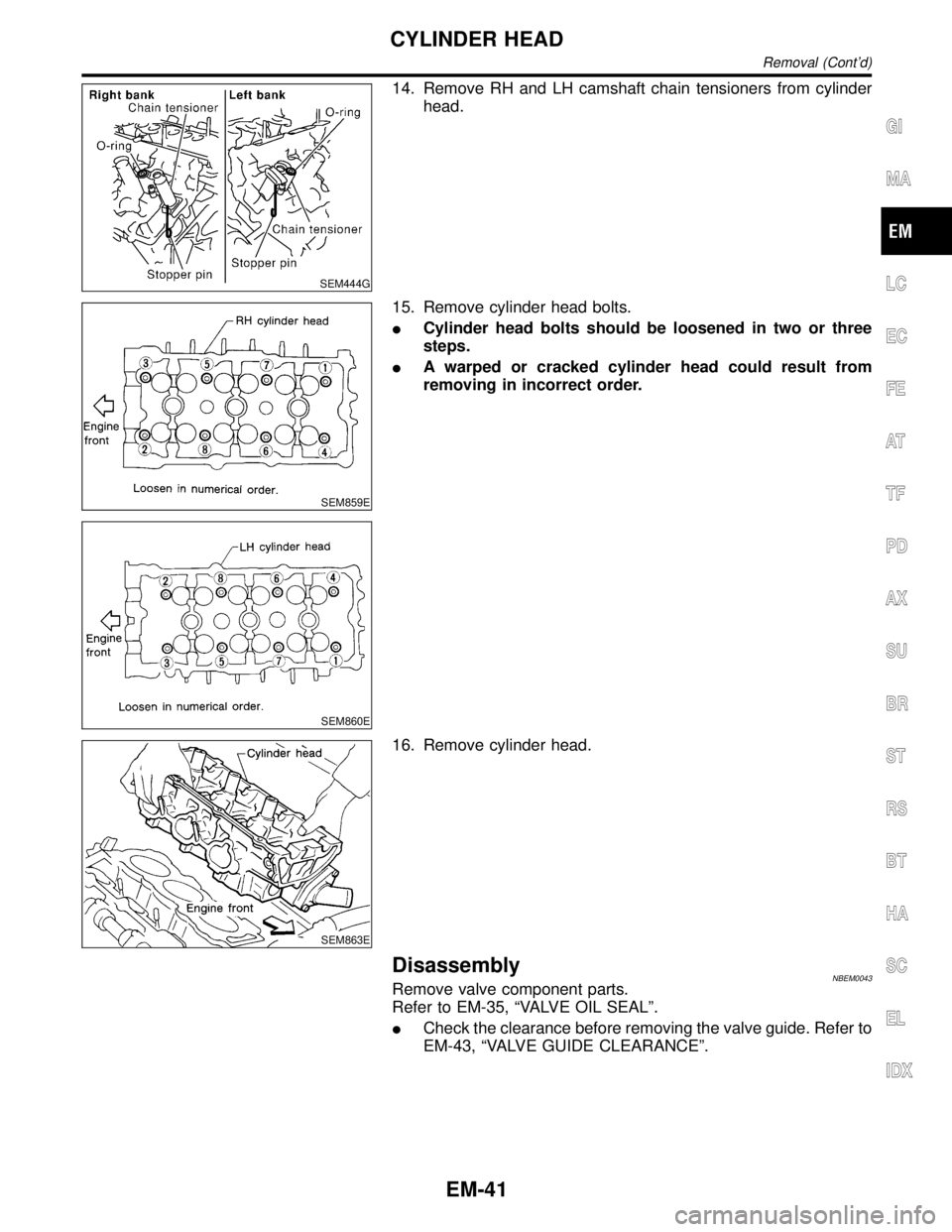
14. Remove RH and LH camshaft chain tensioners from cylinder
head.
SEM859E
SEM860E
15. Remove cylinder head bolts.
ICylinder head bolts should be loosened in two or three
steps.
IA warped or cracked cylinder head could result from
removing in incorrect order.
SEM863E
16. Remove cylinder head.
DisassemblyNBEM0043Remove valve component parts.
Refer to EM-35, ªVALVE OIL SEALº.
ICheck the clearance before removing the valve guide. Refer to
EM-43, ªVALVE GUIDE CLEARANCEº.
GI
MA
LC
EC
FE
AT
TF
PD
AX
SU
BR
ST
RS
BT
HA
SC
EL
IDX
CYLINDER HEAD
Removal (Cont'd)
EM-41
Page 1687 of 2395
SEM938C
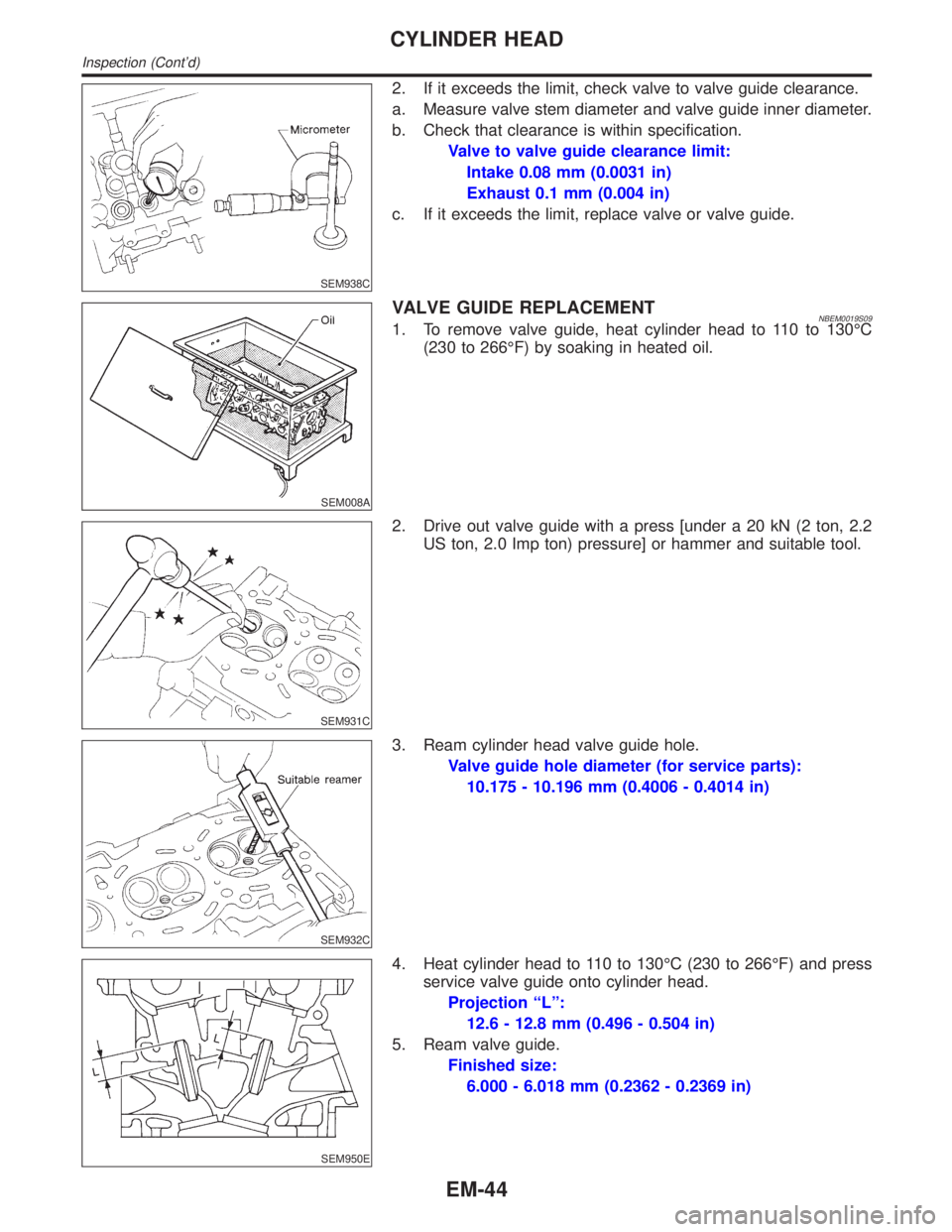
2. If it exceeds the limit, check valve to valve guide clearance.
a. Measure valve stem diameter and valve guide inner diameter.
b. Check that clearance is within specification.
Valve to valve guide clearance limit:
Intake 0.08 mm (0.0031 in)
Exhaust 0.1 mm (0.004 in)
c. If it exceeds the limit, replace valve or valve guide.
SEM008A
VALVE GUIDE REPLACEMENTNBEM0019S091. To remove valve guide, heat cylinder head to 110 to 130ÉC
(230 to 266ÉF) by soaking in heated oil.
SEM931C
2. Drive out valve guide with a press [under a 20 kN (2 ton, 2.2
US ton, 2.0 Imp ton) pressure] or hammer and suitable tool.
SEM932C
3. Ream cylinder head valve guide hole.
Valve guide hole diameter (for service parts):
10.175 - 10.196 mm (0.4006 - 0.4014 in)
SEM950E
4. Heat cylinder head to 110 to 130ÉC (230 to 266ÉF) and press
service valve guide onto cylinder head.
Projection ªLº:
12.6 - 12.8 mm (0.496 - 0.504 in)
5. Ream valve guide.
Finished size:
6.000 - 6.018 mm (0.2362 - 0.2369 in)
CYLINDER HEAD
Inspection (Cont'd)
EM-44
Page 1688 of 2395
SEM934C
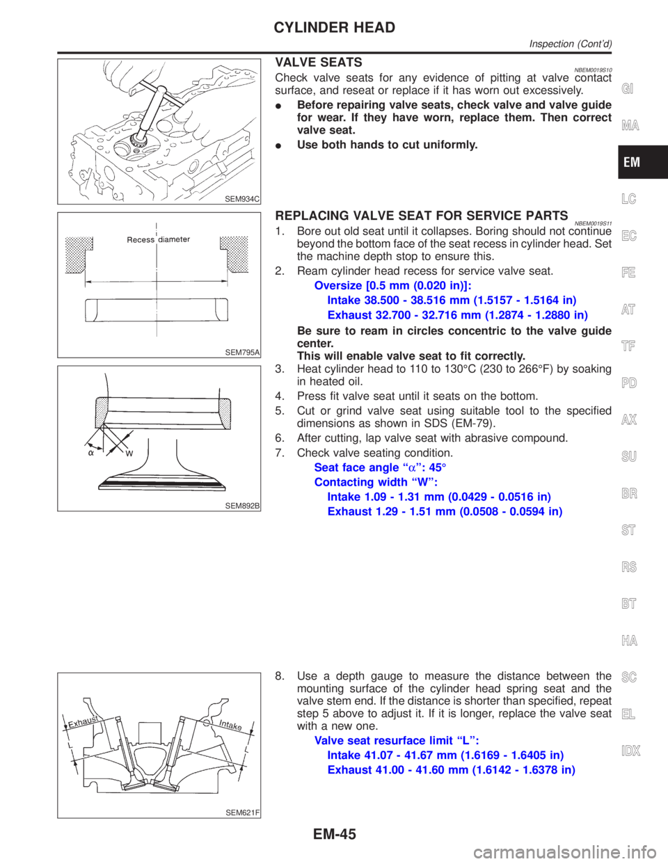
VALVE SEATSNBEM0019S10Check valve seats for any evidence of pitting at valve contact
surface, and reseat or replace if it has worn out excessively.
IBefore repairing valve seats, check valve and valve guide
for wear. If they have worn, replace them. Then correct
valve seat.
IUse both hands to cut uniformly.
SEM795A
REPLACING VALVE SEAT FOR SERVICE PARTSNBEM0019S111. Bore out old seat until it collapses. Boring should not continue
beyond the bottom face of the seat recess in cylinder head. Set
the machine depth stop to ensure this.
2. Ream cylinder head recess for service valve seat.
Oversize [0.5 mm (0.020 in)]:
Intake 38.500 - 38.516 mm (1.5157 - 1.5164 in)
Exhaust 32.700 - 32.716 mm (1.2874 - 1.2880 in)
Be sure to ream in circles concentric to the valve guide
center.
This will enable valve seat to fit correctly.
SEM892B
3. Heat cylinder head to 110 to 130ÉC (230 to 266ÉF) by soaking
in heated oil.
4. Press fit valve seat until it seats on the bottom.
5. Cut or grind valve seat using suitable tool to the specified
dimensions as shown in SDS (EM-79).
6. After cutting, lap valve seat with abrasive compound.
7. Check valve seating condition.
Seat face angle ªaº: 45É
Contacting width ªWº:
Intake 1.09 - 1.31 mm (0.0429 - 0.0516 in)
Exhaust 1.29 - 1.51 mm (0.0508 - 0.0594 in)
SEM621F
8. Use a depth gauge to measure the distance between the
mounting surface of the cylinder head spring seat and the
valve stem end. If the distance is shorter than specified, repeat
step 5 above to adjust it. If it is longer, replace the valve seat
with a new one.
Valve seat resurface limit ªLº:
Intake 41.07 - 41.67 mm (1.6169 - 1.6405 in)
Exhaust 41.00 - 41.60 mm (1.6142 - 1.6378 in)
GI
MA
LC
EC
FE
AT
TF
PD
AX
SU
BR
ST
RS
BT
HA
SC
EL
IDX
CYLINDER HEAD
Inspection (Cont'd)
EM-45