Page 2311 of 2395
Diagnostic ProcedureNBTF0024
1 CHECK ATP SWITCH, WAIT DETECTION SWITCH AND NEUTRAL-4LO SWITCH
SMT786D
Refer to ªATP Switch, Neutral-4LO Switch and Wait Detection Switchº, ªCOMPONENT INSPECTIONº, TF-112.
OK or NG
OK©GO TO 3.
NG©GO TO 2.
2 CHECK CONTINUITY OF TRANSFER SUB-HARNESS
Check the following.
IContinuity of transfer sub-harness
Refer to ªTRANSFER SWITCH ASSEMBLY SUB-HARNESS CONNECTORº, ªCOMPONENT INSPECTIONº, TF-114.
OK or NG
OK©Repair or replace ATP switch, wait detection switch or neutral-4LO switch.
NG©Repair or replace transfer sub-harness.
3 CHECK INPUT SIGNAL
WITH CONSULT-II©GO TO 4.
WITHOUT CONSULT-II©GO TO 5.
ATP SWITCH, WAIT DETECTION SWITCH AND NEUTRAL-4LO SWITCH
Diagnostic Procedure
TF-76
Page 2312 of 2395
4 CHECK INPUT SIGNAL
With CONSULT-II
1. Select ªECU INPUT SIGNALSº in Data Monitor.
2. Read out the ON/OFF status of ªATP SWº, ªNEUTRAL SWº and ªWAIT DETCT SWº.
SMT976D
OK or NG
OK©GO TO 6.
NG©Check the following.
IHarness continuity between transfer switch assembly sub-harness connector and
transfer control unit
IContinuity between transfer switch assembly sub-harness connector and body ground
GI
MA
EM
LC
EC
FE
AT
PD
AX
SU
BR
ST
RS
BT
HA
SC
EL
IDX
ATP SWITCH, WAIT DETECTION SWITCH AND NEUTRAL-4LO SWITCH
Diagnostic Procedure (Cont'd)
TF-77
Page 2313 of 2395

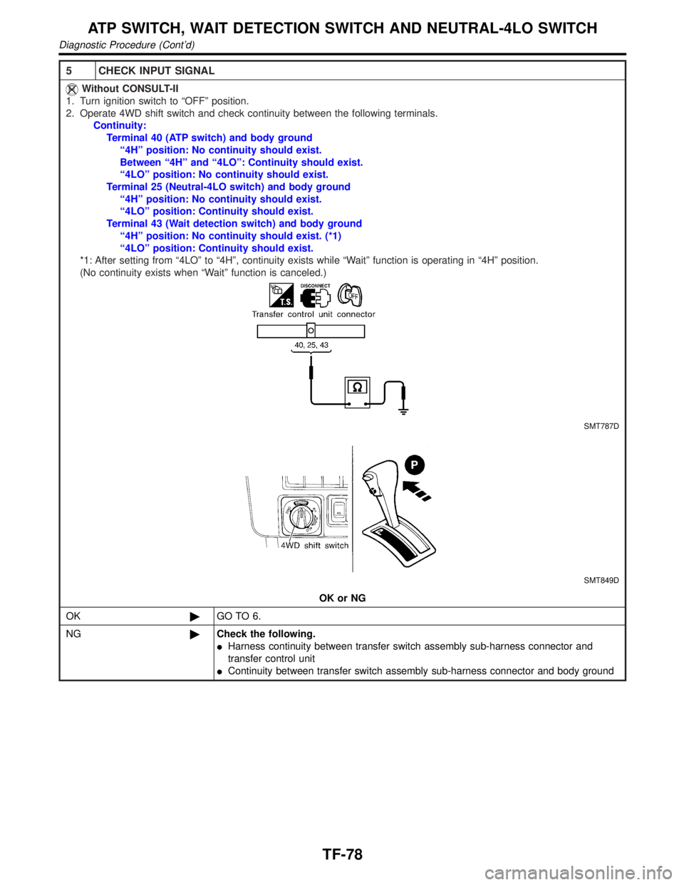
5 CHECK INPUT SIGNAL
Without CONSULT-II
1. Turn ignition switch to ªOFFº position.
2. Operate 4WD shift switch and check continuity between the following terminals.
Continuity:
Terminal 40 (ATP switch) and body ground
ª4Hº position: No continuity should exist.
Between ª4Hº and ª4LOº: Continuity should exist.
ª4LOº position: No continuity should exist.
Terminal 25 (Neutral-4LO switch) and body ground
ª4Hº position: No continuity should exist.
ª4LOº position: Continuity should exist.
Terminal 43 (Wait detection switch) and body ground
ª4Hº position: No continuity should exist. (*1)
ª4LOº position: Continuity should exist.
*1: After setting from ª4LOº to ª4Hº, continuity exists while ªWaitº function is operating in ª4Hº position.
(No continuity exists when ªWaitº function is canceled.)
SMT787D
SMT849D
OK or NG
OK©GO TO 6.
NG©Check the following.
IHarness continuity between transfer switch assembly sub-harness connector and
transfer control unit
IContinuity between transfer switch assembly sub-harness connector and body ground
ATP SWITCH, WAIT DETECTION SWITCH AND NEUTRAL-4LO SWITCH
Diagnostic Procedure (Cont'd)
TF-78
Page 2314 of 2395
6 PERFORM SELF-DIAGNOSIS AGAIN
After driving for a while, perform self-diagnosis again.
Refer to ªTrouble Diagnosis without CONSULT-IIº, TF-27.
OK or NG
OK©INSPECTION END
NG©1. Perform transfer control unit input/output signal inspection. Refer to ªTRANSFER
CONTROL UNIT INSPECTION TABLEº, ªTROUBLE DIAGNOSIS Ð GENERAL
DESCRIPTIONº, TF-55.
2. If NG, recheck transfer control unit pin terminals for damage or loose connection with
harness connector.GI
MA
EM
LC
EC
FE
AT
PD
AX
SU
BR
ST
RS
BT
HA
SC
EL
IDX
ATP SWITCH, WAIT DETECTION SWITCH AND NEUTRAL-4LO SWITCH
Diagnostic Procedure (Cont'd)
TF-79
Page 2316 of 2395
5 CHECK INPUT SIGNAL
With CONSULT-II
1. Turn ignition switch to ªONº position.
2. Select ªECU INPUT SIGNALSº in Data Monitor.
3. Read out ON/OFF status of ªCL PRES SWº.
SMT788D
SMT977D
OK or NG
OK©GO TO 7.
NG©Check the following.
IContinuity between transfer control unit and transfer terminal cord assembly sub-har-
ness connector
ITransfer sub-harness
IClutch pressure switch
Refer to ª4WD Solenoid Valve, Clutch Pressure Switch and Line Pressure Switchº,
ªCOMPONENT INSPECTIONº, TF-111.
GI
MA
EM
LC
EC
FE
AT
PD
AX
SU
BR
ST
RS
BT
HA
SC
EL
IDX
CLUTCH PRESSURE SWITCH
Diagnostic Procedure (Cont'd)
TF-81
Page 2317 of 2395

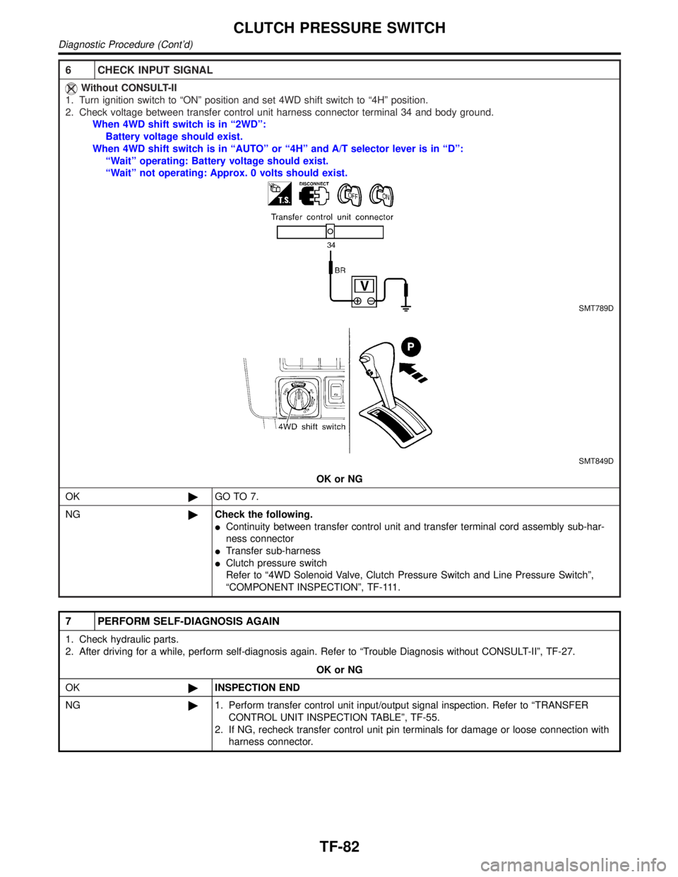
6 CHECK INPUT SIGNAL
Without CONSULT-II
1. Turn ignition switch to ªONº position and set 4WD shift switch to ª4Hº position.
2. Check voltage between transfer control unit harness connector terminal 34 and body ground.
When 4WD shift switch is in ª2WDº:
Battery voltage should exist.
When 4WD shift switch is in ªAUTOº or ª4Hº and A/T selector lever is in ªDº:
ªWaitº operating: Battery voltage should exist.
ªWaitº not operating: Approx. 0 volts should exist.
SMT789D
SMT849D
OK or NG
OK©GO TO 7.
NG©Check the following.
IContinuity between transfer control unit and transfer terminal cord assembly sub-har-
ness connector
ITransfer sub-harness
IClutch pressure switch
Refer to ª4WD Solenoid Valve, Clutch Pressure Switch and Line Pressure Switchº,
ªCOMPONENT INSPECTIONº, TF-111.
7 PERFORM SELF-DIAGNOSIS AGAIN
1. Check hydraulic parts.
2. After driving for a while, perform self-diagnosis again. Refer to ªTrouble Diagnosis without CONSULT-IIº, TF-27.
OK or NG
OK©INSPECTION END
NG©1. Perform transfer control unit input/output signal inspection. Refer to ªTRANSFER
CONTROL UNIT INSPECTION TABLEº, TF-55.
2. If NG, recheck transfer control unit pin terminals for damage or loose connection with
harness connector.
CLUTCH PRESSURE SWITCH
Diagnostic Procedure (Cont'd)
TF-82
Page 2319 of 2395
4 CHECK INPUT SIGNAL
SMT790D
With CONSULT-II
1. Select ªECU INPUT SIGNALSº in Data Monitor.
2. Read out the ON/OFF status of ªLINE PRES SWº.
SMT977D
OK or NG
OK©GO TO 6.
NG©Check the following.
IContinuity between transfer control unit and transfer terminal cord assembly sub-har-
ness connector
ITransfer sub-harness
ILine pressure switch
Refer to ª4WD Solenoid Valve, Clutch Pressure Switch and Line Pressure Switchº,
ªCOMPONENT INSPECTIONº, TF-111.
LINE PRESSURE SWITCH
Diagnostic Procedure (Cont'd)
TF-84
Page 2320 of 2395

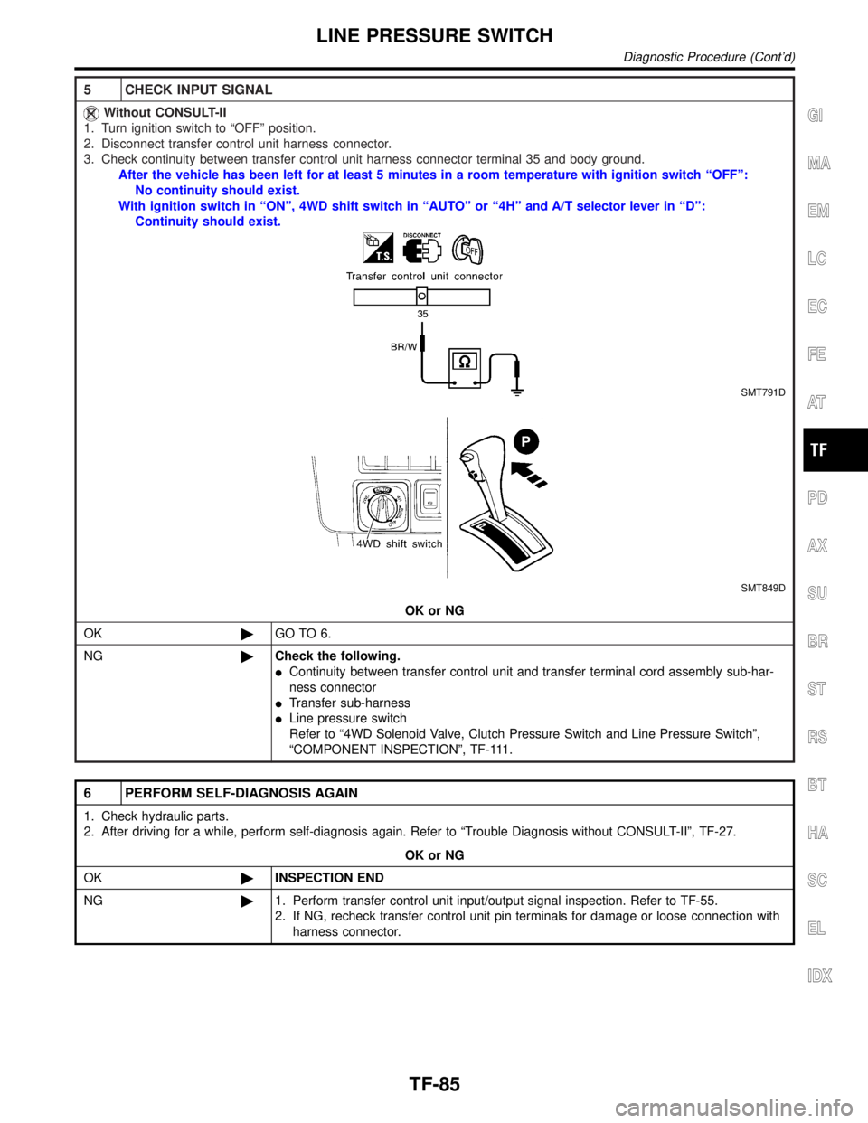
5 CHECK INPUT SIGNAL
Without CONSULT-II
1. Turn ignition switch to ªOFFº position.
2. Disconnect transfer control unit harness connector.
3. Check continuity between transfer control unit harness connector terminal 35 and body ground.
After the vehicle has been left for at least 5 minutes in a room temperature with ignition switch ªOFFº:
No continuity should exist.
With ignition switch in ªONº, 4WD shift switch in ªAUTOº or ª4Hº and A/T selector lever in ªDº:
Continuity should exist.
SMT791D
SMT849D
OK or NG
OK©GO TO 6.
NG©Check the following.
IContinuity between transfer control unit and transfer terminal cord assembly sub-har-
ness connector
ITransfer sub-harness
ILine pressure switch
Refer to ª4WD Solenoid Valve, Clutch Pressure Switch and Line Pressure Switchº,
ªCOMPONENT INSPECTIONº, TF-111.
6 PERFORM SELF-DIAGNOSIS AGAIN
1. Check hydraulic parts.
2. After driving for a while, perform self-diagnosis again. Refer to ªTrouble Diagnosis without CONSULT-IIº, TF-27.
OK or NG
OK©INSPECTION END
NG©1. Perform transfer control unit input/output signal inspection. Refer to TF-55.
2. If NG, recheck transfer control unit pin terminals for damage or loose connection with
harness connector.
GI
MA
EM
LC
EC
FE
AT
PD
AX
SU
BR
ST
RS
BT
HA
SC
EL
IDX
LINE PRESSURE SWITCH
Diagnostic Procedure (Cont'd)
TF-85