Page 701 of 2395
Wiring DiagramNBEC0067
MEC944C
DTC P0110 INTAKE AIR TEMPERATURE SENSOR
Wiring Diagram
EC-166
Page 702 of 2395
Diagnostic ProcedureNBEC0068
1 CHECK INTAKE AIR TEMPERATURE SENSOR POWER SUPPLY CIRCUIT
1. Turn ignition switch ªOFFº.
2. Disconnect intake air temperature sensor harness connector.
SEF962Y
3. Turn ignition switch ªONº.
4. Check voltage between terminal 1 and ground.
SEF301X
OK or NG
OK©GO TO 3.
NG©GO TO 2.
2 DETECT MALFUNCTIONING PART
Check the following.
IHarness connectors E1, M1
IHarness connectors M33, F22
IHarness for open or short between ECM and intake air temperature sensor
©Repair harness or connectors.
3 CHECK INTAKE AIR TEMPERATURE SENSOR GROUND CIRCUIT FOR OPEN AND SHORT
1. Turn ignition switch ªOFFº.
2. Check harness continuity between sensor terminal 2 and engine ground.
Refer to Wiring Diagram.
Continuity should exist.
3. Also check harness for short to power.
OK or NG
OK©GO TO 5.
NG©GO TO 4.
GI
MA
EM
LC
FE
AT
TF
PD
AX
SU
BR
ST
RS
BT
HA
SC
EL
IDX
DTC P0110 INTAKE AIR TEMPERATURE SENSOR
Diagnostic Procedure
EC-167
Page 706 of 2395
Wiring DiagramNBEC0072
MEC945C
GI
MA
EM
LC
FE
AT
TF
PD
AX
SU
BR
ST
RS
BT
HA
SC
EL
IDX
DTC P0115 ENGINE COOLANT TEMPERATURE SENSOR (ECTS) (CIRCUIT)
Wiring Diagram
EC-171
Page 707 of 2395
Diagnostic ProcedureNBEC0073
1 CHECK ECTS POWER SUPPLY CIRCUIT
1. Turn ignition switch ªOFFº.
2. Disconnect engine coolant temperature sensor (ECTS) harness connector F112, F28.
SEF370Z
3. Turn ignition switch ªONº.
4. Check voltage between ECTS harness connector F28 terminal 3 and ground with CONSULT-II or tester.
SEF371Z
OK or NG
OK©GO TO 3.
NG©GO TO 2.
2 DETECT MALFUNCTIONING PART
Check the following.
IHarness connectors F112, F28
IHarness for open or short between ECM and engine coolant temperature sensor
©Repair harness or connectors.
3 CHECK ECTS GROUND CIRCUIT FOR OPEN AND CIRCUIT
1. Turn ignition switch ªOFFº.
2. Check harness continuity between ECTS terminal 2 and engine ground.
Refer to Wiring Diagram.
Continuity should exist.
3. Also check harness for short to power.
OK or NG
OK©GO TO 5.
NG©GO TO 4.
DTC P0115 ENGINE COOLANT TEMPERATURE SENSOR (ECTS) (CIRCUIT)
Diagnostic Procedure
EC-172
Page 715 of 2395
Wiring DiagramNBEC0079
MEC946C
DTC P0120 THROTTLE POSITION SENSOR
Wiring Diagram
EC-180
Page 717 of 2395

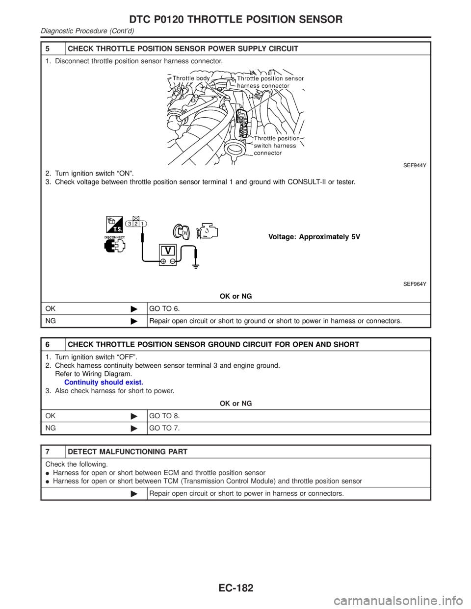
5 CHECK THROTTLE POSITION SENSOR POWER SUPPLY CIRCUIT
1. Disconnect throttle position sensor harness connector.
SEF944Y
2. Turn ignition switch ªONº.
3. Check voltage between throttle position sensor terminal 1 and ground with CONSULT-II or tester.
SEF964Y
OK or NG
OK©GO TO 6.
NG©Repair open circuit or short to ground or short to power in harness or connectors.
6 CHECK THROTTLE POSITION SENSOR GROUND CIRCUIT FOR OPEN AND SHORT
1. Turn ignition switch ªOFFº.
2. Check harness continuity between sensor terminal 3 and engine ground.
Refer to Wiring Diagram.
Continuity should exist.
3. Also check harness for short to power.
OK or NG
OK©GO TO 8.
NG©GO TO 7.
7 DETECT MALFUNCTIONING PART
Check the following.
IHarness for open or short between ECM and throttle position sensor
IHarness for open or short between TCM (Transmission Control Module) and throttle position sensor
©Repair open circuit or short to power in harness or connectors.
DTC P0120 THROTTLE POSITION SENSOR
Diagnostic Procedure (Cont'd)
EC-182
Page 718 of 2395

8 CHECK THROTTLE POSITION SENSOR INPUT SIGNAL CIRCUIT FOR OPEN AND SHORT
1. Disconnect ECM harness connector.
2. Check harness continuity between ECM terminal 91 and throttle position sensor terminal 2.
Refer to Wiring Diagram.
Continuity should exist.
3. Also check harness for short to ground and short to power.
OK or NG
OK (With CONSULT-II)©GO TO 9.
OK (Without CONSULT-
II)©GO TO 10.
NG©Repair open circuit or short to ground or short to power in harness or connectors.
9 CHECK THROTTLE POSITION SENSOR
With CONSULT-II
1. Start engine and warm it up to normal operating temperature.
2. Stop engine (ignition switch OFF).
3. Remove the vacuum hose connected to the throttle opener.
4. Connect suitable vacuum hose to the vacuum pump and the opener.
5. Apply vacuum [more than ±40.0kPa (±300mmHg, ±11.81inHg)] until the throttle drum becomes free from the rod of the
throttle opener.
SEF793W
6. Turn ignition switch ON.
7. Select ªDATA MONITORº mode with CONSULT-II.
8. Check voltage of ªTHRTL POS SENº under the following conditions.
Voltage measurement must be made with throttle position sensor installed in vehicle.
SEF062Y
OK or NG
OK©GO TO 12.
NG©GO TO 11.
GI
MA
EM
LC
FE
AT
TF
PD
AX
SU
BR
ST
RS
BT
HA
SC
EL
IDX
DTC P0120 THROTTLE POSITION SENSOR
Diagnostic Procedure (Cont'd)
EC-183
Page 724 of 2395
Wiring DiagramNBEC0084
MEC945C
GI
MA
EM
LC
FE
AT
TF
PD
AX
SU
BR
ST
RS
BT
HA
SC
EL
IDX
DTC P0125 ENGINE COOLANT TEMPERATURE SENSOR (ECTS)
Wiring Diagram
EC-189