Page 1 of 88
Introduction 2
Instrumentation 6
Controls and features 13
Starting 18
Driving 23
Roadside emergencies 34
Maintenance and care 52
Capacities and specifications 80
Reporting Safety Defects 80
Index 84
All rights reserved. Reproduction by any means, electronic or mechanical
including photocopying, recording or by any information storage and retrieval
system or translation in whole or part is not permitted without written
authorization from Ford Motor Company. Ford may change the contents without
notice and without incurring obligation.
Copyright 2000 Ford Motor Company
Table of contents
1
Page 8 of 88

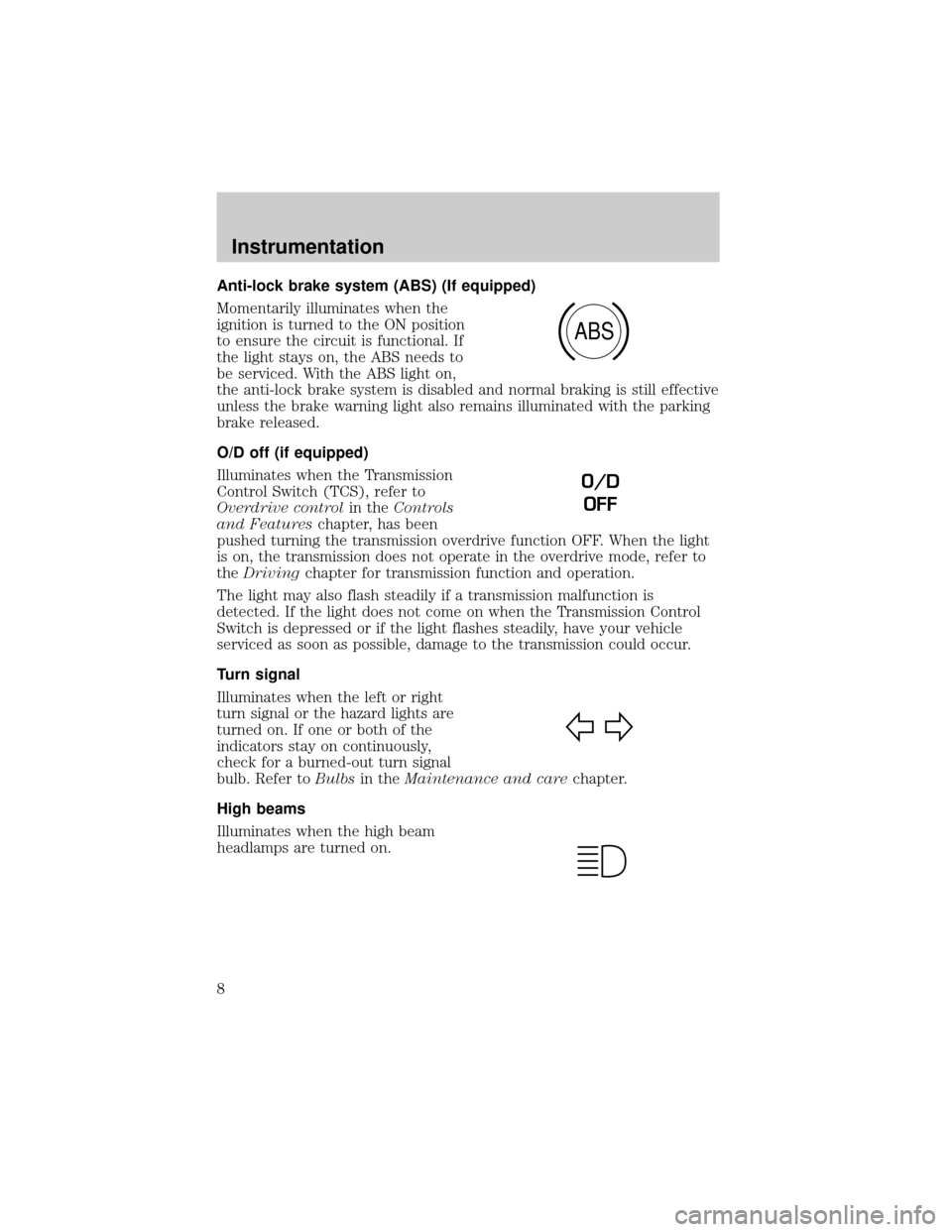
Anti-lock brake system (ABS) (If equipped)
Momentarily illuminates when the
ignition is turned to the ON position
to ensure the circuit is functional. If
the light stays on, the ABS needs to
be serviced. With the ABS light on,
the anti-lock brake system is disabled and normal braking is still effective
unless the brake warning light also remains illuminated with the parking
brake released.
O/D off (if equipped)
Illuminates when the Transmission
Control Switch (TCS), refer to
Overdrive controlin theControls
and Featureschapter, has been
pushed turning the transmission overdrive function OFF. When the light
is on, the transmission does not operate in the overdrive mode, refer to
theDrivingchapter for transmission function and operation.
The light may also flash steadily if a transmission malfunction is
detected. If the light does not come on when the Transmission Control
Switch is depressed or if the light flashes steadily, have your vehicle
serviced as soon as possible, damage to the transmission could occur.
Turn signal
Illuminates when the left or right
turn signal or the hazard lights are
turned on. If one or both of the
indicators stay on continuously,
check for a burned-out turn signal
bulb. Refer toBulbsin theMaintenance and carechapter.
High beams
Illuminates when the high beam
headlamps are turned on.
ABS
O/D
OFF
Instrumentation
8
Page 10 of 88

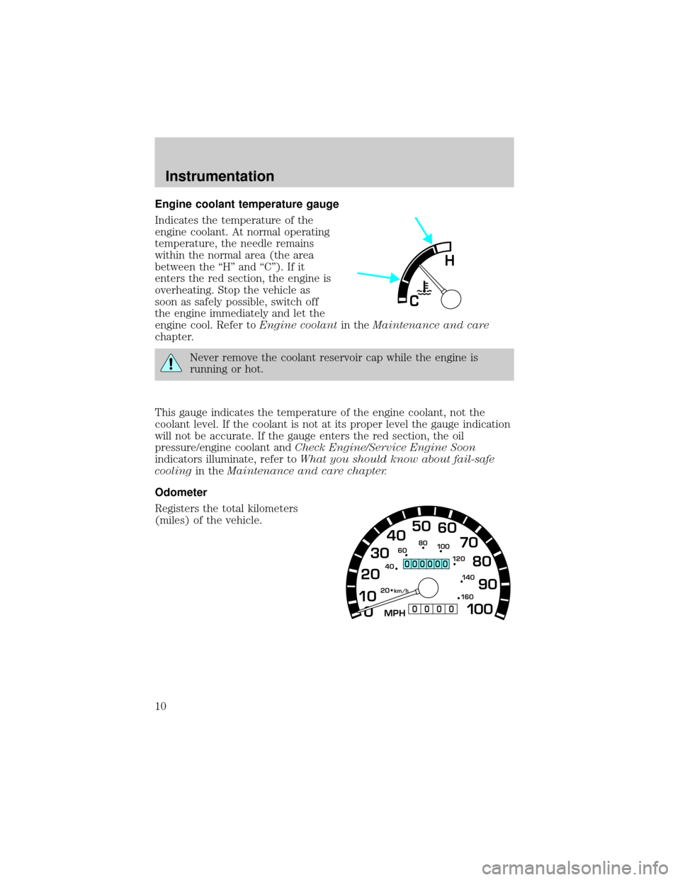
Engine coolant temperature gauge
Indicates the temperature of the
engine coolant. At normal operating
temperature, the needle remains
within the normal area (the area
between the ªHº and ªCº). If it
enters the red section, the engine is
overheating. Stop the vehicle as
soon as safely possible, switch off
the engine immediately and let the
engine cool. Refer toEngine coolantin theMaintenance and care
chapter.
Never remove the coolant reservoir cap while the engine is
running or hot.
This gauge indicates the temperature of the engine coolant, not the
coolant level. If the coolant is not at its proper level the gauge indication
will not be accurate. If the gauge enters the red section, the oil
pressure/engine coolant andCheck Engine/Service Engine Soon
indicators illuminate, refer toWhat you should know about fail-safe
coolingin theMaintenance and care chapter.
Odometer
Registers the total kilometers
(miles) of the vehicle.
H
C
0 1020304050
60
70
80
90
10 0
20 km/h
406080
10 0
12 0
14 0
16 0
MPH
000000
0000
Instrumentation
10
Page 11 of 88
Trip odometer
Registers the kilometers (miles) of
individual journeys. To reset,
depress the control.
Battery voltage gauge
This shows the battery voltage when
the ignition is in the ON position. If
the pointer moves and stays outside
the normal operating range (as
indicated by arrows), have the
vehicle's electrical system checked
as soon as possible.
Engine oil pressure gauge
This shows the engine oil pressure
in the system. Sufficient pressure
exists as long as the needle remains
in the normal range (the area
between the ªLº and ªHº).
If the gauge indicates low pressure,
stop the vehicle as soon as safely
possible and switch off the engine
immediately. Check the oil level.
Add oil if needed (refer toEngine
oilin theMaintenance and care
chapter). If the oil level is correct, have your vehicle checked at your
dealership or by a qualified technician.
0 1020304050
60
70
80
90
10 0
20 km/h
406080
10 0
12 0
14 0
16 0
MPH
000000
0000
18
8
H
L
Instrumentation
11
Page 23 of 88

BRAKES
Your service brakes are self-adjusting. Refer to the scheduled
maintenance guide for scheduled maintenance.
Occasional brake noise is normal and often does not indicate a
performance concern with the vehicle's brake system. In normal
operation, automotive brake systems may emit occasional or intermittent
squeal or groan noises when the brakes are applied. Such noises are
usually heard during the first few brake applications in the morning;
however, they may be heard at any time while braking and can be
aggravated by environmental conditions such as cold, heat, moisture,
road dust, salt or mud. If a ªmetal-to-metal,º ªcontinuous grindingº or
ªcontinuous squealº sound is present while braking, the brake linings
may be worn-out and should be inspected by a qualified service
technician.
Four-wheel anti-lock brake system (ABS)
This vehicle is equipped with an anti-lock braking system (ABS). A noise
from the hydraulic pump motor and pulsation in the pedal may be
observed during ABS braking events. Pedal pulsation coupled with noise
while braking under panic conditions or on loose gravel, bumps, wet or
snowy roads is normal and indicates proper functioning of the vehicle's
anti-lock brake system. The ABS performs a self-check after you start
the engine and begin to drive away. A brief mechanical noise may be
heard during this test. This is normal. If a malfunction is found, the ABS
warning light will come on. If the vehicle has continuous vibration or
shudder in the steering wheel while braking, the vehicle should be
inspected by a qualified service technician.
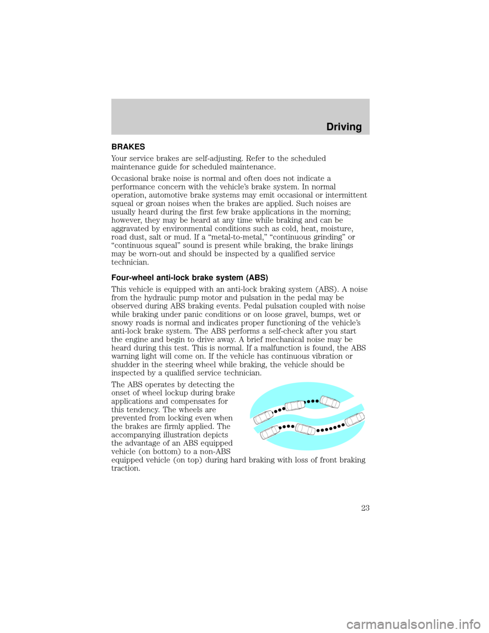
The ABS operates by detecting the
onset of wheel lockup during brake
applications and compensates for
this tendency. The wheels are
prevented from locking even when
the brakes are firmly applied. The
accompanying illustration depicts
the advantage of an ABS equipped
vehicle (on bottom) to a non-ABS
equipped vehicle (on top) during hard braking with loss of front braking
traction.
Driving
23
Page 38 of 88
Always disconnect the battery before servicing high current
fuses.
Always replace the cover to the Power Distribution Box before
reconnecting the battery or refilling fluid reservoirs.
If the battery has been disconnected and reconnected, refer to the
Batterysection of theMaintenance and carechapter.
The high-current fuses are coded as follows:
Fuse/Relay
LocationFuse Amp
RatingPower Distribution Box Description
1 20A**4 x 4 System
2 30A** EEC Power
3 20A** Fuel System
4 30A** Headlamps
5 50A** ABS System
6 30A** ABS System
7 Ð Not Used
8 Ð Not Used
9 40A** Blower Motor
10 Ð Not Used
11 Ð Not Used
12 Ð Not Used
13 60A** I/P Fuse Panel
14 50A** Ignition
1 15A* Parking Lamps
14
175A
13
12
10 9
87
6
65
5 4
4 3
3 2
21
1 11109 11
8
476
21
35
D10DE2
Roadside emergencies
38
Page 52 of 88

SERVICE RECOMMENDATIONS
To help you service your vehicle:
²We highlight do-it-yourself items in the engine compartment for easy
location.
²We provide a scheduled maintenance guide which makes tracking
routine service easy.
If your vehicle requires professional service, your dealership can provide
the necessary parts and service. Check your ªWarranty Guideº to find out
which parts and services are covered.
Use only recommended fuels, lubricants, fluids and service parts
conforming to specifications. Motorcraft parts are designed and built to
provide the best performance in your vehicle.
PRECAUTIONS WHEN SERVICING YOUR VEHICLE
Be especially careful when inspecting or servicing your vehicle.
²Do not work on a hot engine.
²When the engine is running, make sure that loose clothing, jewelry or
long hair does not get caught up in moving parts.
²Do not work on a vehicle with the engine running in an enclosed
space, unless you are sure you have enough ventilation.
²Keep all lit cigarettes, open flames and other lit material away from
the battery and all fuel related parts.
If you disconnect the battery, the engine must ªrelearnº its idle
conditions before your vehicle will drive properly, as explained inBattery
in this chapter.
Working with the engine off
1. Set the parking brake and ensure the gearshift is securely latched in P
(Park).
2. Turn off the engine and remove the key.
3. Block the wheels to prevent the vehicle from moving unexpectedly.
Working with the engine on
1. Set the parking brake and ensure the gearshift is securely latched in P
(Park).
2. Block the wheels to prevent the vehicle from moving unexpectedly.
Maintenance and care
52
Page 53 of 88
Do not start your engine with the air cleaner removed and do
not remove it while the engine is running.
IDENTIFYING COMPONENTS IN THE ENGINE COMPARTMENT
4.0L SOHC V6 ENGINE
1. Windshield washer fluid reservoir
2. Power distribution box
3. Brake fluid reservoir
4. Engine oil dipstick
5. Automatic transmission fluid dipstick
6. Engine oil filler cap
7. Battery
8. Radiator cap
9. Power steering fluid reservoir
10
123456
978
Maintenance and care
53