Page 146 of 240

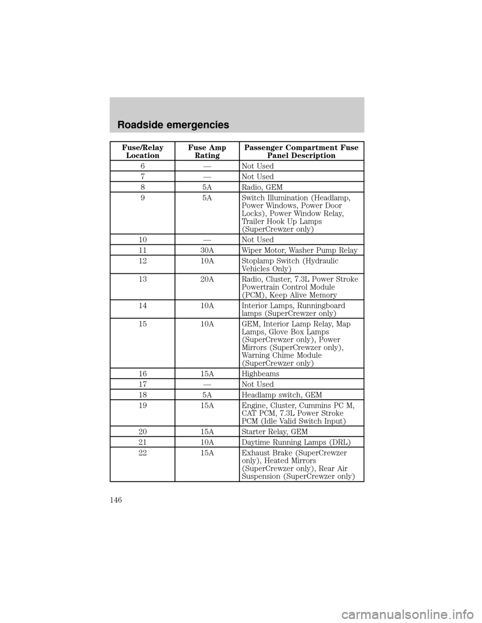
Fuse/Relay
LocationFuse Amp
RatingPassenger Compartment Fuse
Panel Description
6 Ð Not Used
7 Ð Not Used
8 5A Radio, GEM
9 5A Switch Illumination (Headlamp,
Power Windows, Power Door
Locks), Power Window Relay,
Trailer Hook Up Lamps
(SuperCrewzer only)
10 Ð Not Used
11 30A Wiper Motor, Washer Pump Relay
12 10A Stoplamp Switch (Hydraulic
Vehicles Only)
13 20A Radio, Cluster, 7.3L Power Stroke
Powertrain Control Module
(PCM), Keep Alive Memory
14 10A Interior Lamps, Runningboard
lamps (SuperCrewzer only)
15 10A GEM, Interior Lamp Relay, Map
Lamps, Glove Box Lamps
(SuperCrewzer only), Power
Mirrors (SuperCrewzer only),
Warning Chime Module
(SuperCrewzer only)
16 15A Highbeams
17 Ð Not Used
18 5A Headlamp switch, GEM
19 15A Engine, Cluster, Cummins PC M,
CAT PCM, 7.3L Power Stroke
PCM (Idle Valid Switch Input)
20 15A Starter Relay, GEM
21 10A Daytime Running Lamps (DRL)
22 15A Exhaust Brake (SuperCrewzer
only), Heated Mirrors
(SuperCrewzer only), Rear Air
Suspension (SuperCrewzer only)
Roadside emergencies
146
Page 148 of 240

Power distribution box
The power distribution box is located in the engine compartment. The
power distribution box contains high-current fuses that protect your
vehicle's main electrical systems from overloads.
Always disconnect the battery before servicing high current fuses.
Always replace the cover to the Power Distribution Box before
reconnecting the battery or refilling fluid reservoirs.
If the battery has been disconnected and reconnected, refer to the
Batterysection of theMaintenance and carechapter.
The high-current fuses and relays are coded as follows.
Fuse/Relay
LocationFuse Amp
RatingPower Distribution Box
Description
1 15A* Park Lamps, Roof Lamps
2 25A* Cummins Powertrain Control
Module (PCM)
15A* Foglamps (SuperCrewzer only)
3 10A* Generator
4 15A* Washer Pump
503
304
303
302301
502
501
207201
202
203
204122118114110106102
121117113109105101
120116112108104
119115111107103
24
209206
208
18161412108642
1715131197531
205
23
22
21
401
20
19
Roadside emergencies
148
Page 154 of 240

JUMP STARTING YOUR VEHICLE
The gases around the battery can explode if exposed to flames,
sparks, or lit cigarettes. An explosion could result in injury or
vehicle damage.
Do not push start your vehicle. You could damage the catalytic
converter.
Batteries contain sulfuric acid which burns skin, eyes, and
clothing.
Preparing your vehicle
Also see the label on the battery.
1. Use only a 12±volt supply to start your vehicle. If you connect your
battery to a 24±volt power supply you can damage your starter, ignition
system and other electrical components. Do not attach the jumper cables
to the glow plug relay as this could severely damage the glow plugs,
injector driver module and PCM.
2. Do not disconnect the battery of the disabled vehicle as this could
damage the vehicle's electrical system.
3. Park the booster vehicle close to the disabled vehicle making sure
theydo nottouch. Set the parking brake on both vehicles and stay clear
of the engine cooling fan and other moving parts.
4. Check all battery terminals and remove any excessive corrosion before
you attach the battery cables.
5. Turn the heater fan on in both vehicles to protect any electrical
surges. Turn all other accessories off.
Roadside emergencies
154
Page 155 of 240

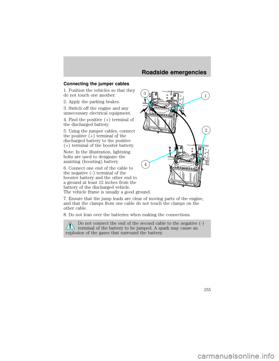
Connecting the jumper cables
1. Position the vehicles so that they
do not touch one another.
2. Apply the parking brakes.
3. Switch off the engine and any
unnecessary electrical equipment.
4. Find the positive (+) terminal of
the discharged battery.
5. Using the jumper cables, connect
the positive (+) terminal of the
discharged battery to the positive
(+) terminal of the booster battery.
Note: In the illustration, lightning
bolts are used to designate the
assisting (boosting) battery.
6. Connect one end of the cable to
the negative (-) terminal of the
booster battery and the other end to
a ground at least 12 inches from the
battery of the discharged vehicle.
The vehicle frame is usually a good ground.
7. Ensure that the jump leads are clear of moving parts of the engine,
and that the clamps from one cable do not touch the clamps on the
other cable.
8. Do not lean over the batteries when making the connections.
Do not connect the end of the second cable to the negative (-)
terminal of the battery to be jumped. A spark may cause an
explosion of the gases that surround the battery.
13
2
4
Roadside emergencies
155
Page 156 of 240
Jump starting
1. Start the booster vehicle and run the engine at moderately increased
speed.
2. After a few minutes, start the engine of the vehicle with the
discharged battery.
3. After starting, run the engine at about 1,000 RPM for 3±5 minutes.
Do not operate the starter longer than 30 seconds. Wait at least
two minutes between starting attempts to allow the starter to
cool. If the engine does not start after several attempts, call for
road service.
Removing the jumper cables
1. Remove the ground connection
from the disabled vehicle first,
followed by the cable on the
negative (-) battery terminal of the
booster vehicle.
2. Remove the cable from the
positive (+) terminal of the
discharged battery and then from
the positive (+) terminal of the
booster battery.
3. After the disabled vehicle has
been started, allow it to idle for a
while so the engine can ªrelearnº its
idle conditions.
42
3
1
Roadside emergencies
156
Page 158 of 240
CHECKING UNDER THE HOOD
Opening the hood
The hood and fenders are held in position by a latch located on each
fender.
The parking brake must be fully set before opening the hood or
possible personal injury may occur.
If you must leave the engine running while checking under the
hood, do not allow any loose clothing, jewelry, hair or other
items to get near moving engine components or possible personal
injury may occur.
To open the hood:
1. Set the parking brake, shift into N (Neutral) (automatic transmission)
or 1 (First) (manual transmission) and turn the engine off.
2. Lift upward on the bottom of
each latch.
3. Pull the bottom of each latch
away from the fender.
Maintenance and care
158
Page 159 of 240
4. Tilt the hood forward until
stopped by the retaining cables.
To lower the hood:
1. Push the hood rearward at the top center of the hood above the grille
until closed.
2. Engage the latch on each fender.
3. Push down on the bottom of each latch until locked.
To avoid the possibility of personal injury, never stand beneath
the hood when it is being raised or lowered.
ENGINE OIL
Checking engine oil levelÐCummins B and Caterpillar 3126 B engines
Refer to the appropriate engine operator's manual for information on the
engine oil.
Maintenance and care
159
Page 160 of 240

Checking engine oil levelÐ7.3L Power Stroke engine
Refer to the Scheduled Maintenance Guide for the appropriate intervals
for checking the engine oil.
Check the engine oil level consistently and accurately. The following
procedure is recommended:
1. Start the engine and let it run until it reaches normal operating
temperature (the engine coolant temperature gauge indicator will be
near the center of the normal area between H and C).
2. Park the vehicle on level ground.
3. Set the parking brake and shift into N (Neutral) (automatic
transmission) or 1 (First) (manual transmission).
4. Turn off the engine and wait a few minutes for the oil to drain
completely into the oil pan.
5. Open the hood. Protect yourself from engine heat.
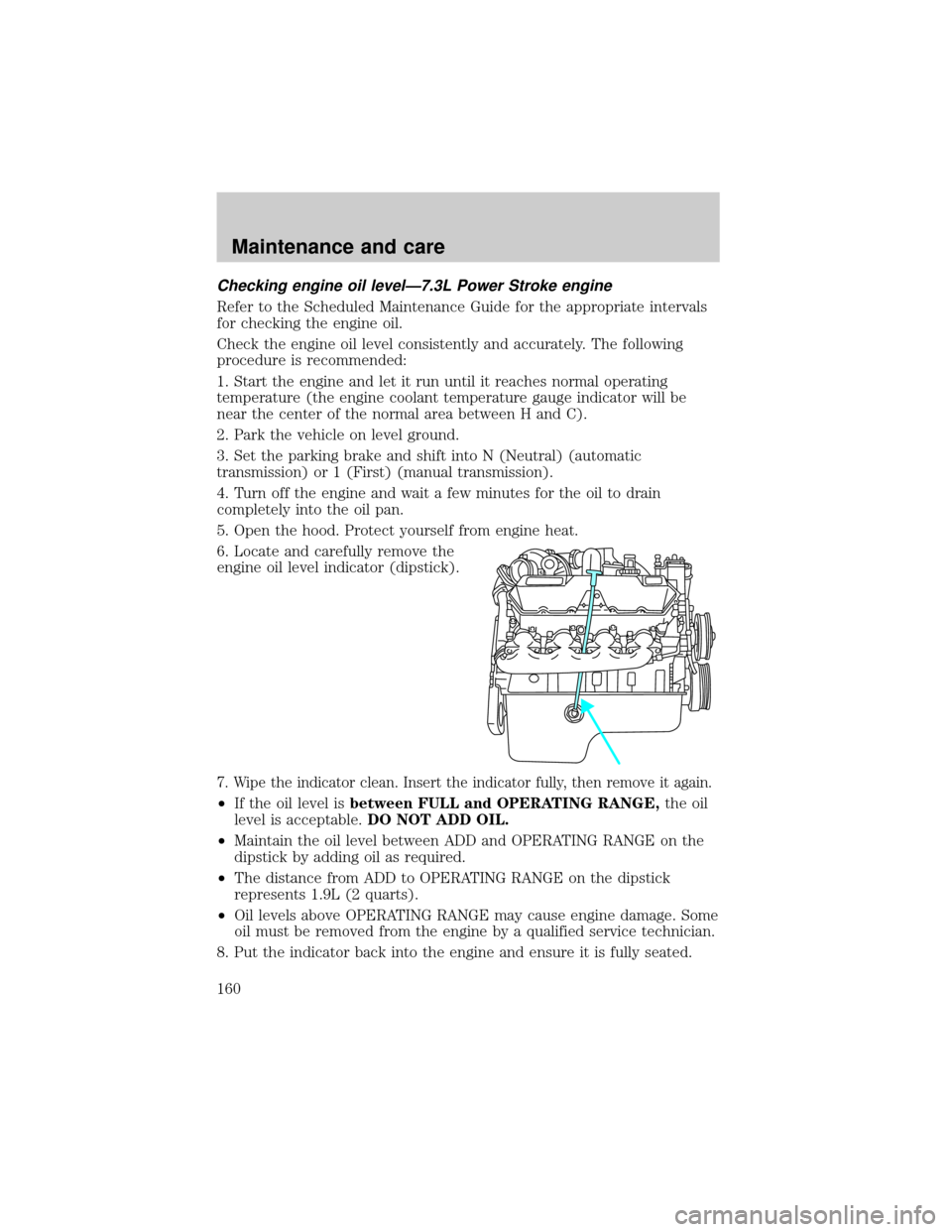
6. Locate and carefully remove the
engine oil level indicator (dipstick).
7. Wipe the indicator clean. Insert the indicator fully, then remove it again.
²If the oil level isbetween FULL and OPERATING RANGE,the oil
level is acceptable.DO NOT ADD OIL.
²Maintain the oil level between ADD and OPERATING RANGE on the
dipstick by adding oil as required.
²The distance from ADD to OPERATING RANGE on the dipstick
represents 1.9L (2 quarts).
²Oil levels above OPERATING RANGE may cause engine damage. Some
oil must be removed from the engine by a qualified service technician.
8. Put the indicator back into the engine and ensure it is fully seated.
Maintenance and care
160