Page 20 of 248
Trip odometer
Registers the kilometers (miles) of
individual journeys. To reset,
depress the control.
Refer toElectronic Message Centerfor Trip A and Trip B features on
the optional instrument cluster.
Engine coolant temperature gauge
Indicates the temperature of the engine coolant. At normal operating
temperature, the needle remains within the normal area (the area
between the ªHº and ªCº). If it enters the red section, the engine is
overheating. Stop the vehicle as soon as safely possible, switch off the
ignition and let it cool. Refer toEngine coolantin theMaintenance
and carechapter.
Never remove the coolant reservoir cap while the engine is
running or hot.
²Standard instrument cluster
MPH km/h10 203040506070
80
90
10 0
11 0
12 0
20 406080100
120
140
160
180
200
0000000
0 0 0 0
TEMPH
C
Instrumentation
20
Page 21 of 248
²Optional instrument cluster
This gauge indicates the temperature of the engine coolant, not the
coolant level. If the coolant is not at its proper level the gauge indication
will not be accurate. If the gauge enters the red section, the engine
coolant andCheck Engine/Service Engine Soonindicators illuminate,
refer toWhat you should know about fail-safe coolingin the
Maintenance and carechapter.
Battery voltage gauge (if equipped)
This shows the battery voltage when
the ignition is in the ON position. If
the pointer moves and stays outside
the normal operating range (as
indicated), have the vehicle's
electrical system checked as soon as
possible.
N
O
R
M
H
C
VOLTSH
L
Instrumentation
21
Page 23 of 248
Selectable features
Reset
Press this control to reset the
selected message center function to
zero. The only functions which can
be reset are:
²AVG ECON
²TRIP A or TRIP B
²AVG SPEED
E/M
Press this control to switch the
electronic instrument cluster display
and the message center display from
metric to English units.
Select
Each press of the SELECT control
will select a different function.
²Press the right side of the control
to advance the function to the
right.
²Press the left side of the control
to advance the function to the
left.
To reset any function:
1. Push either the right or left side of the SELECT control to choose the
desired function.
RESET E/M SELECT
RESET E/M SELECT
RESET E/M SELECT
Instrumentation
23
Page 34 of 248

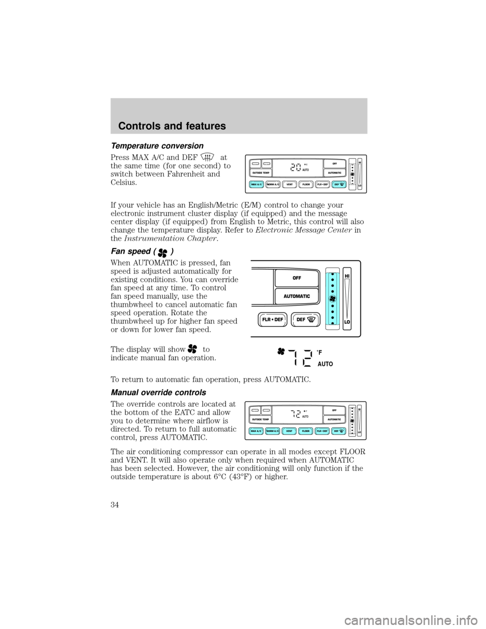
Temperature conversion
Press MAX A/C and DEFat
the same time (for one second) to
switch between Fahrenheit and
Celsius.
If your vehicle has an English/Metric (E/M) control to change your
electronic instrument cluster display (if equipped) and the message
center display (if equipped) from English to Metric, this control will also
change the temperature display. Refer toElectronic Message Centerin
theInstrumentation Chapter.
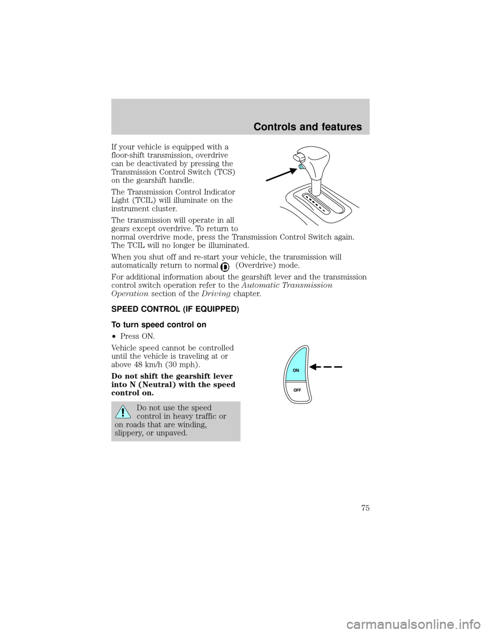
Fan speed ()
When AUTOMATIC is pressed, fan
speed is adjusted automatically for
existing conditions. You can override
fan speed at any time. To control
fan speed manually, use the
thumbwheel to cancel automatic fan
speed operation. Rotate the
thumbwheel up for higher fan speed
or down for lower fan speed.
The display will show
to
indicate manual fan operation.
To return to automatic fan operation, press AUTOMATIC.
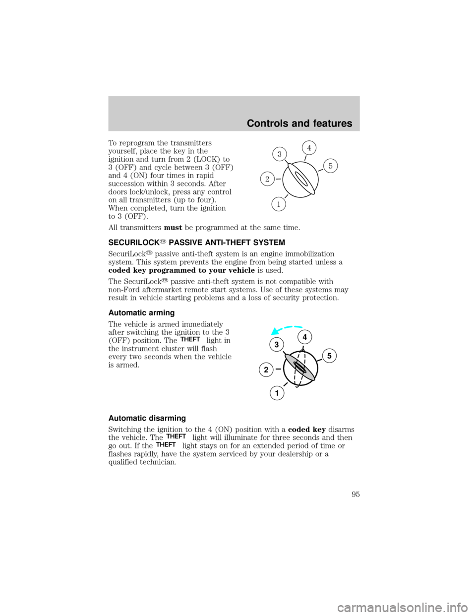
Manual override controls
The override controls are located at
the bottom of the EATC and allow
you to determine where airflow is
directed. To return to full automatic
control, press AUTOMATIC.
The air conditioning compressor can operate in all modes except FLOOR
and VENT. It will also operate only when required when AUTOMATIC
has been selected. However, the air conditioning will only function if the
outside temperature is about 6ÉC (43ÉF) or higher.
NORM A/CVENT FLOOR FLR • DEF DEF
HI
LO
MAX A/C
OUTSIDE TEMP AUTOMATICOFFAUTO
FLR • DEFDEF
HI
LO
AUTOMATICOFF
˚F
AUTO
NORM A/CVENT FLOOR FLR • DEF DEF
HI
LO
MAX A/C
OUTSIDE TEMP AUTOMATICOFF
FAUTO
Controls and features
34
Page 75 of 248

If your vehicle is equipped with a
floor-shift transmission, overdrive
can be deactivated by pressing the
Transmission Control Switch (TCS)
on the gearshift handle.
The Transmission Control Indicator
Light (TCIL) will illuminate on the
instrument cluster.
The transmission will operate in all
gears except overdrive. To return to
normal overdrive mode, press the Transmission Control Switch again.
The TCIL will no longer be illuminated.
When you shut off and re-start your vehicle, the transmission will
automatically return to normal
(Overdrive) mode.
For additional information about the gearshift lever and the transmission
control switch operation refer to theAutomatic Transmission
Operationsection of theDrivingchapter.
SPEED CONTROL (IF EQUIPPED)
To turn speed control on
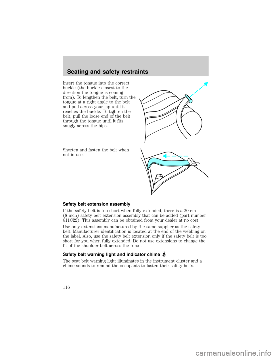
²Press ON.
Vehicle speed cannot be controlled
until the vehicle is traveling at or
above 48 km/h (30 mph).
Do not shift the gearshift lever
into N (Neutral) with the speed
control on.
Do not use the speed
control in heavy traffic or
on roads that are winding,
slippery, or unpaved.
Controls and features
75
Page 95 of 248

To reprogram the transmitters
yourself, place the key in the
ignition and turn from 2 (LOCK) to
3 (OFF) and cycle between 3 (OFF)
and 4 (ON) four times in rapid
succession within 3 seconds. After
doors lock/unlock, press any control
on all transmitters (up to four).
When completed, turn the ignition
to 3 (OFF).
All transmittersmustbe programmed at the same time.
SECURILOCKYPASSIVE ANTI-THEFT SYSTEM
SecuriLockypassive anti-theft system is an engine immobilization
system. This system prevents the engine from being started unless a
coded key programmed to your vehicleis used.
The SecuriLockypassive anti-theft system is not compatible with
non-Ford aftermarket remote start systems. Use of these systems may
result in vehicle starting problems and a loss of security protection.
Automatic arming
The vehicle is armed immediately
after switching the ignition to the 3
(OFF) position. The
THEFTlight in
the instrument cluster will flash
every two seconds when the vehicle
is armed.
Automatic disarming
Switching the ignition to the 4 (ON) position with acoded keydisarms
the vehicle. The
THEFTlight will illuminate for three seconds and then
go out. If theTHEFTlight stays on for an extended period of time or
flashes rapidly, have the system serviced by your dealership or a
qualified technician.
3
1
2
5
4
3
2
1
5
4
Controls and features
95
Page 110 of 248

Front safety belt usage sensors
The front safety belt usage sensors detect whether or not the driver and
front outboard passenger safety belts are fastened. This information
allows your Personal Safety System to tailor the air bag deployment and
safety belt pretensioner activation depending upon safety belt usage.
Refer toSafety Beltsection in this chapter.
Front safety belt pretensioners
The safety belt pretensioners are designed to tighten the safety belts
firmly against the occupant's body during a collision. This maximizes the
effectiveness of the safety belts and helps properly position the occupant
relative to the air bag to improve protection. The safety belt
pretensioners can be either activated alone or, if the collision is of
sufficient severity, together with the air bags.
Front safety belt energy management retractors
The front safety belt energy management retractors allow webbing to be
pulled out of the retractor in a gradual and controlled manner in
response to the occupant's forward momentum. This helps reduce the
risk of force-related injuries to the occupant's chest by limiting the load
on the occupant. Refer toSafety Beltsection in this chapter.
Determining if the Personal Safety System is operational
The Personal Safety System uses a warning light in the instrument
cluster or a back-up tone to indicate the condition of the system. Refer
to theWarning Lightsection in theInstrument Clusterchapter.
Routine maintenance of the Personal Safety System is not required.
The Restraints Control Module (RCM) monitors its own internal circuits
and the circuits for the air bag supplemental restraints, crash sensor(s),
safety belt pretensioners, front safety belt buckle sensors, driver seat
position sensor, and passenger occupant classification sensor (if
equipped). In addition, the RCM also monitors the restraints warning
light in the instrument cluster. A difficulty with the system is indicated
by one or more of the following.
²The warning light will either flash or stay lit.
²The warning light will not illuminate immediately after ignition is
turned on.
²A series of five beeps will be heard. The tone pattern will repeat
periodically until the problem and warning light are repaired.
Seating and safety restraints
110
Page 116 of 248

Insert the tongue into the correct
buckle (the buckle closest to the
direction the tongue is coming
from). To lengthen the belt, turn the
tongue at a right angle to the belt
and pull across your lap until it
reaches the buckle. To tighten the
belt, pull the loose end of the belt
through the tongue until it fits
snugly across the hips.
Shorten and fasten the belt when
not in use.
Safety belt extension assembly
If the safety belt is too short when fully extended, there is a 20 cm
(8 inch) safety belt extension assembly that can be added (part number
611C22). This assembly can be obtained from your dealer at no cost.
Use only extensions manufactured by the same supplier as the safety
belt. Manufacturer identification is located at the end of the webbing on
the label. Also, use the safety belt extension only if the safety belt is too
short for you when fully extended. Do not use extensions to change the
fit of the shoulder belt across the torso.
Safety belt warning light and indicator chime
The seat belt warning light illuminates in the instrument cluster and a
chime sounds to remind the occupants to fasten their safety belts.
Seating and safety restraints
116