Page 117 of 248
Conditions of operation
If... Then...
The driver's safety belt is not
buckled before the ignition switch
is turned to the ON position...The safety belt warning light
illuminates 1-2 minutes and the
warning chime sounds 4-8
seconds.
The driver's safety belt is buckled
while the indicator light is
illuminated and the warning chime
is sounding...The safety belt warning light and
warning chime turn off.
The driver's safety belt is buckled
before the ignition switch is turned
to the ON position...The safety belt warning light and
indicator chime remain off.
Belt minder
The Belt Minder feature is a supplemental warning to the safety belt
warning function. This feature provides additional reminders to the
driver that the driver's safety belt is unbuckled by intermittently
sounding a chime and illuminating the safety belt warning lamp in the
instrument cluster.
If... Then...
The driver's safety belt is not
buckled approximately 5 seconds
after the safety belt warning light
has turned off...The Belt Minder feature is
activated - the safety belt warning
light illuminates and the warning
chime sounds for 6 seconds every
30 seconds, repeating for
approximately 5 minutes or until
safety belt is buckled.
The driver's safety belt is buckled
while the safety belt indicator light
is illuminated and the safety belt
warning chime is sounding...The Belt Minder feature will not
activate.
The driver's safety belt is buckled
before the ignition switch is turned
to the ON position...The Belt Minder feature will not
activate.
The purpose of the Belt Minder is to remind occasional wearers to wear
safety belts all of the time.
Seating and safety restraints
117
Page 125 of 248
If the air bag has deployed,the air bag will not function
again and must be replaced immediately.If the air bag is not
replaced, the unrepaired area will increase the risk of injury in a
collision.
Determining if the system is operational
The SRS uses a readiness light in the instrument cluster or a tone to
indicate the condition of the system. Refer to theAir bag readiness
section in theInstrumentationchapter. Routine maintenance of the air
bag is not required.
A difficulty with the system is indicated by one or more of the following:
²The readiness light will either
flash or stay lit.
²The readiness light will not
illuminate immediately after
ignition is turned on.
²A series of five beeps will be heard. The tone pattern will repeat
periodically until the problem and/or light are repaired.
If any of these things happen, even intermittently, have the SRS serviced
at your dealership or by a qualified technician immediately. Unless
serviced, the system may not function properly in the event of a
collision.
Disposal of air bags and air bag equipped vehicles
(including pretensioners)
For disposal of air bags or air bag equipped vehicles, see your local
dealership or qualified technician. Air bags MUST BE disposed of by
qualified personnel.
SAFETY RESTRAINTS FOR CHILDREN
See the following sections for directions on how to properly use safety
restraints for children. Also seeAir Bag Supplemental Restraint
System (SRS)in this chapter for special instructions about using air
bags.
AIR
BAG
Seating and safety restraints
125
Page 139 of 248
ABS warning lampABS
TheABSwarning lamp in the instrument cluster momentarily illuminates
when the ignition is turned to the ON position. If the light does not
illuminate momentarily at start up, remains on or continues to flash, the
ABS needs to be serviced.
With the ABS light on, the anti-lock
brake system is disabled and normal
braking is still effective unless the
brake warning light also remains
illuminated with parking brake
released. (If your brake warning lamp illuminates, have your vehicle
serviced immediately.)
Using ABS
²In an emergency or when maximum efficiency from the four-wheel
ABS is required, apply continuous force on the brake. The four wheel
ABS will be activated immediately, thus allowing you to retain full
steering control of your vehicle and, providing there is sufficient
space, will enable you to avoid obstacles and bring the vehicle to a
controlled stop.
²The anti-lock system does not decrease the time necessary to apply
the brakes or always reduce stopping distance. Always leave enough
room between your vehicle and the vehicle in front of you to stop.
²We recommend that you familiarize yourself with this braking
technique. However, avoid taking any unnecessary risks.
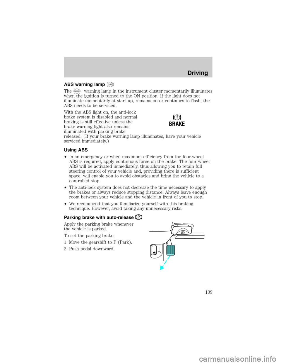
Parking brake with auto-release
Apply the parking brake whenever
the vehicle is parked.
To set the parking brake:
1. Move the gearshift to P (Park).
2. Push pedal downward.
!
BRAKE
HOOD
Driving
139
Page 140 of 248
The BRAKE warning lamp in the
instrument cluster illuminates and
remains illuminated (when the
ignition is turned ON) until the
parking brake is fully released.
Always set the parking brake fully and make sure the gearshift is
latched in P (Park). Turn off the ignition whenever you leave
your vehicle.
The parking brake is not recommended to stop a moving vehicle.
However, if the normal brakes fail, the parking brake can be used to stop
your vehicle in an emergency. Since the parking brake applies only the
rear brakes, the vehicle's stopping distance will increase greatly and the
handling of your vehicle will be adversely affected.
Your vehicle has an automatic parking brake release (except for
police/fleet vehicles which have the manual release). To release the
parking brake:
1. Turn the ignition to the ON position.
2. Press the brake pedal.
3. Move the gearshift from the P (Park) position to one of the forward
gears (the parking brake will not release automatically when you shift
into reverse). The brake pedal must remain pressed while the gearshift is
moved.
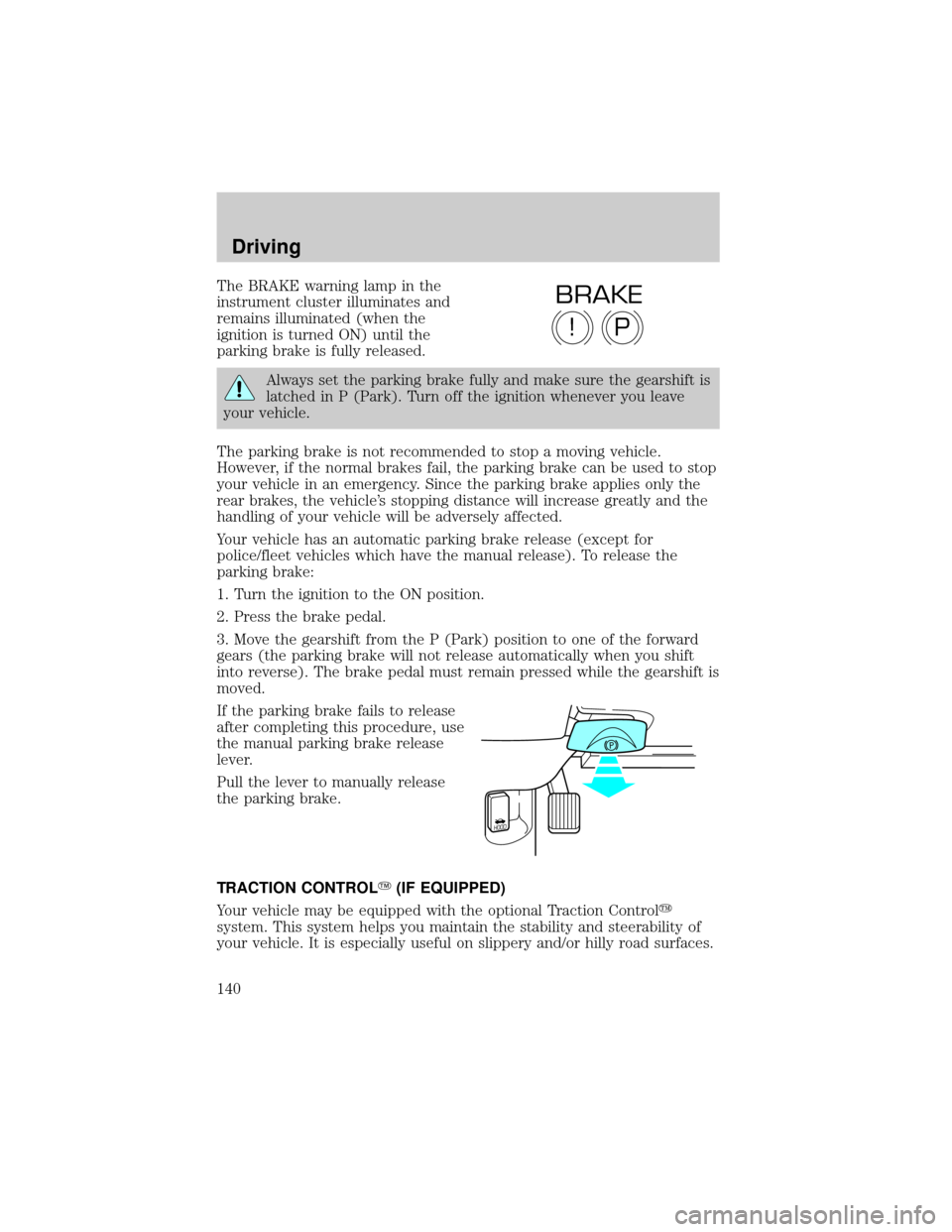
If the parking brake fails to release
after completing this procedure, use
the manual parking brake release
lever.
Pull the lever to manually release
the parking brake.
TRACTION CONTROLY(IF EQUIPPED)
Your vehicle may be equipped with the optional Traction Controly
system. This system helps you maintain the stability and steerability of
your vehicle. It is especially useful on slippery and/or hilly road surfaces.
P!
BRAKE
HOOD
Driving
140
Page 146 of 248
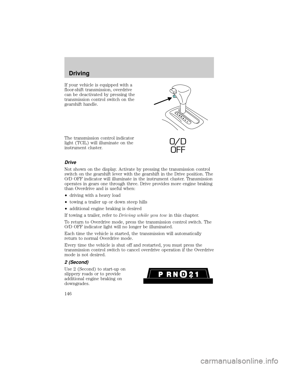
If your vehicle is equipped with a
floor-shift transmission, overdrive
can be deactivated by pressing the
transmission control switch on the
gearshift handle.
The transmission control indicator
light (TCIL) will illuminate on the
instrument cluster.
Drive
Not shown on the display. Activate by pressing the transmission control
switch on the gearshift lever with the gearshift in the Drive position. The
O/D OFF indicator will illuminate in the instrument cluster. Transmission
operates in gears one through three. Drive provides more engine braking
than Overdrive and is useful when:
²driving with a heavy load
²towing a trailer up or down steep hills
²additional engine braking is desired
If towing a trailer, refer toDriving while you towin this chapter.
To return to Overdrive mode, press the transmission control switch. The
O/D OFF indicator light will no longer be illuminated.
Each time the vehicle is started, the transmission will automatically
return to normal Overdrive mode.
Every time the vehicle is shut off and restarted, you must press the
transmission control switch to cancel overdrive operation if the Overdrive
mode is not desired.
2 (Second)
Use 2 (Second) to start-up on
slippery roads or to provide
additional engine braking on
downgrades.
O/ D
OFF
Driving
146
Page 157 of 248
Passenger compartment fuse panel
The fuse panel is located below and to the left of the steering wheel by
the brake pedal. Remove the panel cover to access the fuses.
To remove a fuse use the fuse puller tool provided on the fuse panel
cover.
The fuses are coded as follows.
Fuse/Relay
LocationFuse Amp
RatingPassenger Compartment Fuse Panel
Description
1 Ð Not Used
2 Ð Not Used
3 Ð Not Used
4 10A Air Bags
5 Ð Not Used
6 15A Instrument Cluster, Warning Lamps
Module, Transmission Control Switch,
Lighting Control Module (LCM)
7 Ð Not Used
27 25
26 2423 21
2219
20
18 16
17 1514 12
131030
32
31
28
29
11
97
8653
41
2
Roadside emergencies
157
Page 158 of 248
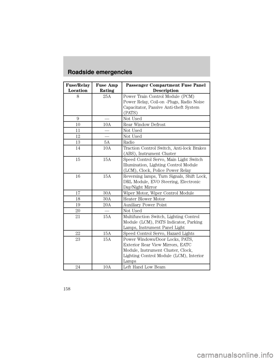
Fuse/Relay
LocationFuse Amp
RatingPassenger Compartment Fuse Panel
Description
8 25A Power Train Control Module (PCM)
Power Relay, Coil-on -Plugs, Radio Noise
Capacitator, Passive Anti-theft System
(PATS)
9 Ð Not Used
10 10A Rear Window Defrost
11 Ð Not Used
12 Ð Not Used
13 5A Radio
14 10A Traction Control Switch, Anti-lock Brakes
(ABS), Instrument Cluster
15 15A Speed Control Servo, Main Light Switch
Illumination, Lighting Control Module
(LCM), Clock, Police Power Relay
16 15A Reversing lamps, Turn Signals, Shift Lock,
DRL Module, EVO Steering, Electronic
Day/Night Mirror
17 30A Wiper Motor, Wiper Control Module
18 30A Heater Blower Motor
19 20A Auxiliary Power Point
20 Ð Not Used
21 15A Multifunction Switch, Lighting Control
Module (LCM), PATS Indicator, Parking
Lamps, Instrument Panel Light
22 15A Speed Control Servo, Hazard Lights
23 15A Power Windows/Door Locks, PATS,
Exterior Rear View Mirrors, EATC
Module, Instrument Cluster, Clock,
Lighting Control Module (LCM), Interior
Lamps
24 10A Left Hand Low Beam
Roadside emergencies
158
Page 218 of 248
²Cover the highlighted areas to prevent water damage when cleaning
the engine.
²Never wash or rinse the engine while it is running; water in the
running engine may cause internal damage.
Cleaning the instrument panel
Clean with a damp cloth, then dry with a dry cloth.
Avoid cleaner or polish that increases the gloss of the upper portion of
the instrument panel. The dull finish in this area helps protect the driver
from undesirable windshield reflection.
Do not use chemical solvents or strong detergents when cleaning
the steering wheel or instrument panel to avoid contamination of
the air bag system.
Cleaning the instrument cluster lens
Clean with a damp cloth, then dry with a dry cloth.
Do not use household or glass cleaners as these may damage the lens.
Maintenance and care
218