2001 DODGE TOWN AND COUNTRY instrument panel
[x] Cancel search: instrument panelPage 462 of 2321
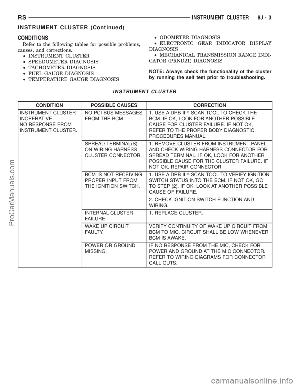
CONDITIONS
Refer to the following tables for possible problems,
causes, and corrections.
²INSTRUMENT CLUSTER
²SPEEDOMETER DIAGNOSIS
²TACHOMETER DIAGNOSIS
²FUEL GAUGE DIAGNOSIS
²TEMPERATURE GAUGE DIAGNOSIS²ODOMETER DIAGNOSIS
²ELECTRONIC GEAR INDICATOR DISPLAY
DIAGNOSIS
²MECHANICAL TRANSMISSION RANGE INDI-
CATOR (PRND21) DIAGNOSIS
NOTE: Always check the functionality of the cluster
by running the self test prior to troubleshooting.
INSTRUMENT CLUSTER
CONDITION POSSIBLE CAUSES CORRECTION
INSTRUMENT CLUSTER
INOPERATIVE.
NO RESPONSE FROM
INSTRUMENT CLUSTER.NO PCI BUS MESSAGES
FROM THE BCM.1. USE A DRB IIITSCAN TOOL TO CHECK THE
BCM. IF OK, LOOK FOR ANOTHER POSSIBLE
CAUSE FOR CLUSTER FAILURE. IF NOT OK,
REFER TO THE PROPER BODY DIAGNOSTIC
PROCEDURES MANUAL.
SPREAD TERMINAL(S)
ON WIRING HARNESS
CLUSTER CONNECTOR.1. REMOVE CLUSTER FROM INSTRUMENT PANEL
AND CHECK WIRING HARNESS CONNECTOR FOR
SPREAD TERMINAL. IF OK, LOOK FOR ANOTHER
POSSIBLE CAUSE FOR THE CLUSTER FAILURE. IF
NOT OK, REPAIR CONNECTOR.
BCM IS NOT RECEIVING
PROPER INPUT FROM
THE IGNITION SWITCH.1. USE A DRB IIITSCAN TOOL TO VERIFY IGNITION
SWITCH STATUS INTO THE BCM. IF NOT OK, GO
TO STEP (2). IF OK, LOOK AT ANOTHER POSSIBLE
CAUSE OF FAILURE.
2. CHECK IGNITION SWITCH FUNCTION AND
WIRING.
INTERNAL CLUSTER
FAILURE.1. REPLACE CLUSTER.
WAKE UP CIRCUIT
FAULTY.VERIFY CONTINUITY OF WAKE UP CIRCUIT FROM
BCM TO MIC. CIRCUIT SHALL BE LOW WHENEVER
BCM IS AWAKE.
POWER OR GROUND
MISSING.IF NO RESPONSE FROM THE MIC, CHECK FOR
POWER AND GROUND AT THE MIC CONNECTOR.
REFER TO WIRING DIAGRAMS FOR CONNECTOR
CALL OUTS.
RSINSTRUMENT CLUSTER8J-3
INSTRUMENT CLUSTER (Continued)
ProCarManuals.com
Page 463 of 2321

SPEEDOMETER DIAGNOSIS
CONDITION POSSIBLE CAUSES CORRECTION
NO POINTER
MOVEMENT1. INTERNAL CLUSTER
FAILURE.1.A. PERFORM CLUSTER SELF-DIAGNOSTIC TEST
AND CHECK FOR FAULT CODES.
²IF SPEEDOMETER POINTER MOVES TO
CALIBRATION POINTS DURING TEST LOOK FOR
ANOTHER POSSIBLE CAUSE OF FAILURE.
²IF THE POINTER DOESN'T MOVE DURING TEST,
CHECK FOR POWER AND GROUND TO THE MIC.
IF POWER AND GROUND ARE PRESENT GO TO
STEP 1.B.
1.B. REPLACE CLUSTER. GO TO STEP 1.C.
1.C. CONNECT CLUSTER INTO INSTRUMENT
PANEL WIRING HARNESS. PLACE IT BACK INTO
THE PROPER POSITION IN THE INSTRUMENT
PANEL. PUT IN THE TOP FOUR MOUNTING
SCREWS AND SECURE THE CLUSTER TO THE
INSTRUMENT PANEL.
2. NO SPEED PCI BUS
MESSAGE OR ZERO
MPH PCI SPEED BUS
MESSAGE.2.A. CHECK THE PCM (CODE 10) USING A DRB IIIT
SCAN TOOL. IF OK, GO TO STEP 2.B. IF NOT OK,
REFER TO THE PROPER ENGINE DIAGNOSTIC
PROCEDURES MANUAL TO REPAIR THE PCM.
2.B. CHECK THE SPEED SIGNAL INPUT INTO THE
PCM. THE SPEED SIGNAL ORIGINATES FROM ONE
OF THE FOLLOWING SOURCES:
²A DISTANCE SENSOR FOR VEHICLES WITH 3
SPEED AUTOMATIC TRANSMISSION. CHECK
CONTINUITY FROM DISTANCE SENSOR TO PCM.
IF OK, REPLACE DISTANCE SENSOR. IF NOT OK,
REPAIR WIRING.
²THE TCM FOR VEHICLES WITH THE 4 SPEED
ELECTRONIC TRANSMISSIONS. CHECK
CONTINUITY FROM TCM TO PCM. IF OK, USE A
DRB IIITSCAN TOOL TO CHECK TCM. REFER TO
THE PROPER TRANSMISSION DIAGNOSTIC
PROCEDURES MANUAL TO REPAIR THE TCM. IF
NOT OK, REPAIR WIRING.
8J - 4 INSTRUMENT CLUSTERRS
INSTRUMENT CLUSTER (Continued)
ProCarManuals.com
Page 470 of 2321
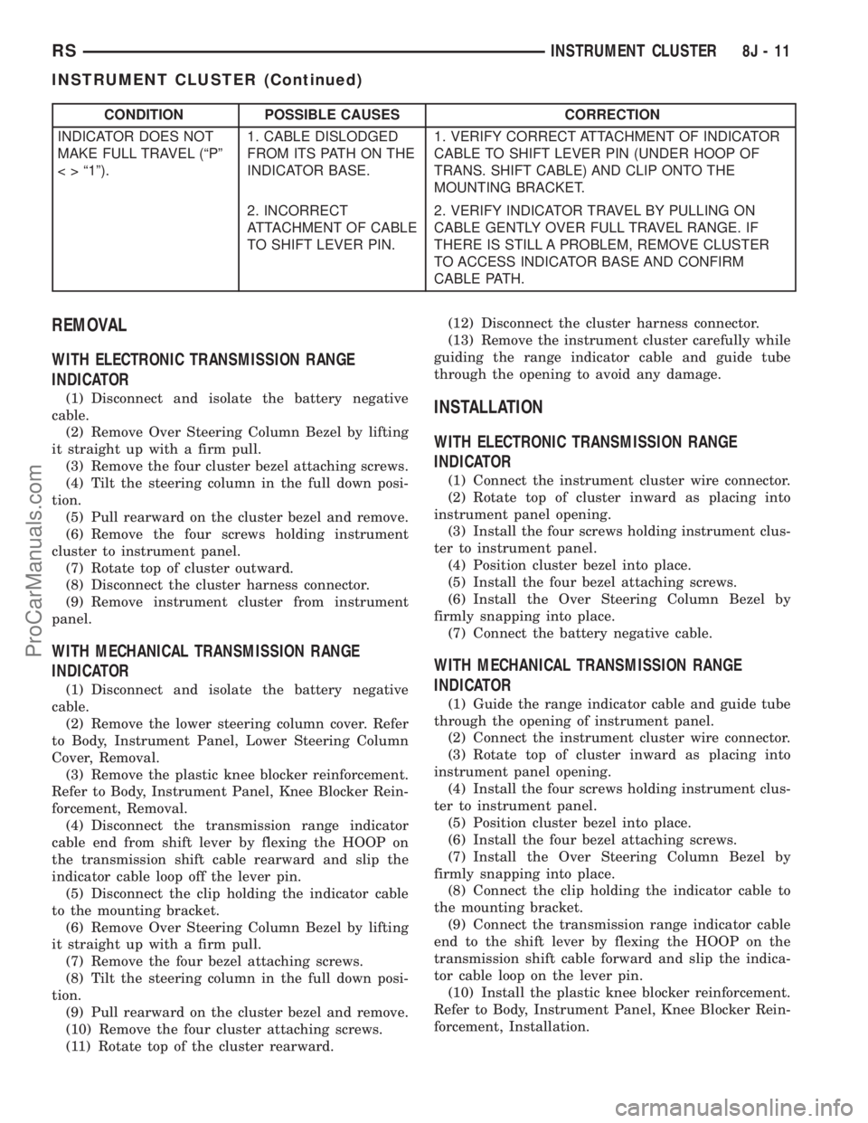
CONDITION POSSIBLE CAUSES CORRECTION
INDICATOR DOES NOT
MAKE FULL TRAVEL (ªPº
< > ª1º).1. CABLE DISLODGED
FROM ITS PATH ON THE
INDICATOR BASE.1. VERIFY CORRECT ATTACHMENT OF INDICATOR
CABLE TO SHIFT LEVER PIN (UNDER HOOP OF
TRANS. SHIFT CABLE) AND CLIP ONTO THE
MOUNTING BRACKET.
2. INCORRECT
ATTACHMENT OF CABLE
TO SHIFT LEVER PIN.2. VERIFY INDICATOR TRAVEL BY PULLING ON
CABLE GENTLY OVER FULL TRAVEL RANGE. IF
THERE IS STILL A PROBLEM, REMOVE CLUSTER
TO ACCESS INDICATOR BASE AND CONFIRM
CABLE PATH.
REMOVAL
WITH ELECTRONIC TRANSMISSION RANGE
INDICATOR
(1) Disconnect and isolate the battery negative
cable.
(2) Remove Over Steering Column Bezel by lifting
it straight up with a firm pull.
(3) Remove the four cluster bezel attaching screws.
(4) Tilt the steering column in the full down posi-
tion.
(5) Pull rearward on the cluster bezel and remove.
(6) Remove the four screws holding instrument
cluster to instrument panel.
(7) Rotate top of cluster outward.
(8) Disconnect the cluster harness connector.
(9) Remove instrument cluster from instrument
panel.
WITH MECHANICAL TRANSMISSION RANGE
INDICATOR
(1) Disconnect and isolate the battery negative
cable.
(2) Remove the lower steering column cover. Refer
to Body, Instrument Panel, Lower Steering Column
Cover, Removal.
(3) Remove the plastic knee blocker reinforcement.
Refer to Body, Instrument Panel, Knee Blocker Rein-
forcement, Removal.
(4) Disconnect the transmission range indicator
cable end from shift lever by flexing the HOOP on
the transmission shift cable rearward and slip the
indicator cable loop off the lever pin.
(5) Disconnect the clip holding the indicator cable
to the mounting bracket.
(6) Remove Over Steering Column Bezel by lifting
it straight up with a firm pull.
(7) Remove the four bezel attaching screws.
(8) Tilt the steering column in the full down posi-
tion.
(9) Pull rearward on the cluster bezel and remove.
(10) Remove the four cluster attaching screws.
(11) Rotate top of the cluster rearward.(12) Disconnect the cluster harness connector.
(13) Remove the instrument cluster carefully while
guiding the range indicator cable and guide tube
through the opening to avoid any damage.
INSTALLATION
WITH ELECTRONIC TRANSMISSION RANGE
INDICATOR
(1) Connect the instrument cluster wire connector.
(2) Rotate top of cluster inward as placing into
instrument panel opening.
(3) Install the four screws holding instrument clus-
ter to instrument panel.
(4) Position cluster bezel into place.
(5) Install the four bezel attaching screws.
(6) Install the Over Steering Column Bezel by
firmly snapping into place.
(7) Connect the battery negative cable.
WITH MECHANICAL TRANSMISSION RANGE
INDICATOR
(1) Guide the range indicator cable and guide tube
through the opening of instrument panel.
(2) Connect the instrument cluster wire connector.
(3) Rotate top of cluster inward as placing into
instrument panel opening.
(4) Install the four screws holding instrument clus-
ter to instrument panel.
(5) Position cluster bezel into place.
(6) Install the four bezel attaching screws.
(7) Install the Over Steering Column Bezel by
firmly snapping into place.
(8) Connect the clip holding the indicator cable to
the mounting bracket.
(9) Connect the transmission range indicator cable
end to the shift lever by flexing the HOOP on the
transmission shift cable forward and slip the indica-
tor cable loop on the lever pin.
(10) Install the plastic knee blocker reinforcement.
Refer to Body, Instrument Panel, Knee Blocker Rein-
forcement, Installation.
RSINSTRUMENT CLUSTER8J-11
INSTRUMENT CLUSTER (Continued)
ProCarManuals.com
Page 471 of 2321
(11) Install the lower steering column cover. Refer
to Body, Instrument Panel, Lower Steering Column
Cover, Installation.
(12) Connect the battery negative cable.
CLUSTER LENS
REMOVAL
(1) Remove the instrument cluster. Refer to Elec-
trical, Instrument Cluster, Removal.
(2) Remove the screws holding the lens to the
instrument cluster.
(3) Press down on the snap features of the lens
and remove the lens from the cluster.
INSTALLATION
(1) Insert the lens snap features into the cluster.
(2) Install the screws holding the lens to the
instrument cluster.
(3) Install the instrument cluster. Refer to Electri-
cal, Instrument Cluster, Installation.
MECHANICAL TRANSMISSION
RANGE INDICATOR
REMOVAL
(1) Remove the instrument cluster and disconnect
the range indicator cable at both attaching points.
Refer to Electrical, Instrument Cluster, Removal.
(2) From the backside of the cluster, remove two
screws holding the mechanical transmission rangeindicator and then remove it fromt instrument clus-
ter.
INSTALLATION
(1) Insert the mechanical transmission range indi-
cator into the backside of the instrument cluster and
install the two screws.
(2) Install the instrument cluster. Refer to Electri-
cal, Instrument Cluster, Installation.
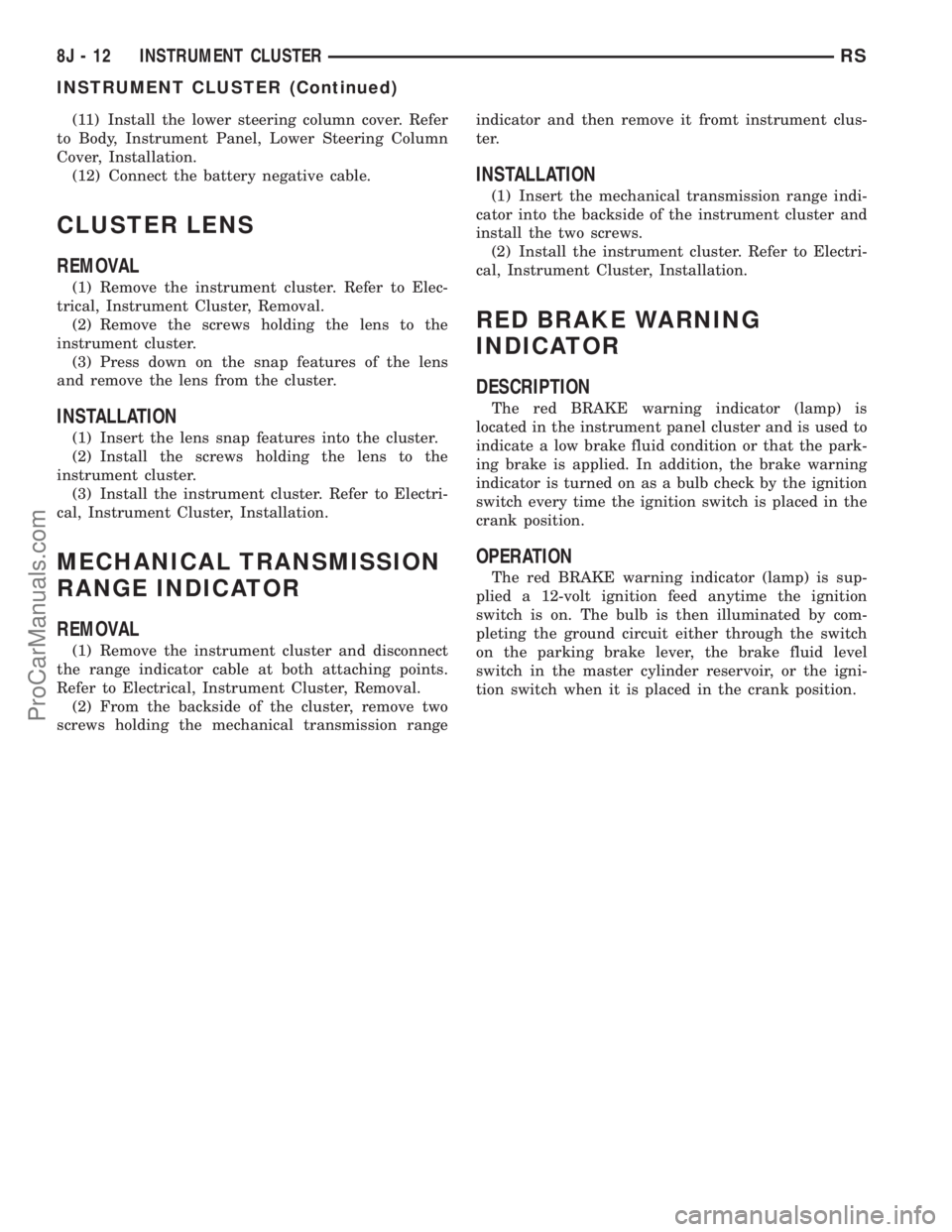
RED BRAKE WARNING
INDICATOR
DESCRIPTION
The red BRAKE warning indicator (lamp) is
located in the instrument panel cluster and is used to
indicate a low brake fluid condition or that the park-
ing brake is applied. In addition, the brake warning
indicator is turned on as a bulb check by the ignition
switch every time the ignition switch is placed in the
crank position.
OPERATION
The red BRAKE warning indicator (lamp) is sup-
plied a 12-volt ignition feed anytime the ignition
switch is on. The bulb is then illuminated by com-
pleting the ground circuit either through the switch
on the parking brake lever, the brake fluid level
switch in the master cylinder reservoir, or the igni-
tion switch when it is placed in the crank position.
8J - 12 INSTRUMENT CLUSTERRS
INSTRUMENT CLUSTER (Continued)
ProCarManuals.com
Page 484 of 2321
HEADLAMP
REMOVAL
(1)Disconnect and isolate the battery negative cable.
(2) Remove headlamp unit retaining screws.
(3) Remove headlamp unit to expose back of unit.
(4) Remove wiring connector from bulb.
(5) Rotate headlamp bulb retaining ring counter-
clockwise.
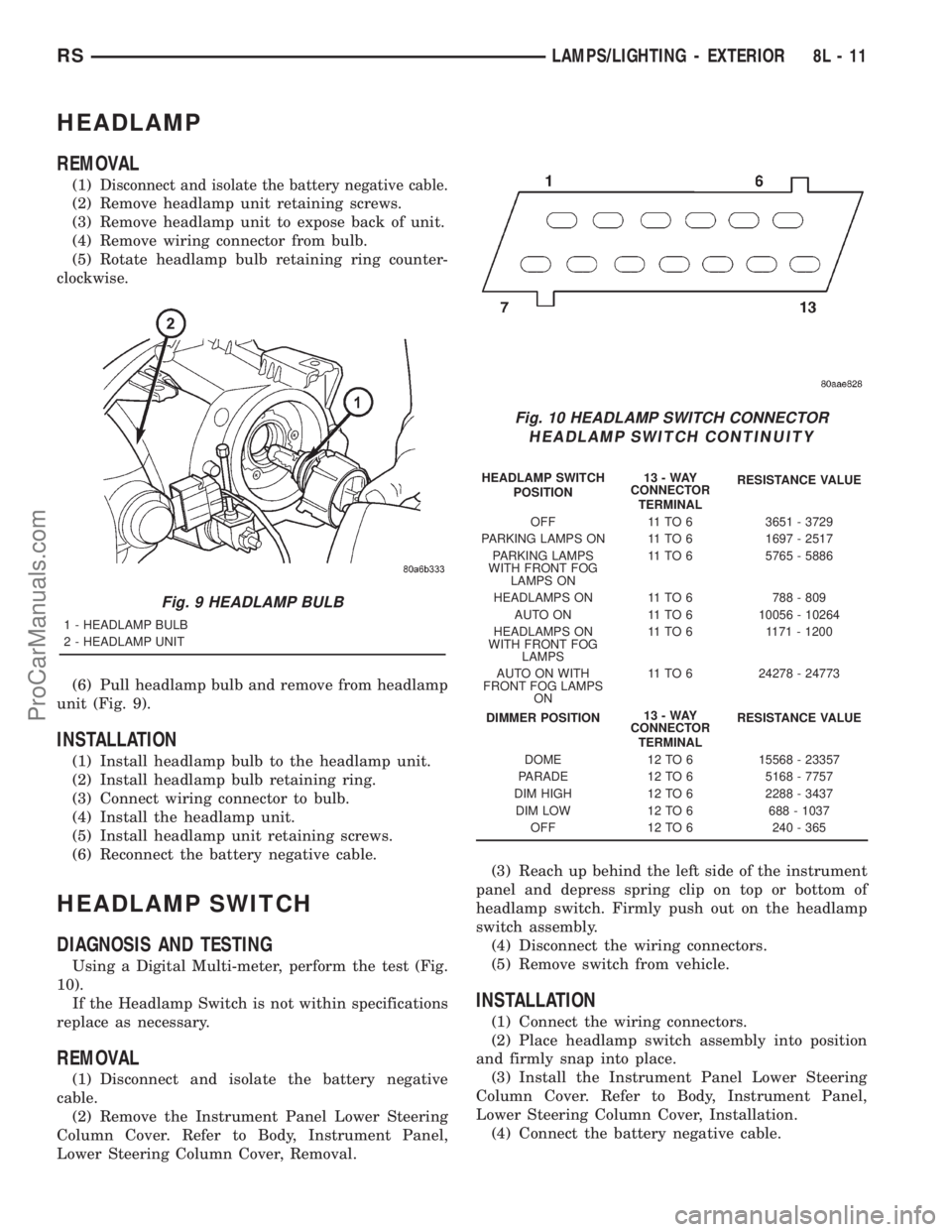
(6) Pull headlamp bulb and remove from headlamp
unit (Fig. 9).
INSTALLATION
(1) Install headlamp bulb to the headlamp unit.
(2) Install headlamp bulb retaining ring.
(3) Connect wiring connector to bulb.
(4) Install the headlamp unit.
(5) Install headlamp unit retaining screws.
(6) Reconnect the battery negative cable.
HEADLAMP SWITCH
DIAGNOSIS AND TESTING
Using a Digital Multi-meter, perform the test (Fig.
10).
If the Headlamp Switch is not within specifications
replace as necessary.
REMOVAL
(1) Disconnect and isolate the battery negative
cable.
(2) Remove the Instrument Panel Lower Steering
Column Cover. Refer to Body, Instrument Panel,
Lower Steering Column Cover, Removal.(3) Reach up behind the left side of the instrument
panel and depress spring clip on top or bottom of
headlamp switch. Firmly push out on the headlamp
switch assembly.
(4) Disconnect the wiring connectors.
(5) Remove switch from vehicle.
INSTALLATION
(1) Connect the wiring connectors.
(2) Place headlamp switch assembly into position
and firmly snap into place.
(3) Install the Instrument Panel Lower Steering
Column Cover. Refer to Body, Instrument Panel,
Lower Steering Column Cover, Installation.
(4) Connect the battery negative cable.
Fig. 9 HEADLAMP BULB
1 - HEADLAMP BULB
2 - HEADLAMP UNIT
Fig. 10 HEADLAMP SWITCH CONNECTOR
HEADLAMP SWITCH CONTINUITY
HEADLAMP SWITCH
POSITION13-WAY
CONNECTOR
TERMINALRESISTANCE VALUE
OFF 11 TO 6 3651 - 3729
PARKING LAMPS ON 11 TO 6 1697 - 2517
PARKING LAMPS
WITH FRONT FOG
LAMPS ON11 TO 6 5765 - 5886
HEADLAMPS ON 11 TO 6 788 - 809
AUTO ON 11 TO 6 10056 - 10264
HEADLAMPS ON
WITH FRONT FOG
LAMPS11 TO 6 1171 - 1200
AUTO ON WITH
FRONT FOG LAMPS
ON11 TO 6 24278 - 24773
DIMMER POSITION13-WAY
CONNECTOR
TERMINALRESISTANCE VALUE
DOME 12 TO 6 15568 - 23357
PARADE 12 TO 6 5168 - 7757
DIM HIGH 12 TO 6 2288 - 3437
DIM LOW 12 TO 6 688 - 1037
OFF 12 TO 6 240 - 365
RSLAMPS/LIGHTING - EXTERIOR8L-11
ProCarManuals.com
Page 491 of 2321
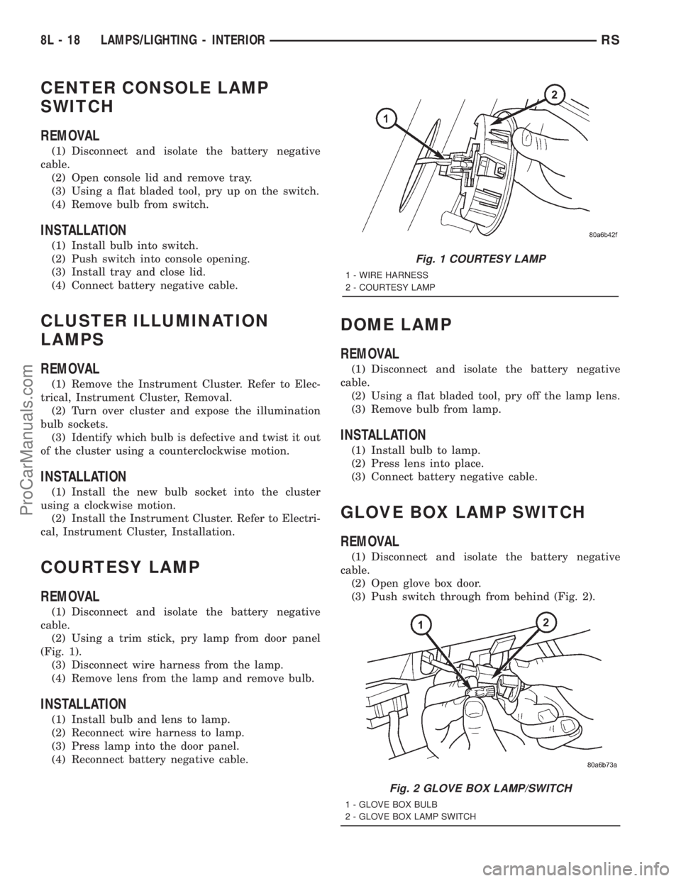
CENTER CONSOLE LAMP
SWITCH
REMOVAL
(1) Disconnect and isolate the battery negative
cable.
(2) Open console lid and remove tray.
(3) Using a flat bladed tool, pry up on the switch.
(4) Remove bulb from switch.
INSTALLATION
(1) Install bulb into switch.
(2) Push switch into console opening.
(3) Install tray and close lid.
(4) Connect battery negative cable.
CLUSTER ILLUMINATION
LAMPS
REMOVAL
(1) Remove the Instrument Cluster. Refer to Elec-
trical, Instrument Cluster, Removal.
(2) Turn over cluster and expose the illumination
bulb sockets.
(3) Identify which bulb is defective and twist it out
of the cluster using a counterclockwise motion.
INSTALLATION
(1) Install the new bulb socket into the cluster
using a clockwise motion.
(2) Install the Instrument Cluster. Refer to Electri-
cal, Instrument Cluster, Installation.
COURTESY LAMP
REMOVAL
(1) Disconnect and isolate the battery negative
cable.
(2) Using a trim stick, pry lamp from door panel
(Fig. 1).
(3) Disconnect wire harness from the lamp.
(4) Remove lens from the lamp and remove bulb.
INSTALLATION
(1) Install bulb and lens to lamp.
(2) Reconnect wire harness to lamp.
(3) Press lamp into the door panel.
(4) Reconnect battery negative cable.
DOME LAMP
REMOVAL
(1) Disconnect and isolate the battery negative
cable.
(2) Using a flat bladed tool, pry off the lamp lens.
(3) Remove bulb from lamp.
INSTALLATION
(1) Install bulb to lamp.
(2) Press lens into place.
(3) Connect battery negative cable.
GLOVE BOX LAMP SWITCH
REMOVAL
(1) Disconnect and isolate the battery negative
cable.
(2) Open glove box door.
(3) Push switch through from behind (Fig. 2).
Fig. 1 COURTESY LAMP
1 - WIRE HARNESS
2 - COURTESY LAMP
Fig. 2 GLOVE BOX LAMP/SWITCH
1 - GLOVE BOX BULB
2 - GLOVE BOX LAMP SWITCH
8L - 18 LAMPS/LIGHTING - INTERIORRS
ProCarManuals.com
Page 492 of 2321
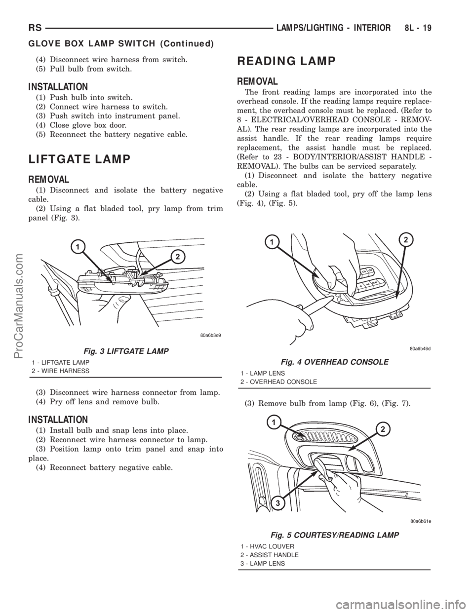
(4) Disconnect wire harness from switch.
(5) Pull bulb from switch.
INSTALLATION
(1) Push bulb into switch.
(2) Connect wire harness to switch.
(3) Push switch into instrument panel.
(4) Close glove box door.
(5) Reconnect the battery negative cable.
LIFTGATE LAMP
REMOVAL
(1) Disconnect and isolate the battery negative
cable.
(2) Using a flat bladed tool, pry lamp from trim
panel (Fig. 3).
(3) Disconnect wire harness connector from lamp.
(4) Pry off lens and remove bulb.
INSTALLATION
(1) Install bulb and snap lens into place.
(2) Reconnect wire harness connector to lamp.
(3) Position lamp onto trim panel and snap into
place.
(4) Reconnect battery negative cable.
READING LAMP
REMOVAL
The front reading lamps are incorporated into the
overhead console. If the reading lamps require replace-
ment, the overhead console must be replaced. (Refer to
8 - ELECTRICAL/OVERHEAD CONSOLE - REMOV-
AL). The rear reading lamps are incorporated into the
assist handle. If the rear reading lamps require
replacement, the assist handle must be replaced.
(Refer to 23 - BODY/INTERIOR/ASSIST HANDLE -
REMOVAL). The bulbs can be serviced separately.
(1) Disconnect and isolate the battery negative
cable.
(2) Using a flat bladed tool, pry off the lamp lens
(Fig. 4), (Fig. 5).
(3) Remove bulb from lamp (Fig. 6), (Fig. 7).
Fig. 3 LIFTGATE LAMP
1 - LIFTGATE LAMP
2 - WIRE HARNESSFig. 4 OVERHEAD CONSOLE
1 - LAMP LENS
2 - OVERHEAD CONSOLE
Fig. 5 COURTESY/READING LAMP
1 - HVAC LOUVER
2 - ASSIST HANDLE
3 - LAMP LENS
RSLAMPS/LIGHTING - INTERIOR8L-19
GLOVE BOX LAMP SWITCH (Continued)
ProCarManuals.com
Page 497 of 2321
HEADLAMP LEVELING MOTOR
DIAGNOSIS AND TESTING - HEADLAMP
LEVELING MOTOR
HEADLAMP LEVELING MOTOR DIAGNOSIS
CONDITION POSSIBLE CAUSES CORRECTION
ONE MOTOR DOES NOT
OPERATE1. Poor electrical connection at
motor1. Check for proper electrical
connection at motor
2. No voltage at motor 2. Repair no voltage condition.
Refer to Wiring Diagrams
3. No ground at motor 3. Repair no ground condition.
Refer to Wiring Diagrams
4. Defective motor 4. Replace leveling motor
BOTH MOTORS DO NOT
OPERATE1. No voltage at or from headlamp
leveling switch1. Repair no voltage condition.
Check for proper headlamp
leveling switch operation
2. No voltage at leveling motors 2. Repair no voltage condition.
Refer to Wiring Diagrams
3. No ground at leveling motors 3. Repair no ground condition.
Refer to Wiring Diagrams
4. Both motors defective 4. Replace both motors
REMOVAL
(1) Disconnect and isolate the battery negative
cable.
(2) Remove headlamp unit.
(3) Disconnect electrical connector from headlamp
leveling motor.
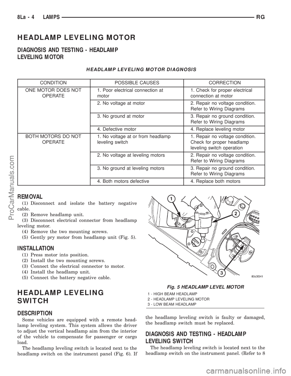
(4) Remove the two mounting screws.
(5) Gently pry motor from headlamp unit (Fig. 5).
INSTALLATION
(1) Press motor into position.
(2) Install the two mounting screws.
(3) Connect the electrical connector to motor.
(4) Install the headlamp unit.
(5) Connect the battery negative cable.
HEADLAMP LEVELING
SWITCH
DESCRIPTION
Some vehicles are equipped with a remote head-
lamp leveling system. This system allows the driver
to adjust the vertical headlamp aim from the interior
of the vehicle to compensate for passenger or cargo
load.
The headlamp leveling switch is located next to the
headlamp switch on the instrument panel (Fig. 6). Ifthe headlamp leveling switch is faulty or damaged,
the headlamp switch must be replaced.
DIAGNOSIS AND TESTING - HEADLAMP
LEVELING SWITCH
The headlamp leveling switch is located next to the
headlamp switch on the instrument panel. (Refer to 8
Fig. 5 HEADLAMP LEVEL MOTOR
1 - HIGH BEAM HEADLAMP
2 - HEADLAMP LEVELING MOTOR
3 - LOW BEAM HEADLAMP
8La - 4 LAMPSRG
ProCarManuals.com