2001 DODGE TOWN AND COUNTRY hvac
[x] Cancel search: hvacPage 1104 of 2321
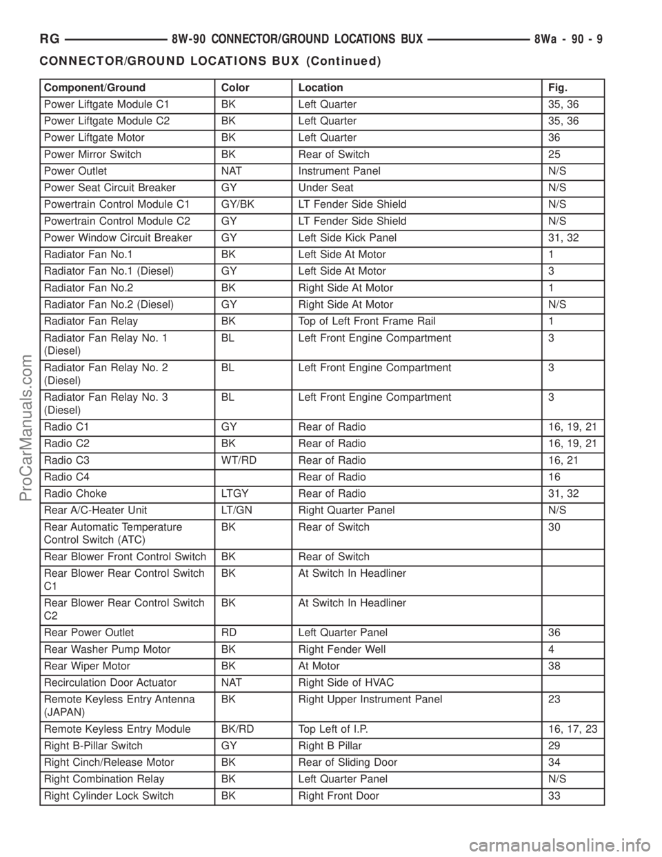
Component/Ground Color Location Fig.
Power Liftgate Module C1 BK Left Quarter 35, 36
Power Liftgate Module C2 BK Left Quarter 35, 36
Power Liftgate Motor BK Left Quarter 36
Power Mirror Switch BK Rear of Switch 25
Power Outlet NAT Instrument Panel N/S
Power Seat Circuit Breaker GY Under Seat N/S
Powertrain Control Module C1 GY/BK LT Fender Side Shield N/S
Powertrain Control Module C2 GY LT Fender Side Shield N/S
Power Window Circuit Breaker GY Left Side Kick Panel 31, 32
Radiator Fan No.1 BK Left Side At Motor 1
Radiator Fan No.1 (Diesel) GY Left Side At Motor 3
Radiator Fan No.2 BK Right Side At Motor 1
Radiator Fan No.2 (Diesel) GY Right Side At Motor N/S
Radiator Fan Relay BK Top of Left Front Frame Rail 1
Radiator Fan Relay No. 1
(Diesel)BL Left Front Engine Compartment 3
Radiator Fan Relay No. 2
(Diesel)BL Left Front Engine Compartment 3
Radiator Fan Relay No. 3
(Diesel)BL Left Front Engine Compartment 3
Radio C1 GY Rear of Radio 16, 19, 21
Radio C2 BK Rear of Radio 16, 19, 21
Radio C3 WT/RD Rear of Radio 16, 21
Radio C4 Rear of Radio 16
Radio Choke LTGY Rear of Radio 31, 32
Rear A/C-Heater Unit LT/GN Right Quarter Panel N/S
Rear Automatic Temperature
Control Switch (ATC)BK Rear of Switch 30
Rear Blower Front Control Switch BK Rear of Switch
Rear Blower Rear Control Switch
C1BK At Switch In Headliner
Rear Blower Rear Control Switch
C2BK At Switch In Headliner
Rear Power Outlet RD Left Quarter Panel 36
Rear Washer Pump Motor BK Right Fender Well 4
Rear Wiper Motor BK At Motor 38
Recirculation Door Actuator NAT Right Side of HVAC
Remote Keyless Entry Antenna
(JAPAN)BK Right Upper Instrument Panel 23
Remote Keyless Entry Module BK/RD Top Left of I.P. 16, 17, 23
Right B-Pillar Switch GY Right B Pillar 29
Right Cinch/Release Motor BK Rear of Sliding Door 34
Right Combination Relay BK Left Quarter Panel N/S
Right Cylinder Lock Switch BK Right Front Door 33
RG8W-90 CONNECTOR/GROUND LOCATIONS BUX8Wa-90-9
CONNECTOR/GROUND LOCATIONS BUX (Continued)
ProCarManuals.com
Page 2072 of 2321
(11) Install screws to attach accessary switch
panel to door trim.
(12) Install screw cover into switch panel.
(13) If equipped, install window crank.
(14) If equipped, install screws to attach trim
panel to door inside map pocket.
(15) If equipped, install screw to attach door pull
cup to inner door panel.
(16) If equipped, install screws to attach door
assist handle to inner door panel.
(17) Connect wire connector into courtesy lamp.
(18) Install lamp in door trim.
TRIM PANEL REFLECTOR
REMOVAL
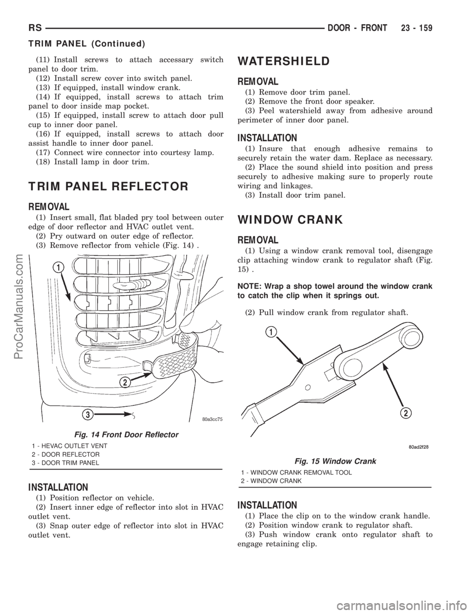
(1) Insert small, flat bladed pry tool between outer
edge of door reflector and HVAC outlet vent.
(2) Pry outward on outer edge of reflector.
(3) Remove reflector from vehicle (Fig. 14) .
INSTALLATION
(1) Position reflector on vehicle.
(2) Insert inner edge of reflector into slot in HVAC
outlet vent.
(3) Snap outer edge of reflector into slot in HVAC
outlet vent.
WATERSHIELD
REMOVAL
(1) Remove door trim panel.
(2) Remove the front door speaker.
(3) Peel watershield away from adhesive around
perimeter of inner door panel.
INSTALLATION
(1) Insure that enough adhesive remains to
securely retain the water dam. Replace as necessary.
(2) Place the sound shield into position and press
securely to adhesive making sure to properly route
wiring and linkages.
(3) Install door trim panel.
WINDOW CRANK
REMOVAL
(1) Using a window crank removal tool, disengage
clip attaching window crank to regulator shaft (Fig.
15) .
NOTE: Wrap a shop towel around the window crank
to catch the clip when it springs out.
(2) Pull window crank from regulator shaft.
INSTALLATION
(1) Place the clip on to the window crank handle.
(2) Position window crank to regulator shaft.
(3) Push window crank onto regulator shaft to
engage retaining clip.
Fig. 14 Front Door Reflector
1 - HEVAC OUTLET VENT
2 - DOOR REFLECTOR
3 - DOOR TRIM PANEL
Fig. 15 Window Crank
1 - WINDOW CRANK REMOVAL TOOL
2 - WINDOW CRANK
RSDOOR - FRONT23 - 159
TRIM PANEL (Continued)
ProCarManuals.com
Page 2117 of 2321
(17) Remove the two steering column shroud
retaining screws. Separate the shrouds and remove
from vehicle.
(18) Disconnect the steering column wiring. There
are seven connectors and then unclip the harness
from the column.
(19) Disconnect the ORC harness connector.
(20) Remove the four nuts retaining the steering
column and lower to the floor.
(21) Remove the four nuts attaching the instru-
ment panel to the brake pedal support bracket.
(22) Loosen the left side roll down bolt.
(23) Remove the left side A-pillar retaining bolts.
There are two 13 mm bolts and one 10 mm bolt.
(24) If equipped with a mechanical transmission
range indicator:
(a) Remove the indicator cable loop.
(b) Remove the clip holding gear shift cable end
to the gear selector adapter.
(c) Pull the cable end from gear selector.
(d) Disconnect the clip for the indicator cable
and guide tube from the shift cable bracket and
move out of the way.
(25) Remove the instrument panel top cover. Using
a trim stick or equivalent, gently pry up on the front
edge of the top cover, pull rearward and remove from
vehicle.
(26) Disconnect the right side wire connectors from
the HVAC behind the glove box area and the two
antenna connectors behind the glove box hinge.
(27) Remove the right end cover by pulling out-
board.
(28) Remove the right side A-pillar retaining bolts.
There are two 13 mm bolts and one 10 mm bolt.
(29) Loosen the right side roll down bolt.
(30) Disconnect the two front window defroster
grid wire connectors. One on each side of vehicle.
(31) Remove both the left and right power mirrors:
(a) Using a trim stick or equivalent, gently pry
out on mirror trim cover.
(b) Open door and remove the three torx retain-
ing screws.
(c) Disconnect the wire connector and remove
mirror from the vehicle.
(32) Feed power mirror wire harness inboard
through the A-pillar.
(33) Remove the bolts holding the instrument
panel frame to the dash panel below windshield
opening.
(34) With the help of an assistant remove the
instrument panel from vehicle. Lift the instrument
panel up off the HVAC so you won't damage the seal-
ing surface of the distribution duct.
If the instrument panel is being replaced, transfer
all parts to the new instrument panel assembly.INSTALLATION
(1) With the help of an assistant place the instru-
ment panel into vehicle on roll down bolts. As you
roll the instrument panel up, lift the instrument
panel up so the duct work does not bind or bend and
you can set it down on the HVAC housing to get the
proper seal at the distribution duct. Get one bolt
started in the dash panel.
(2) Install the bolts holding the instrument panel
frame to the dash panel below windshield opening.
(3) Feed power mirror wire harness outboard
through the A-pillar.
(4) Install both the left and right power mirrors:
(a) Connect the wire connector and install the
mirror onto the vehicle.
(b) Install the three torx retaining screws.
(c) Using a firm push, snap the mirror trim
cover into place.
(5) Connect the two front window defroster grid
wire connectors. One on each side of vehicle.
(6) Tighten the right side roll down bolt.
(7) Install the right side A-pillar retaining bolts.
There are two 13 mm bolts and one 10 mm bolt.
(8) Install the right end cover. Position over retain-
ing slots and firmly snap into place.
(9) Connect the right side wire connectors to the
HVAC behind the glove box area and the two
antenna connectors behind the glove box hinge.
(10) Install the instrument panel top cover. Slide
the front edge of the top cover toward dash panel,
and firmly snap down the rear edge of the to cover to
engage clips.
(11) If equipped with a mechanical transmission
range indicator:
(a) Connect the clip for the indicator cable and
guide tube to the shift cable bracket.
(b) Install the cable end to the gear selector.
(c) Install the clip holding the gear shift cable
end to the gear selector adapter.
(d) Install the indicator cable loop.
(12) Install the left side A-pillar retaining bolts.
There are two 13 mm bolts and one 10 mm bolt.
(13) Tighten the left side roll down bolt.
(14) Install the four nuts attaching the instrument
panel to the brake pedal support bracket.
(15) Install the four nuts retaining the steering
column and lower to the floor.
(16) Connect the ORC harness connector.
(17) Connect the steering column wiring. There
are seven connectors and then clip the harness to the
column.
(18) Connect the shrouds and install the two steer-
ing column shroud retaining screws.
(19) Install five screws to the left under column
instrument panel reinforcement brace.
23 - 204 INSTRUMENT PANELRS
INSTRUMENT PANEL ASSEMBLY (Continued)
ProCarManuals.com
Page 2118 of 2321
(20) Install the two screws to the hood release
handle.
(21) Connect the left side wiring:
(a) Brake switch.
(b) Main bulkhead connector.
(c) Five harness connectors.
(d) Driver airbag connector.
(22) Install one screw to the left side instrument
panel silencer.
(23) Clip the Data Link Connector (DLC) to the
instrument panel reinforcement.
(24) Install the eight screws to the plastic knee
blocker reinforcement.
(25) Install the four screws to the lower steering
column cover.
(26) Install the glove box:
(a) Install glove box into the vehicle. Line up the
hinges and firmly snap together.
(b) Push in on sides of glove box bin and raise
door.
(27) Install the both left and right side A-pillar
trim covers. Position trim cover over slots and firmly
snap into place.
(28) Install the two screws to each right and left
cowl trim covers.
(29) Connect the wire connectors to the Passenger
Airbag.
(30) Install the bolts holding the lower supports to
the floor pan.
(31) Install the bolts holding the lower supports to
the instrument panel frame.
(32) Install the lower console:
(a) Install lower console to vehicle.
(b) Connect the auxiliary power outlet.
(c) Install the six retaining screws.
(33) Connect the battery negative cable.
INSTRUMENT PANEL CENTER
BEZEL
REMOVAL
(1) Disconnect and isolate the battery negative
cable.
(2) Remove cup holder. Refer to Body, Instrument
Panel, Cup Holder, Removal.
(3) Insert the trim stick (special tool #C-4755) or
equivalent between access cover and center bezel.
(4) Carefully pry the access cover from the instru-
ment panel.
(5) Remove the cup holder track. Refer to Body,
Instrument Panel, Cup Holder, Removal.
(6) Using a trim stick or equivalent, gently pry out
on the edge of the instrument panel center bezel and
pull outward.(7) Disconnect the wire connectors to the accessory
switches and HVAC control.
(8) Remove the instrument panel center bezel from
the vehicle.
INSTALLATION
(1) Install the instrument panel center bezel from
the vehicle.
(2) Connect the wire connectors to the accessory
switches and HVAC control.
(3) Position the center bezel over the retaining
slots and firmly snap the instrument panel center
bezel into place.
(4) Install the cup holder track. Refer to Body,
Instrument Panel, Cup Holder, Installation.
(5) Position the center bezel over the retaining
slots and firmly snap into place.
(6) Install cup holder. Refer to Body, Instrument
Panel, Cup Holder, Installation.
(7) Connect the battery negative cable.
INSTRUMENT PANEL END
COVER
REMOVAL
(1) Open passenger side front door.
(2) Place fingers in end cover grille, and with a
firm outboard pulling motion, disengage clips holding
end cover to instrument panel.
INSTALLATION
(1) Position end cover over retaining slots and
firmly snap into place.
(2) Close passenger side front door.
INSTRUMENT PANEL TOP
COVER
REMOVAL
(1) Remove A-pillar trim. Using a trim stick (spe-
cial tool #C-4755) or equivalent, gently pry out and
remove.
(2) Using a trim stick, disengage clips holding rear
edge of top cover to instrument panel.
NOTE: The Instrument Panel Top Cover may be
hard to unsnap from the instrument panel. Be sure
not to mar, scuff, or damage the instrument panel
pad.
(3) Pull top cover rearward to disengage hooks
holding front of top cover to instrument panel.
(4) Remove top cover from vehicle.
RSINSTRUMENT PANEL23 - 205
INSTRUMENT PANEL ASSEMBLY (Continued)
ProCarManuals.com
Page 2121 of 2321
INTERIOR
TABLE OF CONTENTS
page page
A-PILLAR LOWER EXTENSION TRIM
REMOVAL.............................209
INSTALLATION..........................209
A-PILLAR TRIM
REMOVAL.............................209
INSTALLATION..........................209
ASSIST HANDLE
REMOVAL.............................209
INSTALLATION..........................209
B-PILLAR LOWER TRIM
REMOVAL.............................209
INSTALLATION..........................210
B-PILLAR UPPER TRIM
REMOVAL.............................210
INSTALLATION..........................210
CARPETS AND FLOOR MATS
REMOVAL.............................211
INSTALLATION..........................211
COWL TRIM
REMOVAL.............................212
INSTALLATION..........................212
C-PILLAR TRIM
REMOVAL.............................212
INSTALLATION..........................212
DOOR SILL TRIM PLATE
REMOVAL.............................212
INSTALLATION..........................212
HEADLINER
REMOVAL.............................213
INSTALLATION..........................213
JACK STORAGE COVER
REMOVAL.............................213
INSTALLATION..........................214
LEFT D-PILLAR TRIM PANEL
REMOVAL.............................214
INSTALLATION..........................214
LIFTGATE SCUFF PLATE
REMOVAL.............................214INSTALLATION..........................214
QUARTER TRIM BOLSTER
REMOVAL.............................214
INSTALLATION..........................214
RIGHT QUARTER TRIM PANEL
REMOVAL.............................215
INSTALLATION..........................215
LEFT QUARTER TRIM PANEL
REMOVAL.............................215
INSTALLATION..........................215
REAR HEADER TRIM
REMOVAL.............................216
INSTALLATION..........................216
REAR HVAC LOUVER
REMOVAL.............................216
INSTALLATION..........................216
REAR VIEW MIRROR
REMOVAL.............................217
INSTALLATION..........................217
RIGHT D-PILLAR TRIM PANEL
REMOVAL.............................217
INSTALLATION..........................217
SLIDING DOOR SILL PLATE
REMOVAL.............................218
INSTALLATION..........................218
SUN VISOR
REMOVAL.............................218
INSTALLATION..........................218
SUN VISOR SUPPORT
REMOVAL.............................219
INSTALLATION..........................219
FLOOR CONSOLE TRAY
REMOVAL.............................219
INSTALLATION..........................219
FLOOR CONSOLE TRAY - BRACKET
ASSEMBLY
REMOVAL.............................219
INSTALLATION..........................219
23 - 208 INTERIORRS
ProCarManuals.com
Page 2129 of 2321
(4) Pass front seat belt through slot in quarter
trim panel on three door vehicle.
(5) Connect wire connector into accessory power
outlet, if equipped.
(6) Align locating pins on backside of trim panel to
mating holes in inner panels.
(7) Position quarter trim panel on inner quarter
panel.
(8) Install screws attaching top of trim panel to
inner sheet metal between B-pillar and C-pillar on
three door vehicle.
(9) Install screws attaching rear edge of quarter
trim to attaching bracket or inner quarter panel.
(10) Install screws attaching quarter trim to inner
quarter panel in bolster area.
(11) Install screws attaching quarter trim to inner
quarter panel in B-pillar area on three door vehicle.
(12) Install left front seat belt opening bezel into
quarter trim on three door vehicle.
(13) Install second row seat belts anchor on long
wheel base vehicle. Tighten all seat belt bolts to 39
N´m (28 in. lbs.) torque.
(14) Install first row seat belt anchor.
(15) Install left D-pillar trim panel.
(16) Install C-pillar trim panel.
(17) Install upper left B-pillar trim on three door
vehicle.
(18) Install left quarter trim bolster.
(19)
Install front door sill plate on three door vehicle.
(20) Install sliding door sill plate on four door
vehicle.
(21) Install second row seat, if equipped.
(22) Install first row seat.
(23) Connect the battery negative cable.
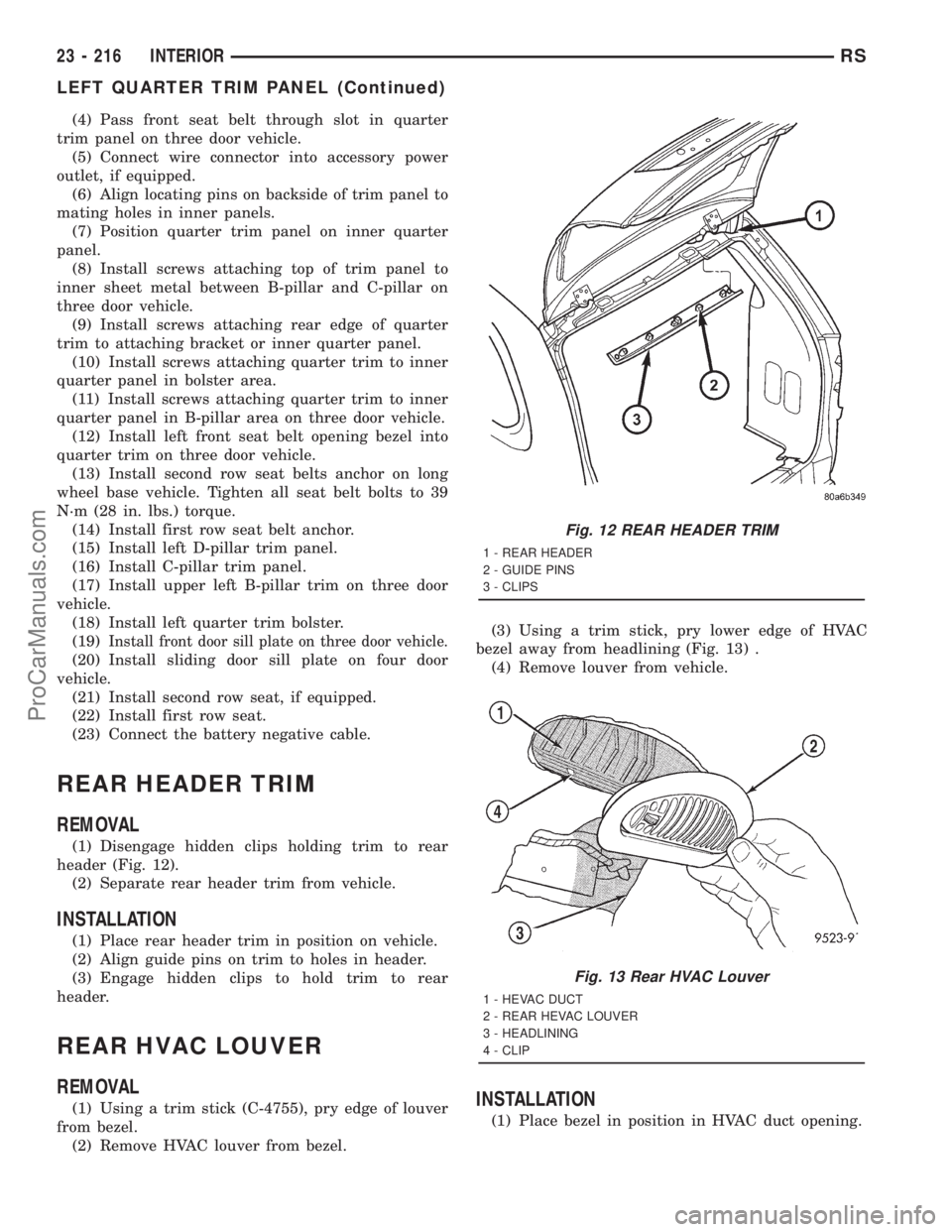
REAR HEADER TRIM
REMOVAL
(1) Disengage hidden clips holding trim to rear
header (Fig. 12).
(2) Separate rear header trim from vehicle.
INSTALLATION
(1) Place rear header trim in position on vehicle.
(2) Align guide pins on trim to holes in header.
(3) Engage hidden clips to hold trim to rear
header.
REAR HVAC LOUVER
REMOVAL
(1) Using a trim stick (C-4755), pry edge of louver
from bezel.
(2) Remove HVAC louver from bezel.(3) Using a trim stick, pry lower edge of HVAC
bezel away from headlining (Fig. 13) .
(4) Remove louver from vehicle.INSTALLATION
(1) Place bezel in position in HVAC duct opening.
Fig. 12 REAR HEADER TRIM
1 - REAR HEADER
2 - GUIDE PINS
3 - CLIPS
Fig. 13 Rear HVAC Louver
1 - HEVAC DUCT
2 - REAR HEVAC LOUVER
3 - HEADLINING
4 - CLIP
23 - 216 INTERIORRS
LEFT QUARTER TRIM PANEL (Continued)
ProCarManuals.com
Page 2130 of 2321
(2) Push inward on bezel until clips snap in place.
Verify that all four clips have been engaged to the
bezel and that the bezel is flush to the headlining
(3) Position HVAC louver to bezel.
(4) Snap both ends of the louver into HVAC bezel.
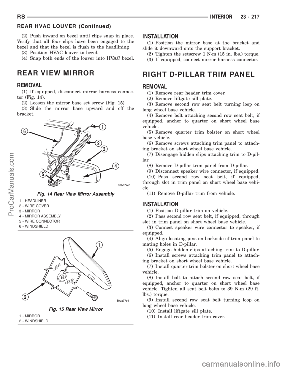
REAR VIEW MIRROR
REMOVAL
(1) If equipped, disconnect mirror harness connec-
tor (Fig. 14).
(2) Loosen the mirror base set screw (Fig. 15).
(3) Slide the mirror base upward and off the
bracket.
INSTALLATION
(1) Position the mirror base at the bracket and
slide it downward onto the support bracket.
(2) Tighten the setscrew 1 N´m (15 in. lbs.) torque.
(3) If equipped, connect mirror harness connector.
RIGHT D-PILLAR TRIM PANEL
REMOVAL
(1) Remove rear header trim cover.
(2) Remove liftgate sill plate.
(3) Remove second row seat belt turning loop on
long wheel base vehicle.
(4) Remove bolt attaching second row seat belt, if
equipped, anchor to quarter on short wheel base
vehicle.
(5) Remove quarter trim bolster on short wheel
base vehicle.
(6) Remove screws attaching trim panel to attach-
ing bracket on short wheel base vehicle.
(7) Disengage hidden clips attaching trim to D-pil-
lar.
(8) Remove D-pillar trim panel from D-pillar.
(9) Disconnect speaker wire connector, if equipped.
(10) Pass second row seat belt, if equipped,
through slot in trim panel on short wheel base vehi-
cle.
(11) Remove D-pillar trim from vehicle.
INSTALLATION
(1) Position D-pillar trim on vehicle.
(2) Pass second row seat belt, if equipped, through
slot in trim panel on short wheel base vehicle.
(3) Connect speaker wire connector to speaker, if
equipped.
(4) Align locating pins on backside of trim panel to
mating holes in D-pillar.
(5) Engage hidden clips attaching trim to D-pillar.
(6) Install screws attaching trim panel to attach-
ing bracket on short wheel base vehicle.
(7) Install quarter trim bolster on short wheel base
vehicle.
(8) Install bolt to attach second row seat belt, if
equipped, anchor to quarter on short wheel base
vehicle. Tighten all seat belt bolts to 39 N´m (29 ft.
lbs.) torque.
(9) Install second row seat belt turning loop on
long wheel base vehicle.
(10) Install liftgate sill plate.
(11) Install rear header trim cover.
Fig. 14 Rear View Mirror Assembly
1 - HEADLINER
2 - WIRE COVER
3 - MIRROR
4 - MIRROR ASSEMBLY
5 - WIRE CONNECTOR
6 - WINDSHIELD
Fig. 15 Rear View Mirror
1 - MIRROR
2 - WINDSHIELD
RSINTERIOR23 - 217
REAR HVAC LOUVER (Continued)
ProCarManuals.com
Page 2166 of 2321
²Rear window defogger on/off switch. A graphic
symbol shows when the defroster is on.
²An air conditioning button that allows the com-
pressor to be turned off. A Snowflake symbol is illu-
minated when air conditioning is on, whether under
manual or automatic control.
²Rotary knob for front fan speed selection can
override the automatic controls. LEDs surrounding
the knob show the current setting.
²Rotary knob for control of the Rear system.
²A rotary knob for mode control can override the
automatic controls. LEDs surrounding the knob show
the current setting.
²Computer logic remembers the settings of the
controls when the ignition is turned off and retains
those settings after a restart. If the system is off
when the ignition is turned of, it will be off when the
engine is restarted, etc.
²Computer logic provides variable air recircula-
tion under high temperature and humidity condi-
tions. Because recirculation is generally accompanied
by increased fan noise, the proportion of recirculated
to outside air gradually approaches full recirculation
over a broad temperature range.
²A graphic symbol of the windshield that illumi-
nates when the windshield wiper deicer is active.
REAR CONTROL PANEL
A rear control panel centrally mounted on the
headliner includes a vacuum-flourescent digital dis-
play, a rocker control for temperature and rotary con-
trols for adjustment of mode and fan speed control of
the rear unit by intermediate seat passengers.
OPERATION - DUAL ZONE
²The mode control knob enables continously vari-
able proportioning of air flow between modes but has
detents adjacent to each icon.
²The blower control provides five separate speeds.
²When the fan is off, the HVAC computer closes
the recirculation door to prevent outside air from
entering the passenger compartment.
²Interior air may be recirculated to speed up
heating or cooling in all modes exccept defrost and
mix by pressing the Recirculate button on the control
panel.
²To reduce humidity for rapid defogging the A/C
compressor runs automatically in modes from ªmix'
to full defrost when outside temperautres are above
freezing.
²Air conditioning is available in any mode by
pressing the snowflake, A/C on/off, button.
OPERATION - MANUAL THREE ZONE
FRONT CONTROL PANEL
²Primary control of the rear compartment unit is
on the instrument panel. This control allows the
driver to set the rear compartment fan speed, to turn
the rear unit off, or to give control to the intermedi-
ate seat occupants by switching to the REAR posi-
tion. When the rear unit is controlled from the
instrument panel, rear air temperature is based on
the driver-side temperature control position, and the
mode (floor or overhead air) is based on the front
control's mode position.
²The mode control knob enables continously vari-
able proportioning of air flow between modes but has
detents adjacent to each icon.
²The blower control provides five separate speeds
and Off. When the fan is off, the HVAC computer
closes the recirculation door to prevent outside air
from entering the passenger compartment.
²Interior air may be recirculated to speed up
heating or cooling in all modes exccept defrost and
mix by pressing the Recirculate button on the control
panel.
²To reduce humidity for rapid defogging the A/C
compressor runs automatically in modes from ªmix'
to full defrost when outside temperautres are above
freezing.
²Air conditioning is available in any mode by
pressing the snowflake, A/C on/off, button.
REAR CONTROL PANEL
With the rear control active, temperature selection
dictates indirectly the mode (floor or overhead air) of
the rear unit: a low temperature setting directs flow
to the overhead outlets and a high temperature set-
ting to the floor.
OPERATION - THREE ZONE ATC
Comfort temperature or perceived temperature is
affected by air flow, sun impinging on exposed skin,
etc. The air temperature may be higher or lower than
the comfort temperature. Three infrared sensors, two
in the instrument panel center stack, and one in the
overhead-mounted rear control panel, independently
measure the temperature of the driver, front passen-
ger, and rear compartment occupants to determine
their comfort level relative to the selected comfort
temperature. The HVAC computer in the control
module adjusts the air flow rate and temperature to
maintain the customer-perceived comfort tempera-
ture. The air temperature in the passenger compart-
ment at any time may be slightly higher or lower
than the comfort temperature. For instance, on
sunny summer days the air flow will probably be
cooler than the comfort temperature; on cold or
RSHEATING & AIR CONDITIONING24-3
HEATING & AIR CONDITIONING (Continued)
ProCarManuals.com