2001 DODGE TOWN AND COUNTRY hvac
[x] Cancel search: hvacPage 240 of 2321
CAUTION: A seal on the rear of the master cylinder
is used to create the seal for holding vacuum in the
power brake vacuum booster. The vacuum seal on
the master cylinder MUST be replaced whenever the
master cylinder is removed from the power brake
vacuum booster.
(12) Remove vacuum seal located on the mounting
flange of the master cylinder. The vacuum seal is
removed from master cylinder bycarefullypulling it
off the rear of master cylinder.Do not attempt to
pry the seal off the master cylinder by inserting
a sharp tool between seal and master cylinder
casting.
INSTALLATION
CAUTION: Different types of master cylinders are
used on this vehicle depending on brake options. If
a new master cylinder is being installed, be sure it
is the correct master cylinder for the type of brake
system the vehicle is equipped with.
CAUTION: When replacing the master cylinder on a
vehicle, a NEW vacuum seal MUST be installed on
the master cylinder.
(1) Install a NEW vacuum seal on master cylinder
making sure seal fits squarely in groove of master
cylinder casting.
(2) Position master cylinder on studs of power
brake booster, aligning booster push rod with master
cylinder piston.
(3) Install the two master cylinder mounting nuts
(Fig. 2). Tighten both mounting nuts to a torque of
25 N´m (225 in. lbs.).
CAUTION: When tightening the primary and sec-
ondary brake tube nuts at master cylinder, be sure
brake tubes do not contact any other components
within the vehicle and that there is slack in the flex-
ible sections of the tubes. This is required due to
the movement between the ABS ICU and the master
cylinder while the vehicle is in motion.
(4) Connect primary and secondary brake tubes to
master cylinder primary and secondary ports (Fig. 2).
Brake tubes must be held securely when tightened to
control orientation of flex section. Tighten tube nuts
to a torque of 17 N´m (145 in. lbs.).
(5) Install wiring harness connector to brake fluid
level switch mounted in brake fluid reservoir (Fig. 1).
(6) Install battery, clamp and nut.
(7) Install battery shield.
(8) Connect positive battery terminal.
(9) Connect negative battery terminal.(10) Fill master cylinder with clean, fresh Mopart
Brake Fluid or equivalent.
(11) Road test vehicle to ensure proper operation of
brakes.
PEDAL TORQUE SHAFT
REMOVAL
(1) Remove the instrument panel. (Refer to 23 -
BODY/INSTRUMENT PANEL/INSTRUMENT
PANEL ASSEMBLY - REMOVAL)
(2) Remove the HVAC housing. (Refer to 24 -
HEATING & AIR CONDITIONING/DISTRIBUTION/
HVAC HOUSING - REMOVAL)
(3) Remove the retaining clip at the torque shaft
end of the brake pedal-to-torque shaft link. Remove
the link from the torque shaft. Discard the retaining
clip. It is not to be reused. Replace with a new clip
when reassembled.
(4) Locate the booster input rod-to-brake pedal
torque shaft connection and remove the retaining clip
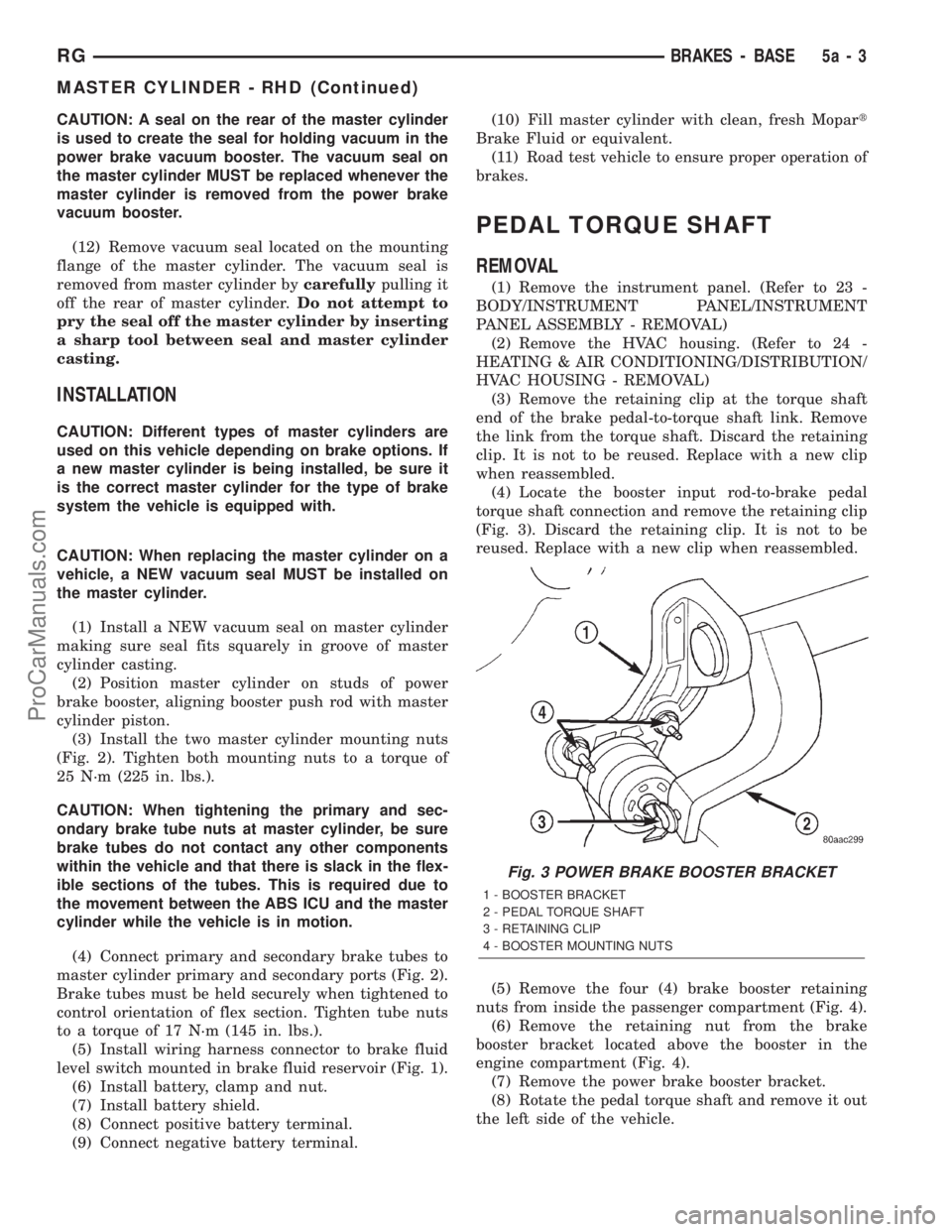
(Fig. 3). Discard the retaining clip. It is not to be
reused. Replace with a new clip when reassembled.
(5) Remove the four (4) brake booster retaining
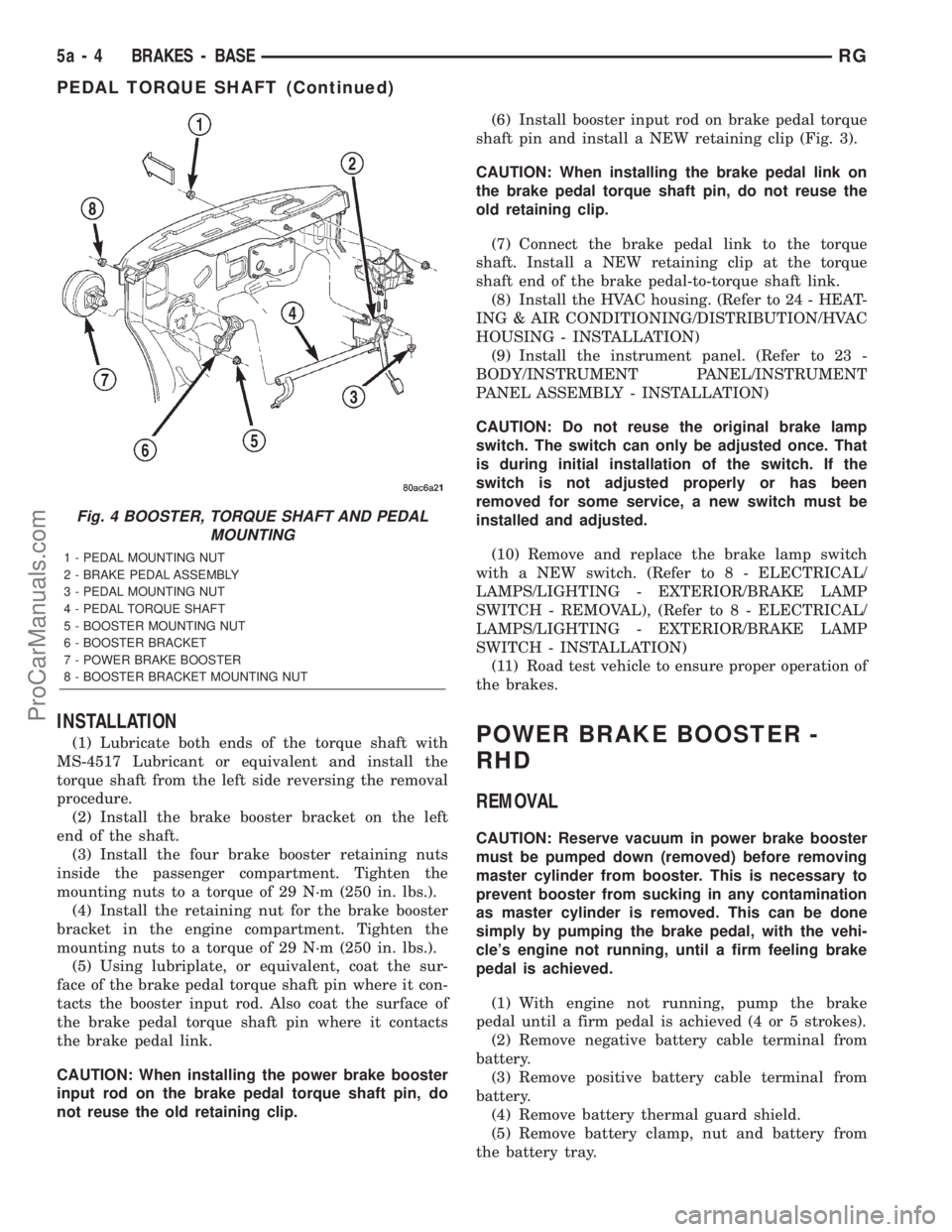
nuts from inside the passenger compartment (Fig. 4).
(6) Remove the retaining nut from the brake
booster bracket located above the booster in the
engine compartment (Fig. 4).
(7) Remove the power brake booster bracket.
(8) Rotate the pedal torque shaft and remove it out
the left side of the vehicle.
Fig. 3 POWER BRAKE BOOSTER BRACKET
1 - BOOSTER BRACKET
2 - PEDAL TORQUE SHAFT
3 - RETAINING CLIP
4 - BOOSTER MOUNTING NUTS
RGBRAKES - BASE5a-3
MASTER CYLINDER - RHD (Continued)
ProCarManuals.com
Page 241 of 2321
INSTALLATION
(1) Lubricate both ends of the torque shaft with
MS-4517 Lubricant or equivalent and install the
torque shaft from the left side reversing the removal
procedure.
(2) Install the brake booster bracket on the left
end of the shaft.
(3) Install the four brake booster retaining nuts
inside the passenger compartment. Tighten the
mounting nuts to a torque of 29 N´m (250 in. lbs.).
(4) Install the retaining nut for the brake booster
bracket in the engine compartment. Tighten the
mounting nuts to a torque of 29 N´m (250 in. lbs.).
(5) Using lubriplate, or equivalent, coat the sur-
face of the brake pedal torque shaft pin where it con-
tacts the booster input rod. Also coat the surface of
the brake pedal torque shaft pin where it contacts
the brake pedal link.
CAUTION: When installing the power brake booster
input rod on the brake pedal torque shaft pin, do
not reuse the old retaining clip.(6) Install booster input rod on brake pedal torque
shaft pin and install a NEW retaining clip (Fig. 3).
CAUTION: When installing the brake pedal link on
the brake pedal torque shaft pin, do not reuse the
old retaining clip.
(7) Connect the brake pedal link to the torque
shaft. Install a NEW retaining clip at the torque
shaft end of the brake pedal-to-torque shaft link.
(8) Install the HVAC housing. (Refer to 24 - HEAT-
ING & AIR CONDITIONING/DISTRIBUTION/HVAC
HOUSING - INSTALLATION)
(9) Install the instrument panel. (Refer to 23 -
BODY/INSTRUMENT PANEL/INSTRUMENT
PANEL ASSEMBLY - INSTALLATION)
CAUTION: Do not reuse the original brake lamp
switch. The switch can only be adjusted once. That
is during initial installation of the switch. If the
switch is not adjusted properly or has been
removed for some service, a new switch must be
installed and adjusted.
(10) Remove and replace the brake lamp switch
with a NEW switch. (Refer to 8 - ELECTRICAL/
LAMPS/LIGHTING - EXTERIOR/BRAKE LAMP
SWITCH - REMOVAL), (Refer to 8 - ELECTRICAL/
LAMPS/LIGHTING - EXTERIOR/BRAKE LAMP
SWITCH - INSTALLATION)
(11) Road test vehicle to ensure proper operation of
the brakes.POWER BRAKE BOOSTER -
RHD
REMOVAL
CAUTION: Reserve vacuum in power brake booster
must be pumped down (removed) before removing
master cylinder from booster. This is necessary to
prevent booster from sucking in any contamination
as master cylinder is removed. This can be done
simply by pumping the brake pedal, with the vehi-
cle's engine not running, until a firm feeling brake
pedal is achieved.
(1) With engine not running, pump the brake
pedal until a firm pedal is achieved (4 or 5 strokes).
(2) Remove negative battery cable terminal from
battery.
(3) Remove positive battery cable terminal from
battery.
(4) Remove battery thermal guard shield.
(5) Remove battery clamp, nut and battery from
the battery tray.
Fig. 4 BOOSTER, TORQUE SHAFT AND PEDAL
MOUNTING
1 - PEDAL MOUNTING NUT
2 - BRAKE PEDAL ASSEMBLY
3 - PEDAL MOUNTING NUT
4 - PEDAL TORQUE SHAFT
5 - BOOSTER MOUNTING NUT
6 - BOOSTER BRACKET
7 - POWER BRAKE BOOSTER
8 - BOOSTER BRACKET MOUNTING NUT
5a - 4 BRAKES - BASERG
PEDAL TORQUE SHAFT (Continued)
ProCarManuals.com
Page 341 of 2321
TEST 1
Test 1 determines of the antenna mast is insulated
from the base. Proceed as follows:
(1) Unplug the antenna coaxial cable from the
radio chassis and isolate. Remove the antenna mast.
(2) Connect an ohmmeter test lead to the inside
center of the antenna base. Connect the other test
lead to a metallic portion on the outside of the
antenna base. Check for continuity.
(3) There should be no continuity. If continuity is
found, replace the faulty or damaged antenna base
and cable assembly.
TEST 2
Test 2 checks the antenna for an open circuit as
follows:
(1) Unplug the antenna coaxial cable connector
from the radio chassis. Remove the antenna mast.
The painted mast prevents measurement directly
through the mast.
(2) Connect an ohmmeter test lead to the inside
center of the antenna base. Connect the other test
lead to the center pin of the antenna coaxial cable
connector.
(3) Continuity should exist (the ohmmeter should
only register a fraction of an ohm). High or infinite
resistance indicates damage to the base and cable
assembly. Replace the faulty base and cable if
required.
TEST 3
Test 3 checks the condition of the ground between
the antenna base and the vehicle body as follows:
(1) Connect one ohmmeter test lead to the fender
on an exposed metal area (paint and e-coat must be
penetrated to obtain continuity). Connect the other
test lead to the outer crimp on the antenna coaxial
cable connector.
(2) The resistance should be less than (1) ohm.
(3) If the resistance is more than (1) ohm, clean
and/or tighten the antenna base to the fender mount-
ing hardware.
REMOVAL
ANTENNA MAST AND CABLE LEAD
(1) Remove glove box from instrument panel,
(Refer to 23 - BODY/INSTRUMENT PANEL/GLOVE
BOX - REMOVAL).
(2) Disconnect antenna cable connector from exten-
sion cable (Fig. 2).
(3) Remove right kick trim panel.
(4) Disengage rubber grommet insulator from door
hinge pillar.
(5) Pull antenna cable through hinge pillar into
opening between door hinges.(6) Hoist and support vehicle on safety stands.
(7) Remove front wheel.
(8) Remove front wheelhouse splash shield. (Refer
to 23 - BODY/EXTERIOR/LF WHEELHOUSE
SPLASH SHIELD - REMOVAL).
(9) Remove antenna mast from antenna base (Fig.
3).
(10) Remove plastic cap from the cap nut. Using
cap nut tool, remove cap nut holding antenna base to
front fender (Fig. 4).
(11) Remove antenna base from under front fender.
ANTENNA EXTENSION CABLE
(1) Remove glove box. (Refer to 23 - BODY/IN-
STRUMENT PANEL/GLOVE BOX - REMOVAL).
(2) Disconnect extension cable end from antenna
cable end.
(3) Disconnect cable hanger clip from HVAC unit.
(4) Remove radio as necessary to gain access to
extension cable. (Refer to 8 - ELECTRICAL/AUDIO/
RADIO - REMOVAL).
(5) Disconnect extension cable from back of radio.
(6) Remove extension cable from vehicle.
INSTALLATION
ANTENNA MAST AND CABLE LEAD
(1) Install antenna base to underside of front
fender.
(2) Install cap nut holding antenna base to front
fender.
(3) Install plastic cap to the cap nut.
(4) Install antenna mast to antenna base.
(5) Install front wheelhouse splash shield.
(6) Install front wheel.
(7) Lower vehicle.
(8) Push antenna cable through opening in hinge
pillar.
(9) Insert rubber grommet into door hinge pillar.
(10) Install kick panel.
(11) Connect antenna cable connector to extension
cable.
(12) Install glove box to instrument panel.
ANTENNA EXTENSION CABLE
(1) Install extension cable to vehicle.
(2) Connect extension cable to back of radio.
(3) Install radio. (Refer to 8 - ELECTRICAL/AU-
DIO/RADIO - INSTALLATION).
(4) Connect cable hanger clip to HVAC unit.
(5) Connect extension cable end to antenna cable
end.
(6) Install glove box. (Refer to 23 - BODY/IN-
STRUMENT PANEL/GLOVE BOX - INSTALLA-
TION).
8A - 4 AUDIORS
ANTENNA BODY & CABLE (Continued)
ProCarManuals.com
Page 431 of 2321

OPERATION
The Rear Window Defogger (Fig. 1) system consists
of two vertical bus bars linked by a series of grid
lines on the inside surface of the rear window. The
electrical circuit consists of the rear defogger switch
in the HVAC control assembly and a relay with timer
switch to turn OFF the system after ten minutes.
The main feed circuit is protected by fuse 13 (40
amp) in the Power Distribution Center (PDC) which
is integrated as a unit call Integrated Power Module
(IPM). The rear defogger switch and relay also acti-
vates the heated power side view mirrors and heated
windshield wiper de-icer. The heated windshield
wiper de-icer is powered by the RUN/ACC relay in
the IPM and feed thru fuse #11 (20 amp) in the PDC.
The heated mirror circuit is protected by a non-servi-
cable Positive Temperature Coefficient (PTC) located
inside the PDC. The heated windshield wiper de-icer
circuit is protected by fuse 11 (20 amp) in the PDC.
The Heated Windshield Wiper Deicer is also acti-
vated when the DEFROST mode is selected on the
HVAC. In the DEFROST mode the rear defogger
relay/timer is bypassed, the heated windshield wiper
de-icer will stay ON until the another mode is
selected. For circuit information and component loca-
tion refer to appropriate section for Wiring Diagrams.
CAUTION:
Since grid lines can be damaged or scraped off
with sharp instruments, care should be taken in
cleaning the glass or removing foreign materials,
decals or stickers. Normal glass cleaning solvents
or hot water used with rags or toweling is recom-
mended.
DEFOGGER RELAY
DESCRIPTION
There is no heated glass relay it is integrated into
the (E.B.L) relay that is located in the IPM in the
engine compartment.
REAR WINDOW DEFOGGER
GRID
STANDARD PROCEDURE - GRID LINE
REPAIR-REAR
For Grid repair procedure for the rear window
defogger (Refer to 8 - ELECTRICAL/HEATED
GLASS/WINDSHIELD GRID - STANDARD PROCE-
DURE).
REAR WINDOW DEFOGGER
SWITCH
DESCRIPTION
The rear window defogger switch is integrated into
the HVAC control panel assembly (Fig. 3)
OPERATION
A LED indicator will illuminate when the switch is
activated. The switch energizes the HVAC control
assembly when it requests the Front Control Module
(FCM) to activate the rear window defogger relay.
The relay controls the current to flow to the grids of
the rear window defogger, heated power side view
mirrors and the heated windshield wiper de-icer. The
defogger relay will be on for approximately 10 min-
utes or until the control switch or ignition is turned
off.
Fig. 3 HVAC CONTROL PANEL
1 - Trim Bezel
2 - ACT Sensor
3 - A/C Request Switch
4 - Rear Window Defogger/Heated Mirrors Switch Combo
5 - Front Window Defroster Mode Selector
8G - 2 HEATED GLASSRS
HEATED GLASS (Continued)
ProCarManuals.com
Page 432 of 2321
WINDSHIELD GRID
DIAGNOSIS AND TESTING - SYSTEM TEST
Electrically heated rear window defogger or the
heated windshield wiper deicer operation can be
checked on the vehicle in the following manner:
(1) Turn the ignition switch to the ON position.
(2) Using a ammeter on the battery, turn the rear
defogger control switch to the ON position, a distinct
increase in amperage draw should be noted.
(3) The rear window defogger or the heated wind-
shield wiper deicer operation can be checked by feel-
ing the glass. A distinct difference in temperature
between the grid lines and adjacent clear glass can
be detected in 3 to 4 minutes of operation.
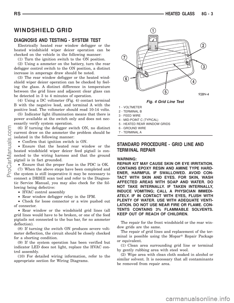
(4) Using a DC voltmeter (Fig. 4) contact terminal
B with the negative lead, and terminal A with the
positive lead. The voltmeter should read 10-14 volts.
(5) Indicator light illumination means that there is
power available at the switch only and does not nec-
essarily verify system operation.
(6) If turning the defogger switch ON, no distinct
current draw on the ammeter the problem should be
isolated in the following manner:
²Confirm that ignition switch is ON.
²Ensure that the heated rear window or the
heated windshield wiper deicer feed pigtail is con-
nected to the wiring harness and that the ground
pigtail is in fact grounded.
²Ensure that the proper fuse in the PDC is OK.
(7) When the above steps have been completed and
the system is still inoperative it may be necessary to
connect a DRBIII scan tool and refer to the Diagnos-
tic Service Manual, you may also check for the fol-
lowing being defective:
²HVAC control assembly
²Rear window defogger relay in the IPM.
²Check for loose connector or a wire pushed out
of connector.
²Rear window or the windshield grid lines (all
grid lines would have to be broken, or one of the feed
pigtails not connected to the bus bar, for no ammeter
deflection).
(8) If turning the switch ON produces severe volt-
meter deflection, the circuit should be closely checked
for a shorting condition.
(9) If the system operation has been verified but
indicator LED does not light, replace the HVAC con-
trol assembly.
(10) For detailed wiring information, refer to the
appropriate section for Wiring Diagrams.
STANDARD PROCEDURE - GRID LINE AND
TERMINAL REPAIR
WARNING:
REPAIR KIT MAY CAUSE SKIN OR EYE IRRITATION.
CONTAINS EPOXY RESIN AND AMINE TYPE HARD-
ENER, HARMFUL IF SWALLOWED. AVOID CON-
TACT WITH SKIN AND EYES. FOR SKIN, WASH
AFFECTED AREAS WITH SOAP AND WATER. DO
NOT TAKE INTERNALLY. IF TAKEN INTERNALLY,
INDUCE VOMITING; CALL A PHYSICIAN IMMEDI-
ATELY. IF IN CONTACT WITH EYES, FLUSH WITH
PLENTY OF WATER. USE WITH ADEQUATE VENTI-
LATION. DO NOT USE NEAR FIRE OR FLAME. CON-
TENTS CONTAINS 3% FLAMMABLE SOLVENTS.
KEEP OUT OF REACH OF CHILDREN.
The repair for the front windshield or the rear win-
dow grids are the same.
The repair of grid lines and replacement of the ter-
minal is possible using the MopartRepair Package
or equivalent.
(1) Clean area surrounding grid line or terminal
by gently rubbing area with steel wool.
(2) Wipe area with clean cloth soaked in alcohol or
similar solvent. It is necessary that all contaminants
be removed from repair area.
Fig. 4 Grid Line Test
1 - VOLTMETER
2 - TERMINAL B
3 - FEED WIRE
4 - MID-POINT C (TYPICAL)
5 - HEATED REAR WINDOW GRIDS
6 - GROUND WIRE
7 - TERMINAL A
RSHEATED GLASS8G-3
ProCarManuals.com
Page 434 of 2321

HEATED MIRRORS
TABLE OF CONTENTS
page page
HEATED MIRRORS
DESCRIPTION............................5
OPERATION.............................5
DIAGNOSIS AND TESTING..................5
HEATED MIRROR TEST...................5
MIRROR SWITCH
DESCRIPTION............................5OPERATION.............................5
HEATED MIRROR GRID
STANDARD PROCEDURE...................6
HEATED MIRROR.......................6
RELAY
DESCRIPTION............................6
HEATED MIRRORS
DESCRIPTION
Heated mirrors are available on models with
Power Mirrors and Rear Window Defogger only.
OPERATION
The heated mirror is controlled by the rear window
defogger switch. The heated mirror is ON when the
rear window defogger is ON (Fig. 1)
DIAGNOSIS AND TESING - HEATED MIRROR
TEST
Heated mirrors are available on models with
Power Mirrors and Rear Window Defogger only. The
heated mirror is controlled by the rear window defog-
ger switch. The heated mirror is ON when the rear
window defogger is ON.
(1) The mirror glass should be warm to the touch.
(2) If not, check the 20 amp fuse (11) in the Power
Distribution Center (PDC) part of the Integrated
Power Module (IPM) in the engine compartment.
(3) Test voltage at rear window defogger switch.
²If no voltage repair wire.
²Remove mirror glass and test the wires for con-
tinuity. If no continuity repair wires.
²If wires are OK, replace mirror glass.
²To test defogger switch refer to the appropriate
section in Electrical.
MIRROR SWITCH
DESCRIPTION
The heated mirror switch is integrated into the
rear window defogger switch located in the HVAC
control panel (Fig. 1)
OPERATION
A LED indicator will illuminate when the switch is
activated. The switch energizes the HVAC control
assembly when it requests the Front Control Module
(FCM) to activate the rear window defogger relay.
The relay controls the current to flow to the grids of
the rear window defogger, heated power side view
mirrors and the heated windshield wiper de-icer. The
defogger relay will be on for approximately 10 min-
utes or until the control switch or ignition is turned
off.
Fig. 1 HVAC CONTROL PANEL
1 - Trim Bezel
2 - ACT Sensor
3 - A/C Request Switch
4 - Rear Window Defogger/Heated Mirrors Switch Combo
5 - Front Window Defroster Mode Selector
RSHEATED MIRRORS8G-5
ProCarManuals.com
Page 436 of 2321

HEATED SEAT SYSTEM
TABLE OF CONTENTS
page page
HEATED SEAT SYSTEM
DESCRIPTION............................7
OPERATION.............................8
DRIVER HEATED SEAT SWITCH
DESCRIPTION............................8
OPERATION.............................9
DIAGNOSIS AND TESTING..................9
HEATED SEAT SWITCH...................9
REMOVAL..............................10
INSTALLATION...........................10
HEATED SEAT ELEMENT
DESCRIPTION...........................10
OPERATION.............................11DIAGNOSIS AND TESTING.................11
HEATED SEAT ELEMENT.................11
HEATED SEAT SENSOR
DESCRIPTION...........................11
DIAGNOSIS AND TESTING.................11
HEATED SEAT SENSOR..................11
PASSENGER HEATED SEAT SWITCH
DESCRIPTION...........................11
OPERATION.............................11
DIAGNOSIS AND TESTING.................12
HEATED SEAT SWITCH..................12
REMOVAL..............................13
INSTALLATION...........................13
HEATED SEAT SYSTEM
DESCRIPTION
Individually controlled driver and passenger side
electrically heated front seats are available factory-
installed optional equipment on this model, when it
is also equipped with the power seat option. The
heated seat system allows both the driver and the
front seat passenger the option to select one of twoseat heating ranges, Low or High, or to turn the indi-
vidual seat heaters Off using the heated seat
switches located in the instrument panel center bezel
near the bottom of the HVAC outlets (Fig. 1). The
heated seat switch circuit operates on ignition
switched battery current supplied through a fuse in
the intelligent power module, only when the ignition
switch is in the On position.
This section covers the following components of the
heated seat system:
²Heated seat elements
²Heated seat sensors
²Heated seat switches
The Heated seat module (or memory heated seat
module) can be found in the Electronic Control Mod-
ules section of the service manual.
The heated seat system also relies upon resources
shared with other electronic modules in the vehicle
over the Programmable Communications Interface
(PCI) J1850 data bus network. The J1850 (PCI) data
bus network allows the sharing of sensor informa-
tion. This helps to reduce wire harness complexity,
internal controller hardware, and component sensor
current loads. At the same time, this system provides
increased reliability, enhanced diagnostics, and
allows the addition of many new feature capabilities.
For diagnosis of these electronic modules or of the
J1850 (PCI) data bus network, the use of a DRB IIIt
scan tool, or equivalent and the proper Diagnostic
Procedures manual are recommended.
The electronic modules that may affect heated seat
system operation are as follows:
²Body Control Module (BCM)- Refer toBody
Control Modulein Electronic Control Modules for
more information.
Fig. 1 HEATED SEAT SWITCHES
RSHEATED SEAT SYSTEM8G-7
ProCarManuals.com
Page 492 of 2321
(4) Disconnect wire harness from switch.
(5) Pull bulb from switch.
INSTALLATION
(1) Push bulb into switch.
(2) Connect wire harness to switch.
(3) Push switch into instrument panel.
(4) Close glove box door.
(5) Reconnect the battery negative cable.
LIFTGATE LAMP
REMOVAL
(1) Disconnect and isolate the battery negative
cable.
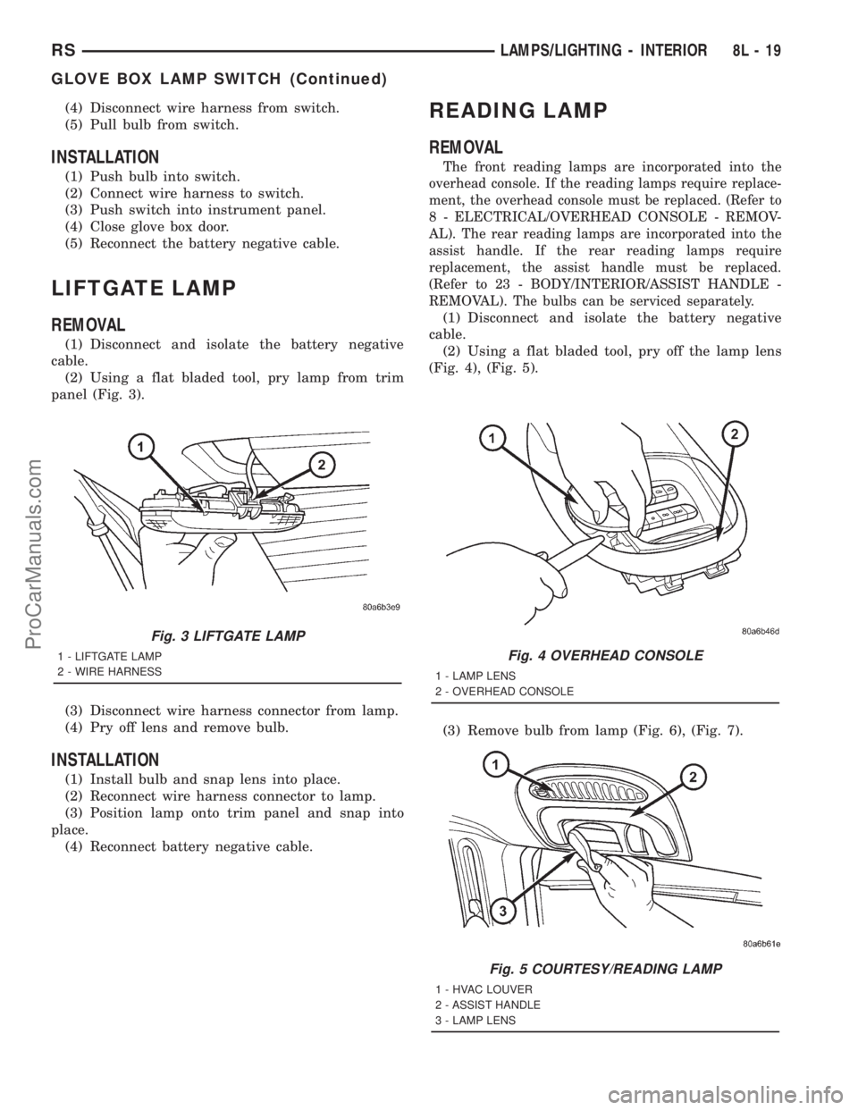
(2) Using a flat bladed tool, pry lamp from trim
panel (Fig. 3).
(3) Disconnect wire harness connector from lamp.
(4) Pry off lens and remove bulb.
INSTALLATION
(1) Install bulb and snap lens into place.
(2) Reconnect wire harness connector to lamp.
(3) Position lamp onto trim panel and snap into
place.
(4) Reconnect battery negative cable.
READING LAMP
REMOVAL
The front reading lamps are incorporated into the
overhead console. If the reading lamps require replace-
ment, the overhead console must be replaced. (Refer to
8 - ELECTRICAL/OVERHEAD CONSOLE - REMOV-
AL). The rear reading lamps are incorporated into the
assist handle. If the rear reading lamps require
replacement, the assist handle must be replaced.
(Refer to 23 - BODY/INTERIOR/ASSIST HANDLE -
REMOVAL). The bulbs can be serviced separately.
(1) Disconnect and isolate the battery negative
cable.
(2) Using a flat bladed tool, pry off the lamp lens
(Fig. 4), (Fig. 5).
(3) Remove bulb from lamp (Fig. 6), (Fig. 7).
Fig. 3 LIFTGATE LAMP
1 - LIFTGATE LAMP
2 - WIRE HARNESSFig. 4 OVERHEAD CONSOLE
1 - LAMP LENS
2 - OVERHEAD CONSOLE
Fig. 5 COURTESY/READING LAMP
1 - HVAC LOUVER
2 - ASSIST HANDLE
3 - LAMP LENS
RSLAMPS/LIGHTING - INTERIOR8L-19
GLOVE BOX LAMP SWITCH (Continued)
ProCarManuals.com