2001 DODGE TOWN AND COUNTRY battery
[x] Cancel search: batteryPage 540 of 2321
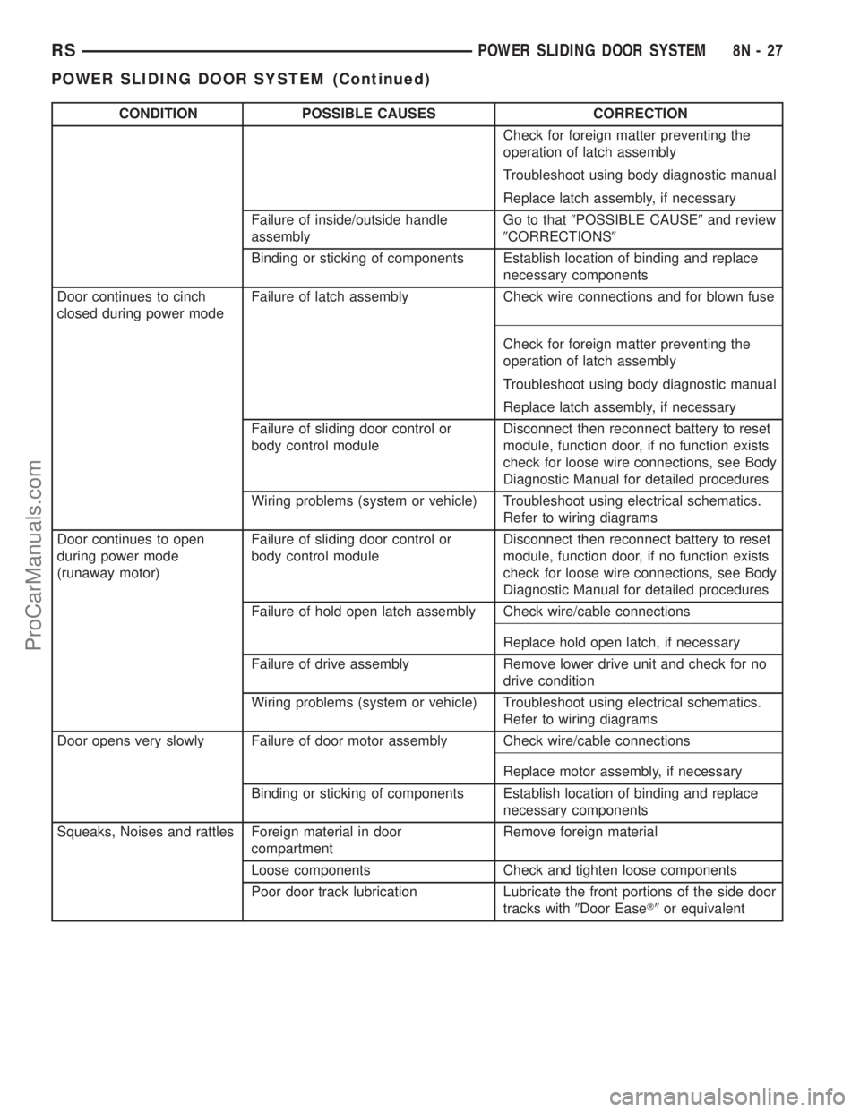
CONDITION POSSIBLE CAUSES CORRECTION
Check for foreign matter preventing the
operation of latch assembly
Troubleshoot using body diagnostic manual
Replace latch assembly, if necessary
Failure of inside/outside handle
assemblyGo to that9POSSIBLE CAUSE9and review
9CORRECTIONS9
Binding or sticking of components Establish location of binding and replace
necessary components
Door continues to cinch
closed during power modeFailure of latch assembly Check wire connections and for blown fuse
Check for foreign matter preventing the
operation of latch assembly
Troubleshoot using body diagnostic manual
Replace latch assembly, if necessary
Failure of sliding door control or
body control moduleDisconnect then reconnect battery to reset
module, function door, if no function exists
check for loose wire connections, see Body
Diagnostic Manual for detailed procedures
Wiring problems (system or vehicle) Troubleshoot using electrical schematics.
Refer to wiring diagrams
Door continues to open
during power mode
(runaway motor)Failure of sliding door control or
body control moduleDisconnect then reconnect battery to reset
module, function door, if no function exists
check for loose wire connections, see Body
Diagnostic Manual for detailed procedures
Failure of hold open latch assembly Check wire/cable connections
Replace hold open latch, if necessary
Failure of drive assembly Remove lower drive unit and check for no
drive condition
Wiring problems (system or vehicle) Troubleshoot using electrical schematics.
Refer to wiring diagrams
Door opens very slowly Failure of door motor assembly Check wire/cable connections
Replace motor assembly, if necessary
Binding or sticking of components Establish location of binding and replace
necessary components
Squeaks, Noises and rattles Foreign material in door
compartmentRemove foreign material
Loose components Check and tighten loose components
Poor door track lubrication Lubricate the front portions of the side door
tracks with9Door EaseT9or equivalent
RSPOWER SLIDING DOOR SYSTEM8N-27
POWER SLIDING DOOR SYSTEM (Continued)
ProCarManuals.com
Page 542 of 2321
LATCH
DESCRIPTION
Vehicles equipped with a power side door or doors
utilize a power latch. One power latch is used for
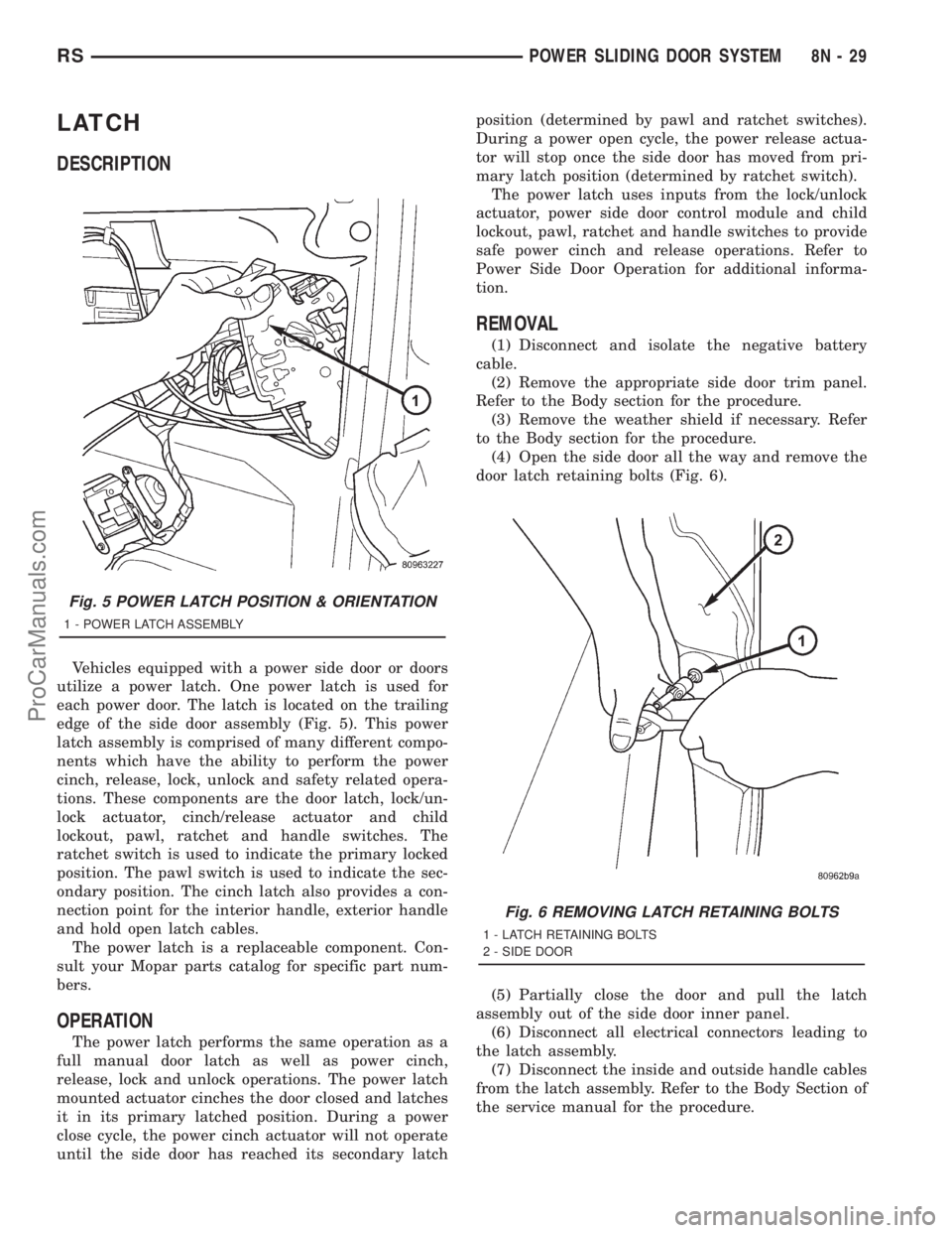
each power door. The latch is located on the trailing
edge of the side door assembly (Fig. 5). This power
latch assembly is comprised of many different compo-
nents which have the ability to perform the power
cinch, release, lock, unlock and safety related opera-
tions. These components are the door latch, lock/un-
lock actuator, cinch/release actuator and child
lockout, pawl, ratchet and handle switches. The
ratchet switch is used to indicate the primary locked
position. The pawl switch is used to indicate the sec-
ondary position. The cinch latch also provides a con-
nection point for the interior handle, exterior handle
and hold open latch cables.
The power latch is a replaceable component. Con-
sult your Mopar parts catalog for specific part num-
bers.
OPERATION
The power latch performs the same operation as a
full manual door latch as well as power cinch,
release, lock and unlock operations. The power latch
mounted actuator cinches the door closed and latches
it in its primary latched position. During a power
close cycle, the power cinch actuator will not operate
until the side door has reached its secondary latchposition (determined by pawl and ratchet switches).
During a power open cycle, the power release actua-
tor will stop once the side door has moved from pri-
mary latch position (determined by ratchet switch).
The power latch uses inputs from the lock/unlock
actuator, power side door control module and child
lockout, pawl, ratchet and handle switches to provide
safe power cinch and release operations. Refer to
Power Side Door Operation for additional informa-
tion.
REMOVAL
(1) Disconnect and isolate the negative battery
cable.
(2) Remove the appropriate side door trim panel.
Refer to the Body section for the procedure.
(3) Remove the weather shield if necessary. Refer
to the Body section for the procedure.
(4) Open the side door all the way and remove the
door latch retaining bolts (Fig. 6).
(5) Partially close the door and pull the latch
assembly out of the side door inner panel.
(6) Disconnect all electrical connectors leading to
the latch assembly.
(7) Disconnect the inside and outside handle cables
from the latch assembly. Refer to the Body Section of
the service manual for the procedure.
Fig. 5 POWER LATCH POSITION & ORIENTATION
1 - POWER LATCH ASSEMBLY
Fig. 6 REMOVING LATCH RETAINING BOLTS
1 - LATCH RETAINING BOLTS
2 - SIDE DOOR
RSPOWER SLIDING DOOR SYSTEM8N-29
ProCarManuals.com
Page 543 of 2321
(8) Disconnect the hold open latch cable from the
latch assembly. Refer to the Body Section of the ser-
vice manual for the procedure.
(9) Disconnect lock actuator link rod from the
latch assembly.
(10) Remove the latch assembly from the vehicle.
INSTALLATION
(1) Position the latch assembly in the vehicle. Be
certain all latch mounted components are installed
on the replacement latch assembly. If not, transfer
components from the old latch to the new latch
assembly.
(2) Connect the lock actuator link rod on the latch
assembly.
(3) Connect the hold open latch cable on the latch
assembly. Refer to the procedure in this section for
detailed instructions.
(4) Connect the inside and outside handle cables
on the latch assembly. Refer to the procedure in the
Body section for detailed instructions.
(5) Connect all electrical connectors leading to the
latch assembly.
(6) With assistance from another person, position
the side door and install the door latch retaining
bolts. Torque to 10 - 12 N´m (100 in. lbs.).
(7) Install the weathershield if necessary. Refer to
the procedure in the Body section for detailed
instructions.
(8) Install the appropriate side door trim panel.
Refer to the procedure in the Body section for
detailed instructions.
(9) Connect the negative battery cable.
SLIDING DOOR MOTOR
DESCRIPTION
Vehicles equipped with a power sliding door utilize
a door motor assembly. The door motor is located in
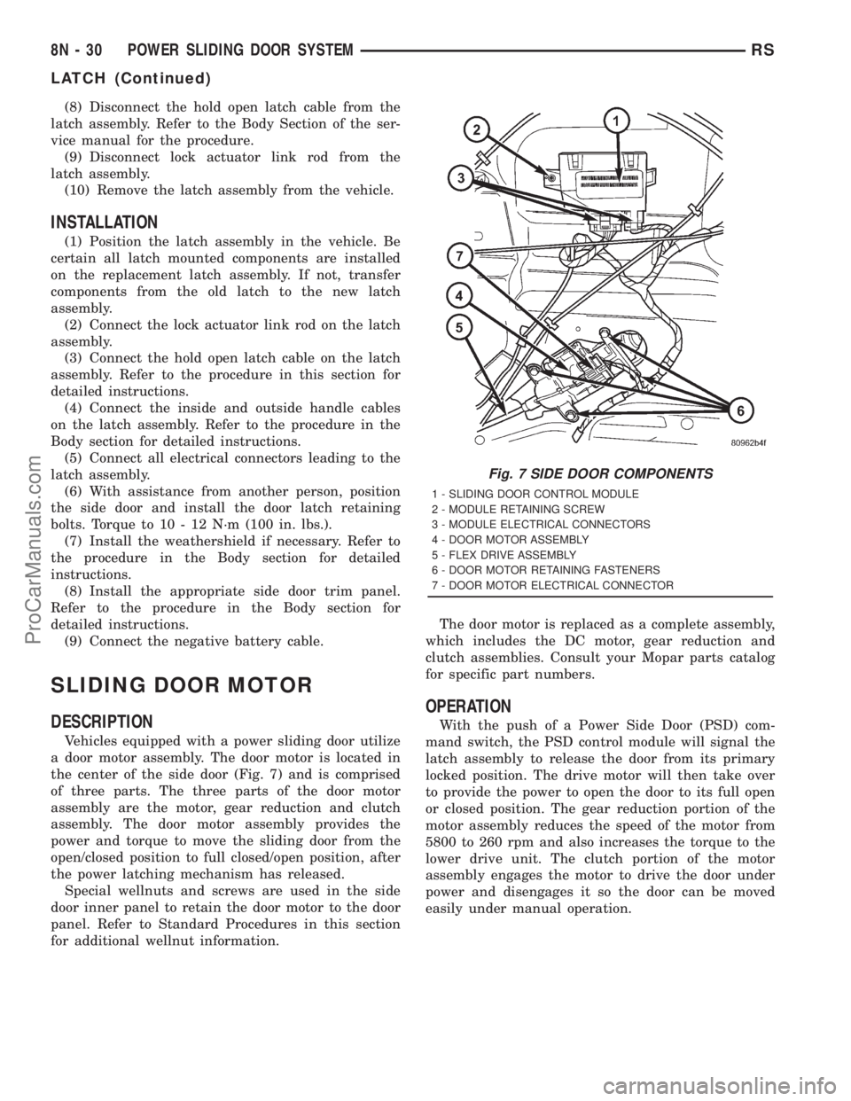
the center of the side door (Fig. 7) and is comprised
of three parts. The three parts of the door motor
assembly are the motor, gear reduction and clutch
assembly. The door motor assembly provides the
power and torque to move the sliding door from the
open/closed position to full closed/open position, after
the power latching mechanism has released.
Special wellnuts and screws are used in the side
door inner panel to retain the door motor to the door
panel. Refer to Standard Procedures in this section
for additional wellnut information.The door motor is replaced as a complete assembly,
which includes the DC motor, gear reduction and
clutch assemblies. Consult your Mopar parts catalog
for specific part numbers.
OPERATION
With the push of a Power Side Door (PSD) com-
mand switch, the PSD control module will signal the
latch assembly to release the door from its primary
locked position. The drive motor will then take over
to provide the power to open the door to its full open
or closed position. The gear reduction portion of the
motor assembly reduces the speed of the motor from
5800 to 260 rpm and also increases the torque to the
lower drive unit. The clutch portion of the motor
assembly engages the motor to drive the door under
power and disengages it so the door can be moved
easily under manual operation.
Fig. 7 SIDE DOOR COMPONENTS
1 - SLIDING DOOR CONTROL MODULE
2 - MODULE RETAINING SCREW
3 - MODULE ELECTRICAL CONNECTORS
4 - DOOR MOTOR ASSEMBLY
5 - FLEX DRIVE ASSEMBLY
6 - DOOR MOTOR RETAINING FASTENERS
7 - DOOR MOTOR ELECTRICAL CONNECTOR
8N - 30 POWER SLIDING DOOR SYSTEMRS
LATCH (Continued)
ProCarManuals.com
Page 544 of 2321
REMOVAL
(1) Disconnect and isolate the negative battery
cable.
(2) Remove the door trim panel from the appropri-
ate side door. Refer to the Body section for the pro-
cedure.
(3) Remove water shield as necessary to gain
access to motor assembly.
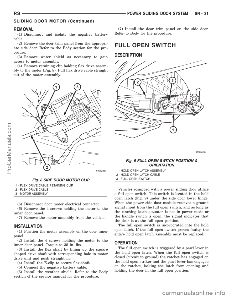
(4) Remove retaining clip holding flex drive assem-
bly to the motor (Fig. 8). Pull flex drive cable straight
out of the motor assembly.
(5) Disconnect door motor electrical connector.
(6) Remove the 4 screws holding the motor to the
inner door panel.
(7) Remove the motor assembly from the vehicle.
INSTALLATION
(1) Position the motor assembly on the door inner
panel.
(2) Install the 4 screws holding the motor to the
inner door panel. Torque to 35 in. lbs.
(3) Install the flex shaft by lining up the square
shaped drive shaft with corresponding hole in motor
drive unit and push straight in.
(4) Install the E-clip to secure flex-shaft.
(5) Connect the negative battery cable.
(6) Install the weather shield. Refer to the Body
section of the service manual for the procedure.(7) Install the door trim panel on the side door.
Refer to Body for the procedure.
FULL OPEN SWITCH
DESCRIPTION
Vehicles equipped with a power sliding door utilize
a full open switch. This switch is located in the hold
open latch (Fig. 9) under the side door lower hinge.
When the power side door module receives a ground
signal input from the full open switch, and as long as
the cinching latch actuator is not in power mode or
the handle switch is open, the signal indicates that
the door is at the full open position.
The full open switch is incorporated into the hold
open latch. If the full open switch proves faulty, the
entire hold open latch assembly must be replaced.
OPERATION
The full open switch is triggered by a pawl lever in
the hold open latch. When the full open switch is
closed (circuit to ground) the ratchet has engaged on
the hold open striker and the pawl lever has engaged
on the ratchet, locking the latch from opening and
holding the door in the full open position.
Fig. 8 SIDE DOOR MOTOR CLIP
1 - FLEX DRIVE CABLE RETAINING CLIP
2 - FLEX DRIVE CABLE
3 - MOTOR ASSEMBLY
Fig. 9 FULL OPEN SWITCH POSITION &
ORIENTATION
1 - HOLD OPEN LATCH ASSEMBLY
2 - HOLD OPEN LATCH CABLE
3 - FULL OPEN SWITCH
RSPOWER SLIDING DOOR SYSTEM8N-31
SLIDING DOOR MOTOR (Continued)
ProCarManuals.com
Page 545 of 2321
LEFT B-PILLAR SWITCH
DESCRIPTION
Vehicles equipped with power sliding side door/s
utilize B-pillar switches. These switches are located
on the interior of the vehicle, on the B-pillar trim
panels. These switches serve as an open and close
command switch for the appropriate power side door.
The B-pillar switches are replaceable. Consult your
Mopar parts catalog for a specific part number.
OPERATION
When the Pillar switch is depressed a signal is
sent to the Body Control Module (BCM), this signal
is then sent to the Power Sliding Door Module, tell-
ing it to start a power open or close cycle. The child
lockout feature must be disabled and the side door
must be unlocked in order for the Pillar switch to
function.
REMOVAL
(1) Disconnect and isolate the negative battery
cable.
(2) Using a trim stick or other small flat-bladed
pry tool, gently pry the leading upper edge of the
B-pillar switch away from the B-pillar trim.
(3) Once the upper edge is free from pillar trim,
rock the switch out of the switch opening.
(4) Disconnect the B-pillar switch electrical con-
nector. First, slide the connector lock away from the
switch then, depress connector retaining tab while
pulling straight apart.
(5) Remove the B-pillar switch from the vehicle.
INSTALLATION
(1) Connect the B-pillar switch electrical connector.
Slide connector lock toward the switch to lock in
place.
(2) Hook the lower edge of the B-pillar switch on
the B-pillar trim and then push the switch firmly
into position.
(3) Connect the negative battery cable.
RIGHT B-PILLAR SWITCH
DESCRIPTION
Vehicles equipped with power sliding side door/s
utilize B-pillar switches. These switches are located
on the interior of the vehicle, on the B-pillar trim
panels. These switches serve as an open and close
command switch for the appropriate power side door.
The B-pillar switches are replaceable. Consult your
Mopar parts catalog for a specific part number.
OPERATION
When the Pillar switch is depressed a signal is
sent to the Body Control Module (BCM), this signal
is then sent to the Power Sliding Door Module, tell-
ing it to start a power open or close cycle. The child
lockout feature must be disabled and the side door
must be unlocked in order for the Pillar switch to
function.
REMOVAL
(1) Disconnect and isolate the negative battery
cable.
(2) Using a trim stick or other small flat-bladed
pry tool, gently pry the leading upper edge of the
B-pillar switch away from the B-pillar trim.
(3) Once the upper edge is free from pillar trim,
rock the switch out of the switch opening.
(4) Disconnect the B-pillar switch electrical con-
nector. First, slide the connector lock away from the
switch then, depress connector retaining tab while
pulling straight apart.
(5) Remove the B-pillar switch from the vehicle.
INSTALLATION
(1) Connect the B-pillar switch electrical connector.
Slide connector lock toward the switch to lock in
place.
(2) Hook the lower edge of the B-pillar switch on
the B-pillar trim and then push the switch firmly
into position.
(3) Connect the negative battery cable.
8N - 32 POWER SLIDING DOOR SYSTEMRS
ProCarManuals.com
Page 546 of 2321
LOWER DRIVE UNIT
DESCRIPTION
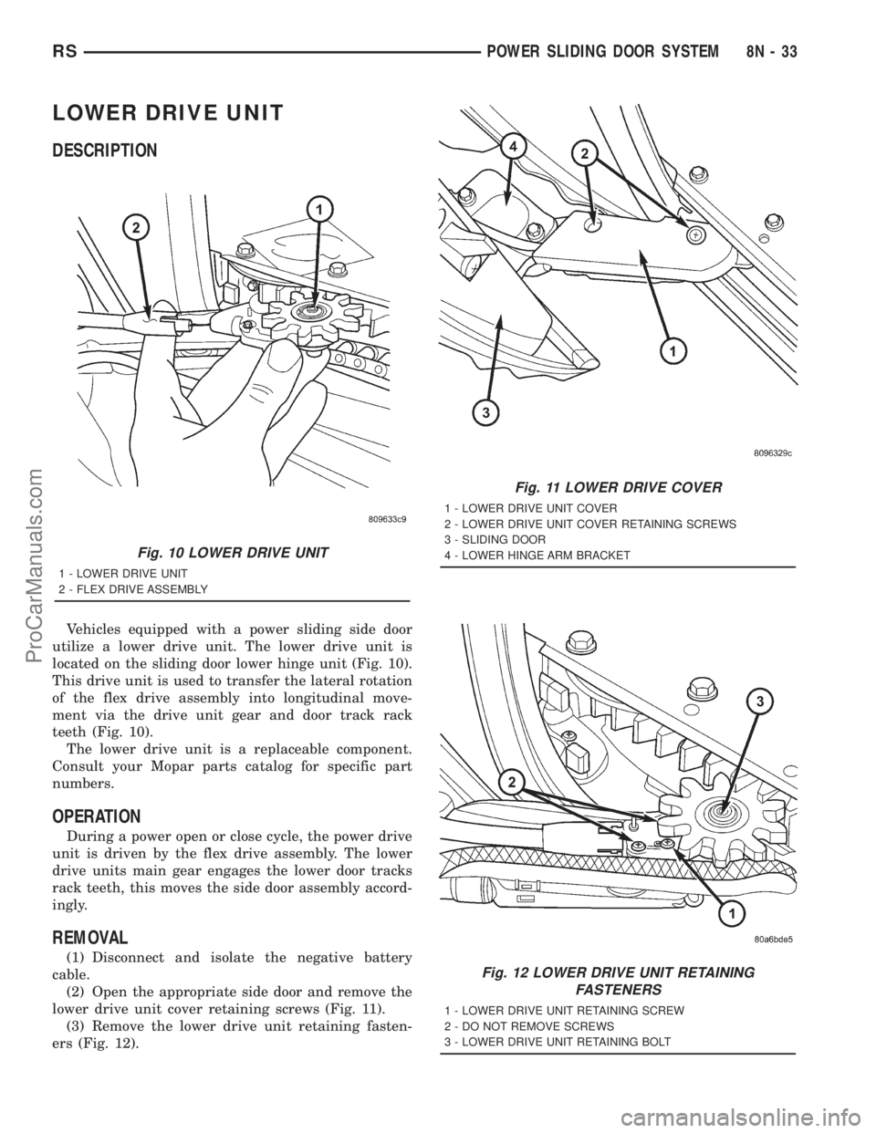
Vehicles equipped with a power sliding side door
utilize a lower drive unit. The lower drive unit is
located on the sliding door lower hinge unit (Fig. 10).
This drive unit is used to transfer the lateral rotation
of the flex drive assembly into longitudinal move-
ment via the drive unit gear and door track rack
teeth (Fig. 10).
The lower drive unit is a replaceable component.
Consult your Mopar parts catalog for specific part
numbers.
OPERATION
During a power open or close cycle, the power drive
unit is driven by the flex drive assembly. The lower
drive units main gear engages the lower door tracks
rack teeth, this moves the side door assembly accord-
ingly.
REMOVAL
(1) Disconnect and isolate the negative battery
cable.
(2) Open the appropriate side door and remove the
lower drive unit cover retaining screws (Fig. 11).
(3) Remove the lower drive unit retaining fasten-
ers (Fig. 12).
Fig. 10 LOWER DRIVE UNIT
1 - LOWER DRIVE UNIT
2 - FLEX DRIVE ASSEMBLY
Fig. 11 LOWER DRIVE COVER
1 - LOWER DRIVE UNIT COVER
2 - LOWER DRIVE UNIT COVER RETAINING SCREWS
3 - SLIDING DOOR
4 - LOWER HINGE ARM BRACKET
Fig. 12 LOWER DRIVE UNIT RETAINING
FASTENERS
1 - LOWER DRIVE UNIT RETAINING SCREW
2 - DO NOT REMOVE SCREWS
3 - LOWER DRIVE UNIT RETAINING BOLT
RSPOWER SLIDING DOOR SYSTEM8N-33
ProCarManuals.com
Page 547 of 2321
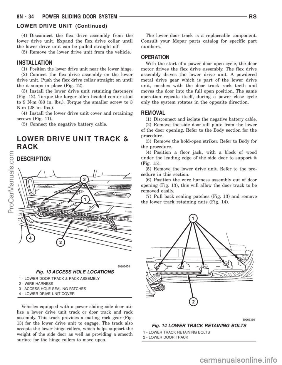
(4) Disconnect the flex drive assembly from the
lower drive unit. Expand the flex drive collar until
the lower drive unit can be pulled straight off.
(5) Remove the lower drive unit from the vehicle.
INSTALLATION
(1)Position the lower drive unit near the lower hinge.
(2) Connect the flex drive assembly on the lower
drive unit. Push the flex drive collar straight on until
the it snaps in place (Fig. 12).
(3) Install the lower drive unit retaining fasteners
(Fig. 12). Torque the larger allen headed center stud
to 9 N´m (80 in. lbs.). Torque the smaller screw to 3
N´m (28 in. lbs.).
(4) Install the lower drive unit cover and retaining
screws (Fig. 11).
(5) Connect the negative battery cable.
LOWER DRIVE UNIT TRACK &
RACK
DESCRIPTION
Vehicles equipped with a power sliding side door uti-
lize a lower drive unit track or door track and rack
assembly. This track provides a mating rack gear (Fig.
13) for the lower drive unit to engage. The track also
accepts the lower hinge rollers, which helps support the
weight of the side door as well as providing a smooth
surface for the hinge rollers to move upon.
The lower door track is a replaceable component.
Consult your Mopar parts catalog for specific part
numbers.
OPERATION
With the start of a power door open cycle, the door
motor drives the flex drive assembly. The flex drive
assembly drives the lower drive unit. A powdered
metal drive gear which is part of the lower drive
unit, meshes with the door track rack teeth and
moves the door into the full open position. The same
operation repeats itself, during a power close cycle
only the system rotates in the opposite direction.
REMOVAL
(1)Disconnect and isolate the negative battery cable.
(2) Remove the side door sill plate from the lower
of the door opening. Refer to the Body section for the
procedure.
(3) Remove the hold-open striker. Refer to Body for
the procedure.
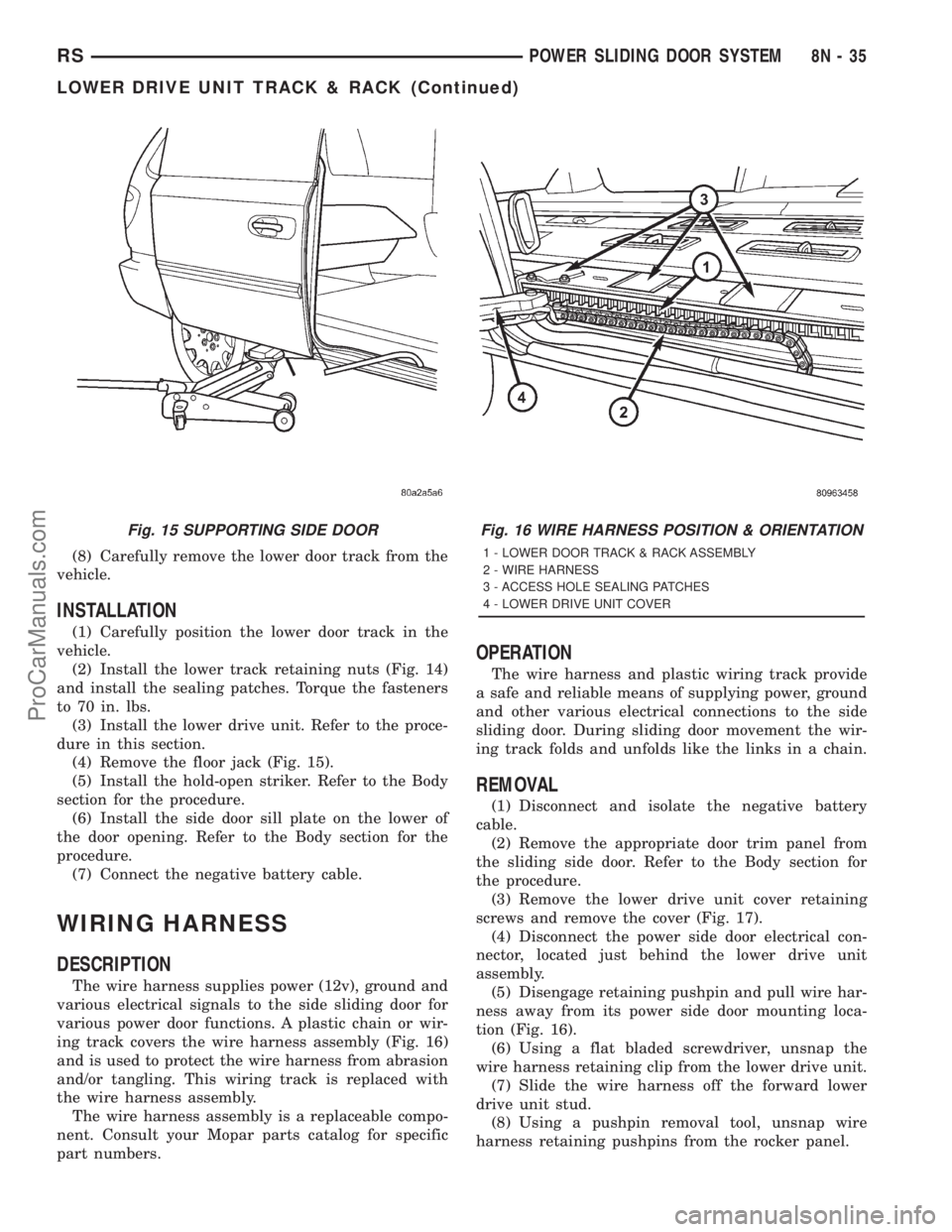
(4) Position a floor jack, with a block of wood
under the leading edge of the side door to support it
(Fig. 15).
(5) Remove the lower drive unit. Refer to the pro-
cedure in this section.
(6) Position the wire harness assembly out of door
opening (Fig. 13), this will allow the door track to be
removed easily.
(7) Pull back sealing patches (Fig. 13) and remove
the lower track retaining nuts (Fig. 14).
Fig. 13 ACCESS HOLE LOCATIONS
1 - LOWER DOOR TRACK & RACK ASSEMBLY
2 - WIRE HARNESS
3 - ACCESS HOLE SEALING PATCHES
4 - LOWER DRIVE UNIT COVER
Fig. 14 LOWER TRACK RETAINING BOLTS
1 - LOWER TRACK RETAINING BOLTS
2 - LOWER DOOR TRACK
8N - 34 POWER SLIDING DOOR SYSTEMRS
LOWER DRIVE UNIT (Continued)
ProCarManuals.com
Page 548 of 2321
(8) Carefully remove the lower door track from the
vehicle.
INSTALLATION
(1) Carefully position the lower door track in the
vehicle.
(2) Install the lower track retaining nuts (Fig. 14)
and install the sealing patches. Torque the fasteners
to 70 in. lbs.
(3) Install the lower drive unit. Refer to the proce-
dure in this section.
(4) Remove the floor jack (Fig. 15).
(5) Install the hold-open striker. Refer to the Body
section for the procedure.
(6) Install the side door sill plate on the lower of
the door opening. Refer to the Body section for the
procedure.
(7) Connect the negative battery cable.
WIRING HARNESS
DESCRIPTION
The wire harness supplies power (12v), ground and
various electrical signals to the side sliding door for
various power door functions. A plastic chain or wir-
ing track covers the wire harness assembly (Fig. 16)
and is used to protect the wire harness from abrasion
and/or tangling. This wiring track is replaced with
the wire harness assembly.
The wire harness assembly is a replaceable compo-
nent. Consult your Mopar parts catalog for specific
part numbers.
OPERATION
The wire harness and plastic wiring track provide
a safe and reliable means of supplying power, ground
and other various electrical connections to the side
sliding door. During sliding door movement the wir-
ing track folds and unfolds like the links in a chain.
REMOVAL
(1) Disconnect and isolate the negative battery
cable.
(2) Remove the appropriate door trim panel from
the sliding side door. Refer to the Body section for
the procedure.
(3) Remove the lower drive unit cover retaining
screws and remove the cover (Fig. 17).
(4) Disconnect the power side door electrical con-
nector, located just behind the lower drive unit
assembly.
(5) Disengage retaining pushpin and pull wire har-
ness away from its power side door mounting loca-
tion (Fig. 16).
(6) Using a flat bladed screwdriver, unsnap the
wire harness retaining clip from the lower drive unit.
(7) Slide the wire harness off the forward lower
drive unit stud.
(8) Using a pushpin removal tool, unsnap wire
harness retaining pushpins from the rocker panel.
Fig. 15 SUPPORTING SIDE DOORFig. 16 WIRE HARNESS POSITION & ORIENTATION
1 - LOWER DOOR TRACK & RACK ASSEMBLY
2 - WIRE HARNESS
3 - ACCESS HOLE SEALING PATCHES
4 - LOWER DRIVE UNIT COVER
RSPOWER SLIDING DOOR SYSTEM8N-35
LOWER DRIVE UNIT TRACK & RACK (Continued)
ProCarManuals.com