2001 DODGE TOWN AND COUNTRY battery
[x] Cancel search: batteryPage 530 of 2321
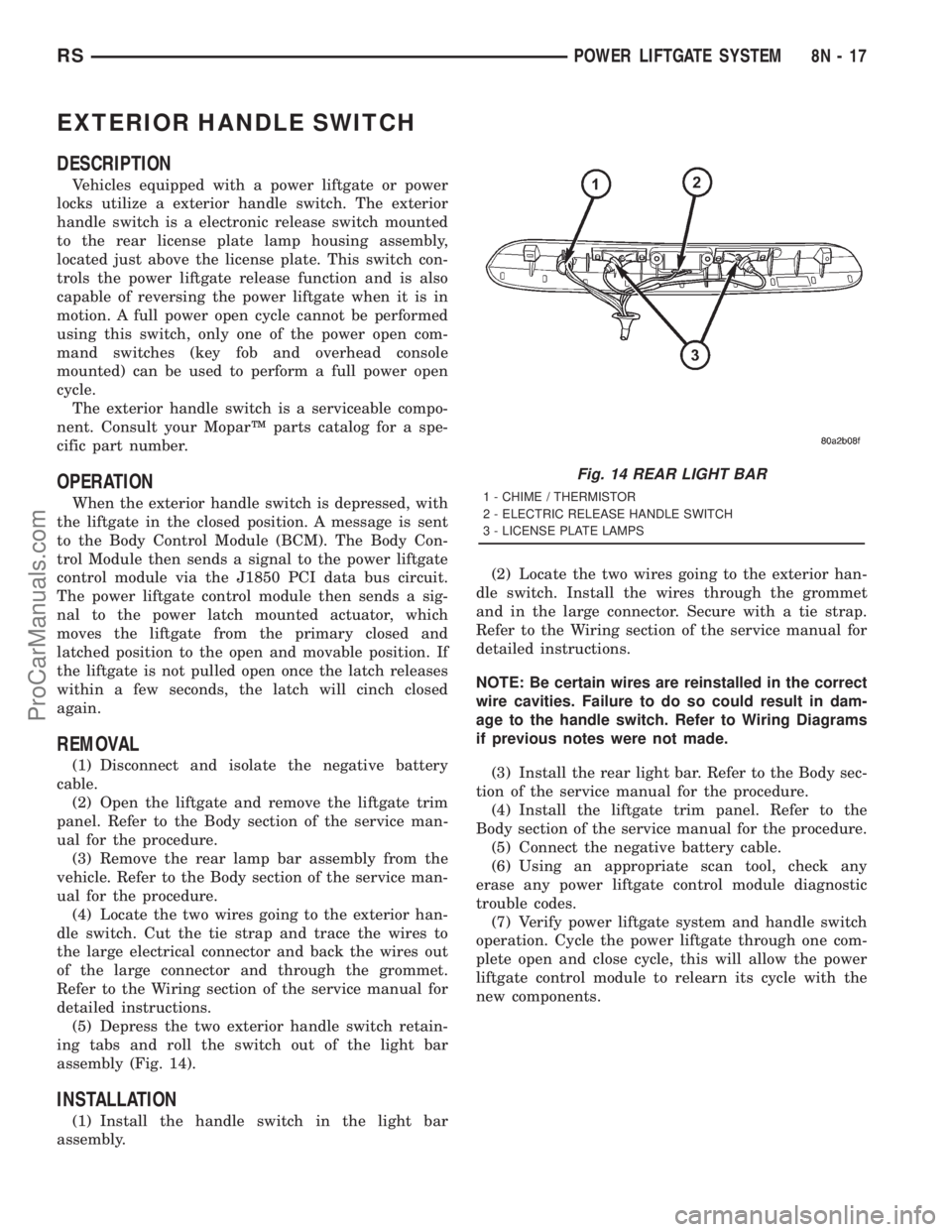
EXTERIOR HANDLE SWITCH
DESCRIPTION
Vehicles equipped with a power liftgate or power
locks utilize a exterior handle switch. The exterior
handle switch is a electronic release switch mounted
to the rear license plate lamp housing assembly,
located just above the license plate. This switch con-
trols the power liftgate release function and is also
capable of reversing the power liftgate when it is in
motion. A full power open cycle cannot be performed
using this switch, only one of the power open com-
mand switches (key fob and overhead console
mounted) can be used to perform a full power open
cycle.
The exterior handle switch is a serviceable compo-
nent. Consult your MoparŸ parts catalog for a spe-
cific part number.
OPERATION
When the exterior handle switch is depressed, with
the liftgate in the closed position. A message is sent
to the Body Control Module (BCM). The Body Con-
trol Module then sends a signal to the power liftgate
control module via the J1850 PCI data bus circuit.
The power liftgate control module then sends a sig-
nal to the power latch mounted actuator, which
moves the liftgate from the primary closed and
latched position to the open and movable position. If
the liftgate is not pulled open once the latch releases
within a few seconds, the latch will cinch closed
again.
REMOVAL
(1) Disconnect and isolate the negative battery
cable.
(2) Open the liftgate and remove the liftgate trim
panel. Refer to the Body section of the service man-
ual for the procedure.
(3) Remove the rear lamp bar assembly from the
vehicle. Refer to the Body section of the service man-
ual for the procedure.
(4) Locate the two wires going to the exterior han-
dle switch. Cut the tie strap and trace the wires to
the large electrical connector and back the wires out
of the large connector and through the grommet.
Refer to the Wiring section of the service manual for
detailed instructions.
(5) Depress the two exterior handle switch retain-
ing tabs and roll the switch out of the light bar
assembly (Fig. 14).
INSTALLATION
(1) Install the handle switch in the light bar
assembly.(2) Locate the two wires going to the exterior han-
dle switch. Install the wires through the grommet
and in the large connector. Secure with a tie strap.
Refer to the Wiring section of the service manual for
detailed instructions.
NOTE: Be certain wires are reinstalled in the correct
wire cavities. Failure to do so could result in dam-
age to the handle switch. Refer to Wiring Diagrams
if previous notes were not made.
(3) Install the rear light bar. Refer to the Body sec-
tion of the service manual for the procedure.
(4) Install the liftgate trim panel. Refer to the
Body section of the service manual for the procedure.
(5) Connect the negative battery cable.
(6) Using an appropriate scan tool, check any
erase any power liftgate control module diagnostic
trouble codes.
(7) Verify power liftgate system and handle switch
operation. Cycle the power liftgate through one com-
plete open and close cycle, this will allow the power
liftgate control module to relearn its cycle with the
new components.
Fig. 14 REAR LIGHT BAR
1 - CHIME / THERMISTOR
2 - ELECTRIC RELEASE HANDLE SWITCH
3 - LICENSE PLATE LAMPS
RSPOWER LIFTGATE SYSTEM8N-17
ProCarManuals.com
Page 531 of 2321

CHIME/THERMISTOR
DESCRIPTION
Vehicles equipped with a power liftgate utilize a
chime/thermistor assembly. The chime/thermistor
assembly is a small capacitor shaped electrical com-
ponent mounted to the rear license plate lamp hous-
ing assembly (Fig. 15), located just above the license
plate. The chime portion of the assembly controls the
audible chime sound heard at the rear of the vehicle
when the power liftgate is in motion. The thermistor
portion of the assembly is a temperature sensor, used
by the power liftgate module.
The chime/thermistor assembly is a serviceable
component. Consult your MoparŸ parts catalog for a
specific part number.
OPERATION
The chime/thermistor assembly performs two dif-
ferent functions for the power liftgate system. First,
the chime portion provides an audible chime sound
which is controlled by the power liftgate module. The
chime/thermistor assembly is hardwired to the power
liftgate module. Second the thermistor provides a
outside temperature reading by way of a resistance
reading (V- ohms) supplied to the power liftgate
module. As temperature increases the resistance
reading (V- ohms) increases, as temperature
decreases the resistance reading (V- ohms)
decreases.
REMOVAL
(1) Disconnect and isolate the negative battery
cable.
(2) Remove the rear light bar assembly from the
vehicle. Refer to Body for the procedure.
(3) Using your hands, grasp the light bar at its
sides next to thermistor/chime assembly and gently
pull the two sides of the light bar apart until the
thermistor/chime assembly can be removed.
INSTALLATION
(1) Gently pull the two sides of the light bar apart
until the thermistor/chime assembly can be installed.
(2) Install the rear light bar assembly on the vehi-
cle. Refer to the Body section of the service manual
for the procedure.
(3) Connect the negative battery cable.
Fig. 15 REAR LIGHT BAR
1 - CHIME / THERMISTOR
2 - ELECTRIC RELEASE HANDLE SWITCH
3 - LICENSE PLATE LAMPS
8N - 18 POWER LIFTGATE SYSTEMRS
ProCarManuals.com
Page 533 of 2321
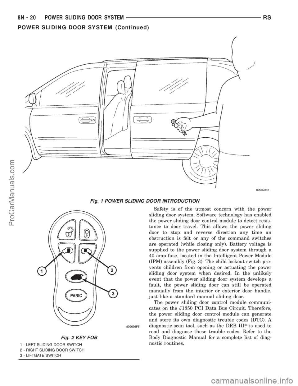
Safety is of the utmost concern with the power
sliding door system. Software technology has enabled
the power sliding door control module to detect resis-
tance to door travel. This allows the power sliding
door to stop and reverse direction any time an
obstruction is felt or any of the command switches
are operated (while closing only). Battery voltage is
supplied to the power sliding door system through a
40 amp fuse, located in the Intelligent Power Module
(IPM) assembly (Fig. 3). The child lockout switch pre-
vents children from opening or actuating the power
sliding door system when desired. In the unlikely
event that the power sliding door system develops a
fault, the power sliding door can still be operated
manually from the interior or exterior door handle,
just like a standard manual sliding door.
The power sliding door control module communi-
cates on the J1850 PCI Data Bus Circuit. Therefore,
the power sliding door control module can generate
and store its own diagnostic trouble codes (DTC). A
diagnostic scan tool, such as the DRB IIItis used to
read and diagnose these trouble codes. Refer to the
Body Diagnostic Manual for a complete list of diag-
nostic routines.
Fig. 1 POWER SLIDING DOOR INTRODUCTION
Fig. 2 KEY FOB
1 - LEFT SLIDING DOOR SWITCH
2 - RIGHT SLIDING DOOR SWITCH
3 - LIFTGATE SWITCH
8N - 20 POWER SLIDING DOOR SYSTEMRS
POWER SLIDING DOOR SYSTEM (Continued)
ProCarManuals.com
Page 535 of 2321
POWER SLIDING DOOR SYSTEM WARNINGS
WARNING: ALWAYS DISCONNECT THE NEGATIVE
BATTERY CABLE BEFORE ATTEMPTING ANY
POWER SLIDING DOOR SYSTEM SERVICE.
WARNING: EXTREME CARE MUST BE TAKEN TO
PREVENT OBJECTS FROM ENTERING THE DOORS
PATH ONCE THE DOOR REACHES THE CINCH
MOTOR CONTACT (APPROXIMATELY 1 INCH
BEFORE FULLY CLOSED).
WARNING: NEVER ATTEMPT TO ENTER OR EXIT
THE VEHICLE WHILE THE POWER SLIDING DOOR
IS IN MOTION. YOU COULD DAMAGE THE POWER
SLIDING DOOR SYSTEM OR COMPONENTS
AND/OR CAUSE PERSONAL INJURY.
WARNING: NEVER ATTEMPT TO DRIVE AWAY WITH
THE POWER SLIDING DOOR IN MOTION. YOU
COULD DAMAGE THE POWER SLIDING DOOR SYS-
TEM OR COMPONENTS AND/OR CAUSE PER-
SONAL INJURY.
WARNING: NEVER STICK OBJECTS IN THE POWER
SLIDING DOOR WHEN CINCHING CLOSED. YOU
COULD DAMAGE THE VEHICLE, POWER SLIDING
DOOR SYSTEM OR COMPONENTS AND/OR CAUSE
PERSONAL INJURY.
DIAGNOSIS AND TESTING - POWER SLIDING
DOOR SYSTEM
The power opening and closing power sliding door
system is a complex system containing many compo-
nents and modules. In order to obtain conclusive
testing, the Programmable Communications Interface
(J1850) data bus network and all of the electronic
modules that provide inputs to, or receive outputs
from the power sliding door system must be checked.
The power sliding door system was designed to be
diagnosed with an appropriate diagnostic scan tool,
such as the DRB IIIt. The most reliable, efficient,
and accurate means to diagnose the power sliding
door system requires the use of a DRB IIItscan tool
and the proper Body Diagnostic Procedures manual.
The DRB IIItcan be used to observe various switch
statuses throughout the power sliding door system to
help the technician diagnose a defective switch or
component. The DRB IIItcan also be used to actuate
various components throughout the power sliding
door system to help the technician diagnose a defec-
tive component.
Before any testing of the power sliding door system
is attempted, the battery should be fully charged, all
built-in power sliding door system inhibitors read
and understood (Refer to 8 - ELECTRICAL/POWER
DOORS - OPERATION) and all wire harness and
ground connections inspected around the affected
areas on the vehicle.
The following are quick reference diagnostic tables
to help when diagnosing and testing the power slid-
ing door system.
8N - 22 POWER SLIDING DOOR SYSTEMRS
POWER SLIDING DOOR SYSTEM (Continued)
ProCarManuals.com
Page 536 of 2321
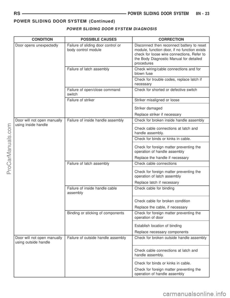
POWER SLIDING DOOR SYSTEM DIAGNOSIS
CONDITION POSSIBLE CAUSES CORRECTION
Door opens unexpectedly Failure of sliding door control or
body control moduleDisconnect then reconnect battery to reset
module, function door, if no function exists
check for loose wire connections, Refer to
the Body Diagnostic Manual for detailed
procedures
Failure of latch assembly Check wiring/cable connections and for
blown fuse
Check for trouble codes, replace latch if
necessary
Failure of open/close command
switchCheck for shorted or defective switch
Failure of striker Striker misaligned or loose
Striker damaged
Replace striker if necessary
Door will not open manually
using inside handleFailure of inside handle assembly Check for broken inside handle assembly
Check cable connections at latch and
handle assembly.
Check for binds or kinks in cable.
Check for foreign matter preventing the
operation of handle assembly
Replace the handle if necessary
Failure of latch assembly Check cable connections
Check for foreign matter preventing the
operation of latch assembly
Replace latch if necessary
Failure of inside handle cable
assemblyCheck cable for binding
Check cable for broken condition
Replace the cable, if necessary
Binding or sticking of components Check for foreign matter preventing the
operation of door
Establish location of binding
Replace necessary components
Door will not open manually
using outside handleFailure of outside handle assembly Check for broken outside handle assembly
Check cable connections at latch and
handle assembly.
Check for binds or kinks in cable.
Check for foreign matter preventing the
operation of handle assembly
RSPOWER SLIDING DOOR SYSTEM8N-23
POWER SLIDING DOOR SYSTEM (Continued)
ProCarManuals.com
Page 537 of 2321
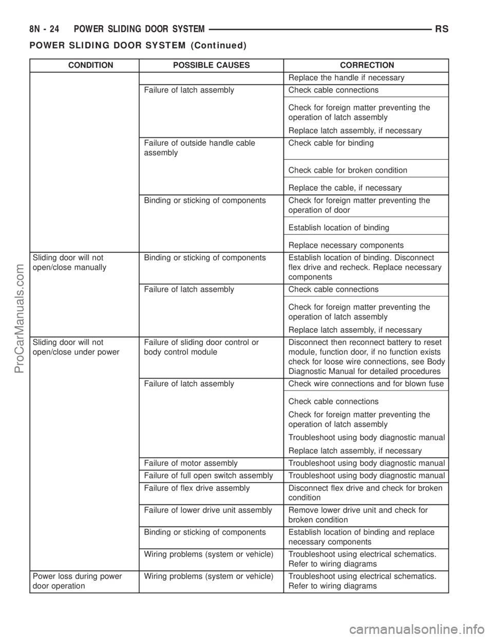
CONDITION POSSIBLE CAUSES CORRECTION
Replace the handle if necessary
Failure of latch assembly Check cable connections
Check for foreign matter preventing the
operation of latch assembly
Replace latch assembly, if necessary
Failure of outside handle cable
assemblyCheck cable for binding
Check cable for broken condition
Replace the cable, if necessary
Binding or sticking of components Check for foreign matter preventing the
operation of door
Establish location of binding
Replace necessary components
Sliding door will not
open/close manuallyBinding or sticking of components Establish location of binding. Disconnect
flex drive and recheck. Replace necessary
components
Failure of latch assembly Check cable connections
Check for foreign matter preventing the
operation of latch assembly
Replace latch assembly, if necessary
Sliding door will not
open/close under powerFailure of sliding door control or
body control moduleDisconnect then reconnect battery to reset
module, function door, if no function exists
check for loose wire connections, see Body
Diagnostic Manual for detailed procedures
Failure of latch assembly Check wire connections and for blown fuse
Check cable connections
Check for foreign matter preventing the
operation of latch assembly
Troubleshoot using body diagnostic manual
Replace latch assembly, if necessary
Failure of motor assembly Troubleshoot using body diagnostic manual
Failure of full open switch assembly Troubleshoot using body diagnostic manual
Failure of flex drive assembly Disconnect flex drive and check for broken
condition
Failure of lower drive unit assembly Remove lower drive unit and check for
broken condition
Binding or sticking of components Establish location of binding and replace
necessary components
Wiring problems (system or vehicle) Troubleshoot using electrical schematics.
Refer to wiring diagrams
Power loss during power
door operationWiring problems (system or vehicle) Troubleshoot using electrical schematics.
Refer to wiring diagrams
8N - 24 POWER SLIDING DOOR SYSTEMRS
POWER SLIDING DOOR SYSTEM (Continued)
ProCarManuals.com
Page 538 of 2321
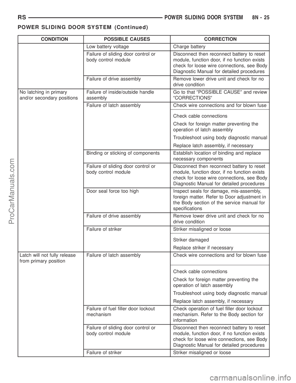
CONDITION POSSIBLE CAUSES CORRECTION
Low battery voltage Charge battery
Failure of sliding door control or
body control moduleDisconnect then reconnect battery to reset
module, function door, if no function exists
check for loose wire connections, see Body
Diagnostic Manual for detailed procedures
Failure of drive assembly Remove lower drive unit and check for no
drive condition
No latching in primary
and/or secondary positionsFailure of inside/outside handle
assemblyGo to that9POSSIBLE CAUSE9and review
9CORRECTIONS9
Failure of latch assembly Check wire connections and for blown fuse
Check cable connections
Check for foreign matter preventing the
operation of latch assembly
Troubleshoot using body diagnostic manual
Replace latch assembly, if necessary
Binding or sticking of components Establish location of binding and replace
necessary components
Failure of sliding door control or
body control moduleDisconnect then reconnect battery to reset
module, function door, if no function exists
check for loose wire connections, see Body
Diagnostic Manual for detailed procedures
Door seal force too high Inspect seals for damage, mis-assembly,
foreign matter. Refer to Door adjustment in
the Body section of the service manual for
specifications
Failure of drive assembly Remove lower drive unit and check for no
drive condition
Failure of striker Striker misaligned or loose
Striker damaged
Replace striker if necessary
Latch will not fully release
from primary positionFailure of latch assembly Check wire connections and for blown fuse
Check cable connections
Check for foreign matter preventing the
operation of latch assembly
Troubleshoot using body diagnostic manual
Replace latch assembly, if necessary
Failure of fuel filler door lockout
mechanismCheck operation of fuel filler door lockout
mechanism. Refer to the Body section for
information
Failure of sliding door control or
body control moduleDisconnect then reconnect battery to reset
module, function door, if no function exists
check for loose wire connections, see Body
Diagnostic Manual for detailed procedures
Failure of striker Striker misaligned or loose
RSPOWER SLIDING DOOR SYSTEM8N-25
POWER SLIDING DOOR SYSTEM (Continued)
ProCarManuals.com
Page 539 of 2321
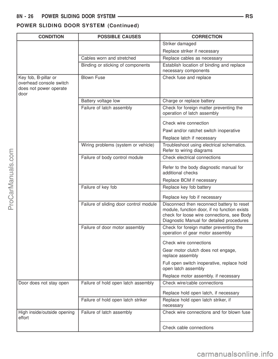
CONDITION POSSIBLE CAUSES CORRECTION
Striker damaged
Replace striker if necessary
Cables worn and stretched Replace cables as necessary
Binding or sticking of components Establish location of binding and replace
necessary components
Key fob, B-pillar or
overhead console switch
does not power operate
doorBlown Fuse Check fuse and replace
Battery voltage low Charge or replace battery
Failure of latch assembly Check for foreign matter preventing the
operation of latch assembly
Check wire connection
Pawl and/or ratchet switch inoperative
Replace latch if necessary
Wiring problems (system or vehicle) Troubleshoot using electrical schematics.
Refer to wiring diagrams
Failure of body control module Check electrical connections
Refer to the body diagnostic manual for
additional checks
Replace BCM if necessary
Failure of key fob Replace key fob battery
Replace key fob if necessary
Failure of sliding door control module Disconnect then reconnect battery to reset
module, function door, if no function exists
check for loose wire connections, see Body
Diagnostic Manual for detailed procedures
Failure of door motor assembly Check for foreign matter preventing the
operation of gear motor assembly
Check wire connections
Gear motor clutch does not engage,
replace assembly
Full open switch inoperative, replace hold
open latch assembly
Replace motor assembly. if necessary
Door does not stay open Failure of hold open latch assembly Check wire/cable connections
Replace hold open latch, if necessary
Failure of hold open latch striker Replace hold open latch striker, if
necessary
High inside/outside opening
effortFailure of latch assembly Check wire connections and for blown fuse
Check cable connections
8N - 26 POWER SLIDING DOOR SYSTEMRS
POWER SLIDING DOOR SYSTEM (Continued)
ProCarManuals.com