2001 DODGE TOWN AND COUNTRY wheel bolts
[x] Cancel search: wheel boltsPage 61 of 2321
The lower control arm is an iron casting with two
rubber bushings and a ball joint. The lower control
arm front bushing is the spool type and is pressed
into the lower control arm. The standard lower con-
trol arm rear bushing is a push-on bushing that is
pushed over a stem on the rear of the lower control
arm. The optional lower control arm rear bushing is
a hydro-bushing that is pressed on. It has liquid
filled voids that provide more effective dampening
than the standard bushing. Vehicles with rear hydro-
bushings utilize a different lower control arm than
vehicles with standard bushings. They have a
straight slightly tapered round stem where the
hydro-bushing is mounted whereas the standard arm
has a straight stem with a squared knob on the end
to retain the bushing.
The lower control arm ball joint is pressed into the
outer end of the arm. The ball joint has a tapered
stud and retainer nut for fastening it to the steering
knuckle.
OPERATION
The lower control arm supports the lower end of
the steering knuckle and allows for the up and down
movement of the suspension during the jounce and
rebound travel. The lower control arm ball joint con-
nects the arm to the steering knuckle.
REMOVAL - LOWER CONTROL ARM
(1) Raise vehicle on jack stands or centered on a
frame contact type hoist. See Hoisting in Lubrication
and Maintenance.
(2) Remove wheel and tire assembly.(3) Remove the steering knuckle. (Refer to 2 -
SUSPENSION/FRONT/KNUCKLE - REMOVAL)
(4) Remove the bolts fastening the power steering
cooler to the front suspension cradle crossmember
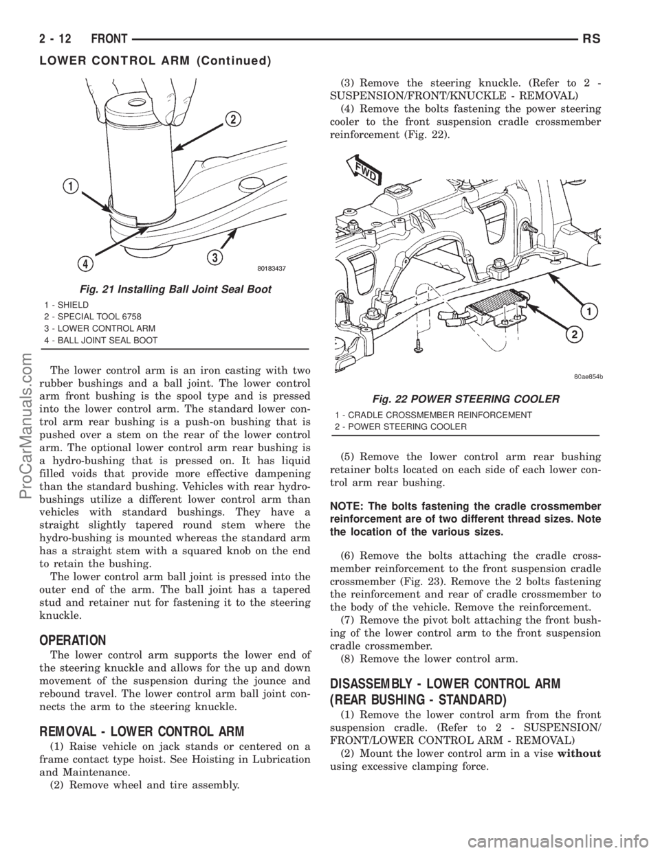
reinforcement (Fig. 22).
(5) Remove the lower control arm rear bushing
retainer bolts located on each side of each lower con-
trol arm rear bushing.
NOTE: The bolts fastening the cradle crossmember
reinforcement are of two different thread sizes. Note
the location of the various sizes.
(6) Remove the bolts attaching the cradle cross-
member reinforcement to the front suspension cradle
crossmember (Fig. 23). Remove the 2 bolts fastening
the reinforcement and rear of cradle crossmember to
the body of the vehicle. Remove the reinforcement.
(7) Remove the pivot bolt attaching the front bush-
ing of the lower control arm to the front suspension
cradle crossmember.
(8) Remove the lower control arm.
DISASSEMBLY - LOWER CONTROL ARM
(REAR BUSHING - STANDARD)
(1) Remove the lower control arm from the front
suspension cradle. (Refer to 2 - SUSPENSION/
FRONT/LOWER CONTROL ARM - REMOVAL)
(2) Mount the lower control arm in a visewithout
using excessive clamping force.
Fig. 21 Installing Ball Joint Seal Boot
1 - SHIELD
2 - SPECIAL TOOL 6758
3 - LOWER CONTROL ARM
4 - BALL JOINT SEAL BOOT
Fig. 22 POWER STEERING COOLER
1 - CRADLE CROSSMEMBER REINFORCEMENT
2 - POWER STEERING COOLER
2 - 12 FRONTRS
LOWER CONTROL ARM (Continued)
ProCarManuals.com
Page 65 of 2321
(10) Install the wheel and tire assembly. Install
and tighten the wheel mounting stud nuts in proper
sequence until all nuts are torqued to half specifica-
tion. Then repeat the tightening sequence to the full
specified torque of 135 N´m (100 ft. lbs.).
(11) Raise vehicle, remove jack stands and lower
vehicle to the ground.
(12) Perform front wheel alignment as necessary.
(Refer to 2 - SUSPENSION/WHEEL ALIGNMENT -
STANDARD PROCEDURE)
STABILIZER BAR
DESCRIPTION
The stabilizer bar interconnects both front struts of
the vehicle and is attached to the front crossmember
(Fig. 1) .
Attachment of the stabilizer bar to the front cross-
member is through 2 rubber-isolator cushion bush-
ings and retainers. A double ball jointed stabilizer
bar link is used to attach each end of the stabilizer
bar to the front strut assemblies. All parts of the sta-
bilizer bar are replaceable as individual components.
The stabilizer bar to front crossmember cushion
bushings are split for easy removal and installation.
The split in the bushings should be positioned toward
the rear of the vehicle, with the square corner facing
down, when the stabilizer bar is installed.
OPERATION
Jounce and rebound movements affecting one
wheel are partially transmitted to the opposite wheel
of the vehicle through the stabilizer bar. This helpsto minimize the body roll of the vehicle during sus-
pension movement.
Connecting the stabilizer bar links to the strut
assemblies helps reduce the fore-and-aft rate of the
stabilizer bar from the rest of the front suspension.
REMOVAL - STABILIZER BAR
(1) Raise vehicle on jack stands or centered on a
frame contact type hoist. See Hoisting in Lubrication
and Maintenance.
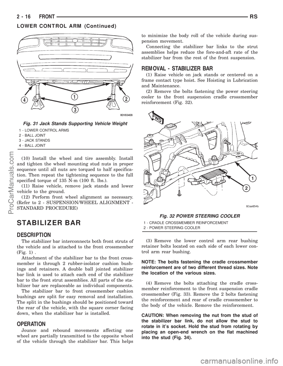
(2) Remove the bolts fastening the power steering
cooler to the front suspension cradle crossmember
reinforcement (Fig. 32).
(3) Remove the lower control arm rear bushing
retainer bolts located on each side of each lower con-
trol arm rear bushing.
NOTE: The bolts fastening the cradle crossmember
reinforcement are of two different thread sizes. Note
the location of the various sizes.
(4) Remove the bolts attaching the cradle cross-
member reinforcement to the front suspension cradle
crossmember (Fig. 33). Remove the 2 bolts fastening
the reinforcement and rear of cradle crossmember to
the body of the vehicle. Remove the reinforcement.
CAUTION: When removing the nut from the stud of
the stabilizer bar link, do not allow the stud to
rotate in it's socket. Hold the stud from rotating by
placing an open-end wrench on the flat machined
into the stud (Fig. 34).
Fig. 31 Jack Stands Supporting Vehicle Weight
1 - LOWER CONTROL ARMS
2 - BALL JOINT
3 - JACK STANDS
4 - BALL JOINT
Fig. 32 POWER STEERING COOLER
1 - CRADLE CROSSMEMBER REINFORCEMENT
2 - POWER STEERING COOLER
2 - 16 FRONTRS
LOWER CONTROL ARM (Continued)
ProCarManuals.com
Page 74 of 2321
(1) Install strut assembly into strut tower, aligning
and installing the 3 studs on the upper strut mount
into the holes in shock tower. Install the 3 upper
strut mount attaching nut/washer assemblies (Fig.
44). Then using a crow foot. tighten the 3 attaching
nuts to a torque of 28 N´m (250 in. lbs.).
CAUTION: The steering knuckle to strut assembly
attaching bolts are serrated and must not be turned
during installation. Install nuts while holding bolts
stationary in the steering knuckles.
NOTE: The strut clevis-to-steering knuckle bolts are
installed differently on each side of the vehicle. Left
hand side bolts are to be installed from vehicle rear
to front. Right side bolts are to be installed from
vehicle front to rear.
(2) Align strut assembly with steering knuckle.
Position arm of steering knuckle into strut assembly
clevis bracket. Align the strut assembly clevis
bracket mounting holes with the steering knuckle
mounting holes. Install the 2 strut assembly to steer-
ing knuckle attaching bolts (Fig. 43).If strut assem-
bly is attached to steering knuckle using a cam
bolt, the cam bolt must be installed in the lower
slotted hole on strut clevis bracket.Tighten the
strut clevis-to-steering knuckle attaching bolts to atorque of 81 N´m (60 ft. lbs.) plus an additional 1/4
(90É) turn after specified torque is met.
(3) Install the stabilizer bar link mounting stud
through the bracket on the strut assembly (Fig. 42).
CAUTION: When installing the nut on the mounting
stud of the stabilizer bar link, do not allow the stud
to rotate in it's socket. Hold the stud from rotating
by placing an open-end wrench on the flat
machined into the stud (Fig. 42).
(4) Hand thread the nut on the end of the stabi-
lizer bar link stud. Hold the stud from turning by
placing an open-end wrench on the flat machined
into the link's mounting stud, then tighten the nut
while holding the wrench in place (Fig. 42). Tighten
the nut to a torque of 88 N´m (65 ft. lbs.).
(5) Install the hydraulic brake hose and speed sen-
sor cable routing brackets on the strut assembly
brackets (Fig. 41). Tighten the routing bracket
attaching bolts to a torque of 13 N´m (10 ft. lbs.).
(6) Install the wheel/tire assembly on the vehicle.
(7) Install and tighten the wheel mounting stud
nuts in proper sequence until all nuts are torqued to
half specification. Then repeat the tightening
sequence to the full specified torque of 135 N´m (100
ft. lbs.).
RSFRONT2-25
STRUT (Continued)
ProCarManuals.com
Page 76 of 2321
SPECIFICATIONS
REAR SUSPENSION FASTENER TORQUE
DESCRIPTION N´mFt.
Lbs.In.
Lbs.
Hub And Bearing Mounting
Bolts129 95 Ð
Hub And Bearing Axle Hub Nut 244 180 Ð
Jounce Bumper Mounting Bolt 33 24 290
Leaf Spring Front Mount-To-
Body Bolts61 45 Ð
Leaf Spring Front Pivot Bolt 156 115 Ð
Leaf Spring Plate-To-Axle Bolts 102 75 Ð
Leaf Spring Rear Mount-To-
Body Bolts61 45 Ð
Leaf Spring Shackle Plate Nuts 61 45 Ð
Shock Absorber Mounting Bolts 102 75 Ð
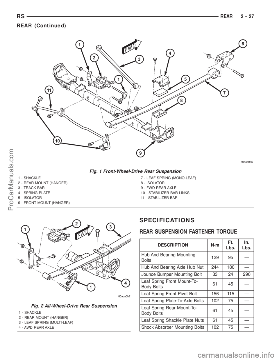
Fig. 1 Front-Wheel-Drive Rear Suspension
1 - SHACKLE
2 - REAR MOUNT (HANGER)
3 - TRACK BAR
4 - SPRING PLATE
5 - ISOLATOR
6 - FRONT MOUNT (HANGER)7 - LEAF SPRING (MONO-LEAF)
8 - ISOLATOR
9 - FWD REAR AXLE
10 - STABILIZER BAR LINKS
11 - STABILIZER BAR
Fig. 2 All-Wheel-Drive Rear Suspension
1 - SHACKLE
2 - REAR MOUNT (HANGER)
3 - LEAF SPRING (MULTI-LEAF)
4 - AWD REAR AXLE
RSREAR2-27
REAR (Continued)
ProCarManuals.com
Page 77 of 2321
DESCRIPTION N´mFt.
Lbs.In.
Lbs.
Stabilizer Bar Bushing Retainer
Bolts61 45 Ð
Stabilizer Bar Link Nuts 61 45 Ð
Stabilizer Bar Link Frame
Bracket Mounting Bolts61 45 Ð
Track Bar Bracket-To-Body
Mount Bolts61 45 Ð
Track Bar Pivot Bolts 95 70 Ð
Wheel Mounting (Lug) Nut 135 100 Ð
SPECIAL TOOLS
REAR SUSPENSION
BUSHINGS
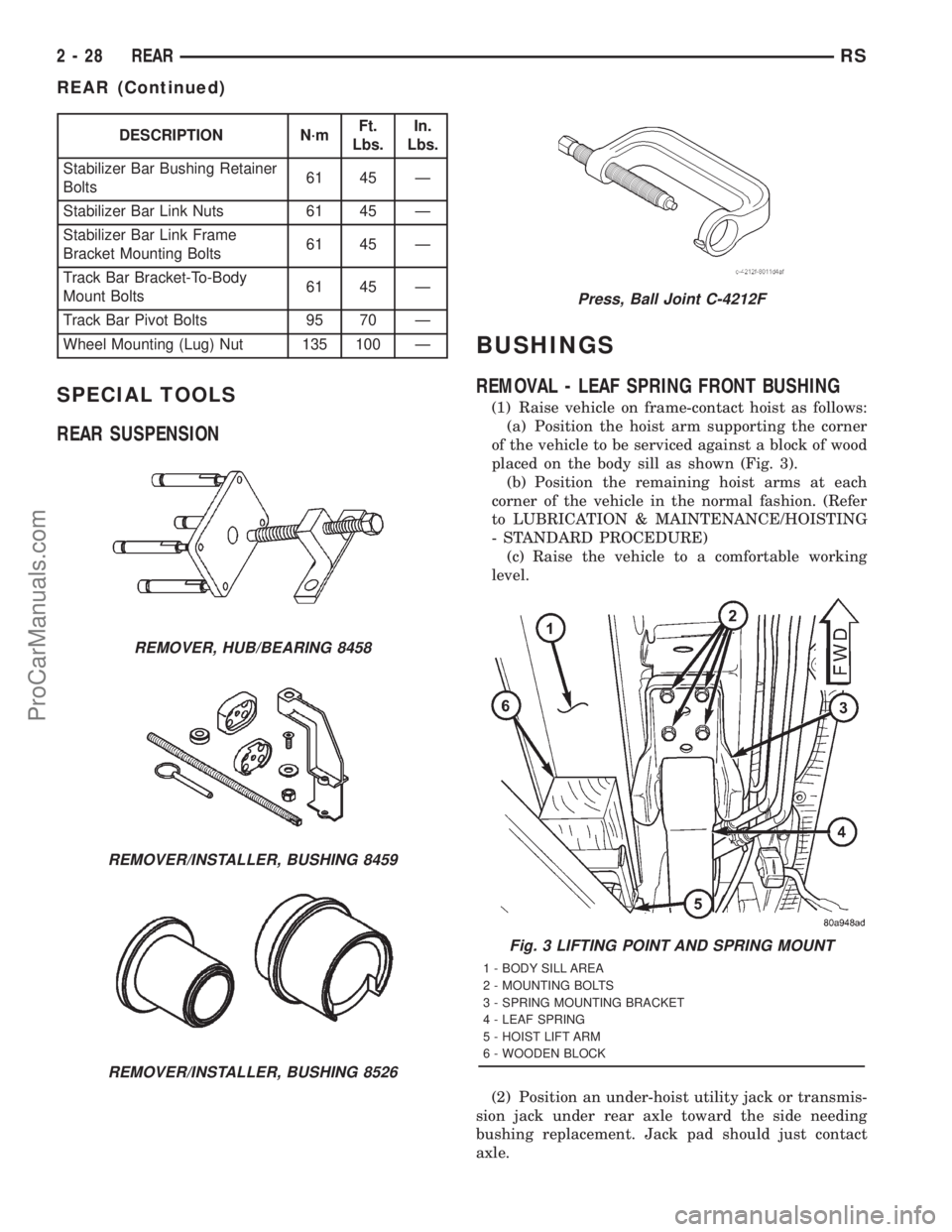
REMOVAL - LEAF SPRING FRONT BUSHING
(1) Raise vehicle on frame-contact hoist as follows:
(a) Position the hoist arm supporting the corner
of the vehicle to be serviced against a block of wood
placed on the body sill as shown (Fig. 3).
(b) Position the remaining hoist arms at each
corner of the vehicle in the normal fashion. (Refer
to LUBRICATION & MAINTENANCE/HOISTING
- STANDARD PROCEDURE)
(c) Raise the vehicle to a comfortable working
level.
(2) Position an under-hoist utility jack or transmis-
sion jack under rear axle toward the side needing
bushing replacement. Jack pad should just contact
axle.
REMOVER, HUB/BEARING 8458
REMOVER/INSTALLER, BUSHING 8459
REMOVER/INSTALLER, BUSHING 8526
Press, Ball Joint C-4212F
Fig. 3 LIFTING POINT AND SPRING MOUNT
1 - BODY SILL AREA
2 - MOUNTING BOLTS
3 - SPRING MOUNTING BRACKET
4 - LEAF SPRING
5 - HOIST LIFT ARM
6 - WOODEN BLOCK
2 - 28 REARRS
REAR (Continued)
ProCarManuals.com
Page 79 of 2321

body, Install the mounting bolts (Fig. 3). Tighten the
four mounting bolts to 61 N´m (45 ft. lbs.) torque.
(9) Raise or lower the jack until shock absorber
lower eye aligns with threads in axle housing. Install
shock absorber lower mounting bolt. Do not fully
tighten bolt at this time.
(10) Lower the vehicle and remove hoist arms and
block of wood from under vehicle.
(11) Tighten the spring front pivot bolt to 156 N´m
(115 ft. lbs.) torque.
(12) Tighten the lower shock absorber mounting
bolt to 102 N´m (75 ft. lbs.) torque.
HUB / BEARING
DESCRIPTION
The rear wheel bearing and rear wheel hub of this
vehicle are a one-piece sealed unit, or hub and bear-
ing unit type assembly. The hub and bearing is
mounted to the center of the rear axle using 4
mounting bolts. It has five wheel mounting studs on
the hub flange.
All-Wheel-Drive vehicles have a hub and bearing
unit with a splined hole in the center of the hub for
rear driveshaft stub axle acceptance.Front-Wheel-Drive vehicles with antilock brakes
have an internally mounted wheel speed sensor and
tone wheel. This hub and bearing can be identified
by the rounded cap and molded in connector on the
rear of the assembly (Fig. 7). The sensor and tone
wheel cannot be serviced separately from the hub
and bearing.
OPERATION
The hub and bearing has internal bearings that
allow the hub to rotate with the tire and wheel
assembly (and driveshaft on All-Wheel-Drive vehi-
cles). The five wheel mounting studs mount the tire
and wheel assembly, and disc brake rotor to the vehi-
cle.
On All-Wheel-Drive vehicles, the splined mating of
the driveshaft stub axle and hub allows the drive-
shaft to rotate with the hub and wheel.
Front-Wheel-Drive vehicles equipped with antilock
brakes have a wheel speed sensor and tone wheel
mounted to the rear of the hub and bearing. The tone
wheel rotates with the hub which is sensed by the
wheel speed sensor.
DIAGNOSIS AND TESTING - HUB AND
BEARING (REAR)
The bearing contained in the hub and bearing
assembly will produce noise and vibration when worn
or damaged. The noise will generally change when
the bearings are loaded. A road test of the vehicle is
normally required to determine the location of a
worn or damaged bearing.
Find a smooth level road surface and bring the
vehicle up to a constant speed. When vehicle is at a
constant speed, swerve the vehicle back and forth
from the left and to the right. This will load and
Fig. 6 TOOL 8459 MOUNTED FOR BUSHING
INSTALLATION
1 - NUT
2 - WASHER
3 - BEARING
4 - LEAF SPRING EYE
5 - BUSHING
6 - INSTALLER PLATE (8459-3)
7 - PIN
8 - BODY (8459-1)
Fig. 7 HUB AND BEARING - FWD WITH ABS
2 - 30 REARRS
BUSHINGS (Continued)
ProCarManuals.com
Page 80 of 2321

unload the bearings and change the noise level.
When bearing damage is slight, the noise is usually
not noticeable at speeds above 48 km/h (30 mph).
REMOVAL - HUB AND BEARING
FRONT-WHEEL-DRIVE VEHICLES
(1) Raise vehicle. See Hoisting in Lubrication and
Maintenance.
(2) Remove wheel and tire.
(3) Remove brake drum or disc brake caliper and
rotor from hub and bearing. Refer to Brakes.
(4) If equipped with antilock brakes, perform the
following:
(a) Remove secondary (yellow) retaining clip at
rear of wheel speed sensor head (Fig. 8).
(b) Push up on metal retaining clip (Fig. 8) until
it bottoms. This will release wheel speed sensor
head from hub and bearing.
(c) While holding metal clip up, pull back on
wheel speed sensor head removing it from hub and
bearing.
(5) Remove the 4 bolts attaching the hub and bear-
ing to the rear axle.
CAUTION: Corrosion may occur between the hub
and bearing, and the axle. If this occurs the hub
and bearing will be difficult to remove from the
axle. If the hub and bearing will not come out of the
axle by pulling on it by hand, do not pound on the
hub and bearing to remove it from the axle. Damage
will occur. Use the following procedure.(6) If hub and bearing cannot be removed from the
axle by hand, use Remover, Special Tool 8458 (Fig. 9)
and following procedure to press the hub and bearing
out of the axle.
(a) Thread Threaded Guide Pins into hub and
bearing mounting bolt holes.
(b) Remove the two outboard spring plate bolts.
(c) Using the spring plate bolts, install the
Screw Mount, Special Tool 8458±2, as shown (Fig.
9).
(d) Place Push Plate, Special Tool 8458±1, on
ends of Threaded Guide Pins
(e) Place a dab of grease in dimple of Push
Plate.
(f) Tighten the Forcing Screw, Special Tool
8458±3, up against dimple in Push Plate and press
hub and bearing out of axle by continuing to
tighten screw.
(g) Remove the tool.
(h) Reinstall the two outboard spring plate bolts.
Tighten the bolts to 102 N´m (75 ft. lbs.) torque.
(7) Remove the hub/bearing from the rear axle and
brake support plate.
ALL-WHEEL-DRIVE VEHICLES
(1) Set the parking brake.The parking brake is
set to keep the hub and bearing, and axle shaft
from rotating when loosening the hub nut.
Fig. 8 SENSOR CONNECTOR AT HUB AND
BEARING
1 - SECONDARY SENSOR RETAINING CLIP
2 - METAL SENSOR RETAINING CLIP
3 - HUB AND BEARING
Fig. 9 REMOVAL USING SPECIAL TOOL 8458
1 - THREADED GUIDE PINS 8458-4
2 - HUB AND BEARING
3 - LEAF SPRING PLATE
4 - FORCING SCREW 8458-3
5 - SCREW MOUNT 8458-2
6 - PUSH PLATE 8458-1
RSREAR2-31
HUB / BEARING (Continued)
ProCarManuals.com
Page 81 of 2321

(2) Raise vehicle. See Hoisting in Lubrication And
Maintenance.
(3) Remove the wheel/tire assembly.
(4) Remove the cotter pin and nut retainer (Fig.
19) from the stub shaft of the outer C/V joint.
(5) Remove the spring washer (Fig. 18) from the
stub shaft of the outer C/V joint.
(6) Remove the hub nut and washer (Fig. 16) from
the stub shaft of the outer C/V joint.
(7) Remove the 6 bolts (Fig. 17) mounting the
driveshaft inner joint to the output shaft of the rear
drive line module.
(8) Remove the rear wheel speed sensor (Fig. 20)
from the rear hub/bearing.
(9) Release the parking brake.
(10) Remove the disc brake caliper to adapter
guide pin bolts (Fig. 15).
(11) Remove rear caliper from adapter using the
following procedure. First rotate rear of caliper up
from the adapter. Then pull the front of the caliper
and the outboard brake shoe anti-rattle clip out from
under the front abutment on the adapter (Fig. 14).
(12) Support caliper to prevent the weight of the
caliper from damaging the flexible brake hose (Fig.
10).
(13) Remove the rotor from the hub/bearing.
(14) Remove driveshaft from rear drive line mod-
ule and hub/bearing. Driveshaft is removed by first
compressing the inner joint on the driveshaft and
removing it from the drive line module. Then, slide
the outer joint of the driveshaft out of the hub/bear-
ing.(15) Remove the hub/bearing to axle mounting
bolts (Fig. 13).
CAUTION: Corrosion may occur between the hub/
bearing and the axle. If this occurs the hub/bearing
will be difficult to remove from the axle. If the hub/
bearing will not come out of the axle by pulling on
it by hand, do not pound on the hub/bearing to
remove it from the axle. Pounding on the hub/bear-
ing to remove it from the axle will damage the hub/
bearing. This damage will result in noise or failure
of the hub/bearing. To remove a hub/bearing which
is corroded to the axle, lightly tap the disc brake
caliper adapter using a soft faced hammer. This will
remove both the disc brake caliper adapter and
hub/bearing from the axle. The hub/bearing will
then need to be removed from the caliper adapter.
(16) Remove the hub/bearing from the axle. (Fig.
12).
(17) If the disc brake caliper adapter and hub/
bearing were removed as an assembly from the axle
and the hub/bearing cannot be removed from the
adapter by hand, use the following procedure to
remove it from the adapter. With a helper supporting
the caliper adapter in his hands, position Remover,
Special Tool 8214-1 on the cast housing of hub/bear-
ing (Fig. 11).Do not position special tool on
inner race of hub/bearing.Lightly strike Remover,
Special Tool 8214-1 with a hammer to remove the
hub/bearing from the caliper adapter.
Fig. 10 Correctly Supported Caliper
1 - WIRE
2 - CALIPER
3 - ADAPTER
4 - ROTOR
5 - INNER FENDER
Fig. 11 Hub/Bearing Removal From Caliper Adapter
1 - SPECIAL TOOL 8214-1
2 - PARK BRAKE CABLE
3 - DISC BRAKE CALIPER ADAPTER
4 - HUB/BEARING
2 - 32 REARRS
HUB / BEARING (Continued)
ProCarManuals.com