2001 DODGE TOWN AND COUNTRY warning
[x] Cancel search: warningPage 42 of 2321
LUBRICANTS AND GREASES
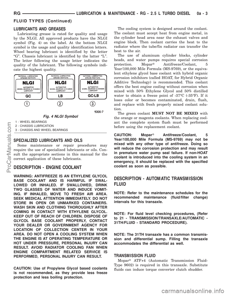
Lubricating grease is rated for quality and usage
by the NLGI. All approved products have the NLGI
symbol (Fig. 4) on the label. At the bottom NLGI
symbol is the usage and quality identification letters.
Wheel bearing lubricant is identified by the letter
ªGº. Chassis lubricant is identified by the latter ªLº.
The letter following the usage letter indicates the
quality of the lubricant. The following symbols indi-
cate the highest quality.
SPECIALIZED LUBRICANTS AND OILS
Some maintenance or repair procedures may
require the use of specialized lubricants or oils. Con-
sult the appropriate sections in this manual for the
correct application of these lubricants.
DESCRIPTION - ENGINE COOLANT
WARNING: ANTIFREEZE IS AN ETHYLENE GLYCOL
BASE COOLANT AND IS HARMFUL IF SWAL-
LOWED OR INHALED. IF SWALLOWED, DRINK
TWO GLASSES OF WATER AND INDUCE VOMIT-
ING. IF INHALED, MOVE TO FRESH AIR AREA.
SEEK MEDICAL ATTENTION IMMEDIATELY. DO NOT
STORE IN OPEN OR UNMARKED CONTAINERS.
WASH SKIN AND CLOTHING THOROUGHLY AFTER
COMING IN CONTACT WITH ETHYLENE GLYCOL.
KEEP OUT OF REACH OF CHILDREN. DISPOSE OF
GLYCOL BASE COOLANT PROPERLY, CONTACT
YOUR DEALER OR GOVERNMENT AGENCY FOR
LOCATION OF COLLECTION CENTER IN YOUR
AREA. DO NOT OPEN A COOLING SYSTEM WHEN
THE ENGINE IS AT OPERATING TEMPERATURE OR
HOT UNDER PRESSURE, PERSONAL INJURY CAN
RESULT. AVOID RADIATOR COOLING FAN WHEN
ENGINE COMPARTMENT RELATED SERVICE IS
PERFORMED, PERSONAL INJURY CAN RESULT.
CAUTION: Use of Propylene Glycol based coolants
is not recommended, as they provide less freeze
protection and less boiling protection.The cooling system is designed around the coolant.
The coolant must accept heat from engine metal, in
the cylinder head area near the exhaust valves and
engine block. Then coolant carries the heat to the
radiator where the tube/fin radiator can transfer the
heat to the air.
The use of aluminum cylinder blocks, cylinder
heads, and water pumps requires special corrosion
protection. MopartAntifreeze/Coolant, 5
Year/100,000 Mile Formula (MS-9769), or the equiva-
lent ethylene glycol base coolant with hybrid organic
corrosion inhibitors (called HOAT, for Hybrid Organic
Additive Technology) is recommended. This coolant
offers the best engine cooling without corrosion when
mixed with 50% Ethylene Glycol and 50% distilled
water to obtain a freeze point of -37ÉC (-35ÉF). If it
loses color or becomes contaminated, drain, flush,
and replace with fresh properly mixed coolant solu-
tion.
The green coolantMUST NOT BE MIXEDwith
the orange or magenta coolants. When replacing cool-
ant the complete system flush must be performed
before using the replacement coolant.
CAUTION: MoparTAntifreeze/Coolant, 5
Year/100,000 Mile Formula (MS-9769) may not be
mixed with any other type of antifreeze. Doing so
will reduce the corrosion protection and may result
in premature water pump seal failure. If non-HOAT
coolant is introduced into the cooling system in an
emergency, it should be replaced with the specified
coolant as soon as possible.DESCRIPTION - AUTOMATIC TRANSMISSION
FLUID
NOTE: Refer to the maintenance schedules for the
recommended maintenance (fluid/filter change)
intervals for this transaxle.
NOTE: For fluid level checking procedures, (Refer
to 21 - TRANSMISSION/TRANSAXLE/AUTOMATIC -
31TH/FLUID - STANDARD PROCEDURE).
NOTE: The 31TH transaxle has a common transmis-
sion and differential sump. Filling the transaxle
accommodates the differential as well.
TRANSMISSION FLUID
MopartATF+4 (Automatic Transmission Fluid-
Type 9602) is required in this transaxle. Substitute
fluids can induce torque converter clutch shudder.
Fig. 4 NLGI Symbol
1 - WHEEL BEARINGS
2 - CHASSIS LUBRICATION
3 - CHASSIS AND WHEEL BEARINGS
RGLUBRICATION & MAINTENANCE - RG - 2.5 L TURBO DIESEL0a-3
FLUID TYPES (Continued)
ProCarManuals.com
Page 43 of 2321
MopartATF+4 (Automatic Transmission Fluid-
Type 9602) when new is red in color. The ATF is dyed
red so it can be identified from other fluids used in
the vehicle such as engine oil or antifreeze. The red
color is not permanent and is not an indicator of fluid
condition. As the vehicle is driven, the ATF will begin
to look darker in color and may eventually become
brown.This is normal.A dark brown/black fluid
accompanied with a burnt odor and/or deterioration
in shift quality may indicate fluid deterioration or
transmission component failure.
FLUID ADDITIVES
DaimlerChrysler strongly recommends against the
addition of any fluids to the transmission, other than
those automatic transmission fluids listed above.
Exceptions to this policy are the use of special dyes
to aid in detecting fluid leaks.
Various ªspecialº additives and supplements exist
that claim to improve shift feel and/or quality. These
additives and others also claim to improve converter
clutch operation and inhibit overheating, oxidation,
varnish, and sludge. These claims have not been sup-
ported to the satisfaction of DaimlerChrysler and these
additivesmust not be used.
The use of transmission
ªsealersº should also be avoided, since they may
adversely affect the integrity of transmission seals.
DESCRIPTION - FUEL REQUIREMENTS -
DIESEL ENGINE
WARNING: DO NOT USE ALCOHOL OR GASOLINE
AS A FUEL BLENDING AGENT. THEY CAN BE
UNSTABLE UNDER CERTAIN CONDITIONS AND
HAZARDOUS OR EXPLOSIVE WHEN MIXED WITH
DIESEL FUEL.
Use good quality diesel fuel from a reputable sup-
plier. For most year-round service, number 2 diesel
fuel meeting ASTM specification D-975 will provide
good performance. If the vehicle is exposed to
extreme cold (below -18ÉC/0ÉF) or is required to oper-
ate at colder than normal conditions for prolonged
periods, use climatize No. 2 diesel fuel or dilute the
No. 2 diesel fuel with 50% No. 1 diesel fuel. This will
provide better protection from fuel gelling or wax
plugging of the fuel filters.
Diesel fuel is seldom completely free of water. To
prevent fuel system trouble, including fuel line freez-
ing in winter, drain the accumulated water from the
fuel/water separator using the fuel/water separator
drain provided. If you buy good quality fuel and follow
the cold weather advice above, fuel conditioners should
not be required in your vehicle. If available in your
area, a high cetane ªpremiumº diesel fuel may offer
improved cold starting and warm up performance.
DESCRIPTION - DIESEL ENGINE OIL
API SERVICE GRADE CERTIFIED
WARNING: NEW OR USED ENGINE OIL CAN BE
IRRITATING TO THE SKIN. AVOID PROLONGED OR
REPEATED SKIN CONTACT WITH ENGINE OIL.
CONTAMINANTS IN USED ENGINE OIL, CAUSED BY
INTERNAL COMBUSTION, CAN BE HAZARDOUS TO
YOUR HEALTH. THOROUGHLY WASH EXPOSED
SKIN WITH SOAP AND WATER. DO NOT WASH
SKIN WITH GASOLINE, DIESEL FUEL, THINNER, OR
SOLVENTS, HEALTH PROBLEMS CAN RESULT. DO
NOT POLLUTE, DISPOSE OF USED ENGINE OIL
PROPERLY. CONTACT YOUR DEALER OR GOVERN-
MENT AGENCY FOR LOCATION OF COLLECTION
CENTER IN YOUR AREA.
Standard engine oil identification notations have
been adopted to aid in the proper selection of engine
oil. The identifying notations are located on the label
of engine oil plastic bottles and the top of engine oil
cans.
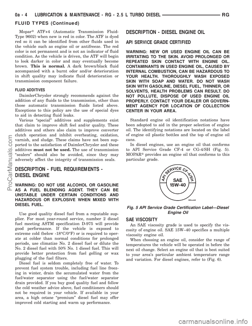
In diesel engines, use an engine oil that conforms
to API Service Grade CF-4 or CG-4/SH (Fig. 5).
MOPARtprovides an engine oil that conforms to this
particular grade.
SAE VISCOSITY
An SAE viscosity grade is used to specify the vis-
cosity of engine oil. SAE 15W±40 specifies a multiple
viscosity engine oil.
When choosing an engine oil, consider the range of
temperatures the vehicle will be operated in before the
next oil change. Select an engine oil that is best suited
to your area's particular ambient temperature range
and variation. For diesel engines, refer to (Fig. 6).
Fig. 5 API Service Grade Certification LabelÐDiesel
Engine Oil
0a - 4 LUBRICATION & MAINTENANCE - RG - 2.5 L TURBO DIESELRG
FLUID TYPES (Continued)
ProCarManuals.com
Page 46 of 2321

²Inspect air filter element.
²Replace fuel filter/water separator element. (2)
²Check alignment.
140 000 km (86 000 Miles)
²Change engine oil. (1)
²Replace engine oil filter.
²Replace air filter element.
150 000 km (93 000 Miles)
²Change engine oil. (1)
²Replace engine oil filter.
²Inspect air filter element.
²Replace fuel filter/water separator element. (2)
²Check alignment.
160 000 km (100 000 Miles)
²Change engine oil. (1)
²Replace engine oil filter.
²Replace air filter element.
²Flush and replace engine coolant. (3)
²Change oil every 12 months regardless of mile-
age.
²The fuel filter/water separator element should
be replaced once a year if the vehicle is driven less
than 20 000 km annually or if power loss from fuel
starvation is detected.
²
Flush and replace engine coolant every 60 months
even if the vehicle is driven less than 160 000 km.
²Change manual transaxle fluid.
HOISTING
STANDARD PROCEDURE - HOISTING
Refer to Owner's Manual provided with vehicle for
proper emergency jacking procedures.
WARNING: THE HOISTING AND JACK LIFTING
POINTS PROVIDED ARE FOR A COMPLETE VEHI-
CLE. WHEN THE ENGINE OR REAR SUSPENSION
IS REMOVED FROM A VEHICLE, THE CENTER OF
GRAVITY IS ALTERED MAKING SOME HOISTING
CONDITIONS UNSTABLE. PROPERLY SUPPORT OR
SECURE VEHICLE TO HOISTING DEVICE WHEN
THESE CONDITIONS EXIST.
CAUTION: Do not position hoisting device on any
suspension component, including the front suspen-
sion crossmember, the rear leaf springs, and the
rear axle. Do not hoist on the front and rear
bumpers, the lower liftgate crossmember, the lower
radiator crossmember, the down standing flanges
on the sill or the front engine mount.
FOR PROPER HOIST PLACEMENT REFER
TO (Fig. 7).The hoisting points are identified by S.A.E.
inverted triangle hoisting symbols (Fig. 7). The front
hoisting points are at the bottom of the font rail
below the hoisting symbol approximately 250mm
behind the front suspension crossmember. When
using outboard lift hoists, verify that the hoist lift
pads have been properly adjusted to eliminate con-
tact between the hoist arm and the down standing
flange on the sill. The rear hoisting points are the
leaf spring front mounting brackets. The hoist pad
must be positioned to pick up the flanges on the
bracket, not the leaf spring.
When servicing the leaf springs or the leaf spring
mounting brackets, special provisions are required to
support the rear of the vehicle. Position the rear
hoist pads under the horizontal surface on the bot-
tom of the sill, inboard adjacent to the flange and
centered fore/aft between the jacking indicator tabs
on the lower flange.DO NOT HOIST ON THE
FLANGE.Place a soft pad between the hoist and the
painted surface on the sill to avoid scratching the fin-
ish.
Fig. 7 HOISTING AND JACKING POINTS
1 - Drive On Lift
2 - Frame Contact Lift (Single Post)
Chassis Lift (Non-Axle Dual Post)
Outboard Lift (Dual Post)
Floor Jack
3 - S.A.E. Hoisting Symbols
RGLUBRICATION & MAINTENANCE - RG - 2.5 L TURBO DIESEL0a-7
MAINTENANCE SCHEDULES (Continued)
ProCarManuals.com
Page 47 of 2321
JUMP STARTING
STANDARD PROCEDURE - JUMP STARTING
(1) Raise hood on disabled vehicle and visually
inspect engine compartment for:
²Battery cable clamp condition, clean if necessary.
²Frozen battery.
²Yellow or bright color test indicator, if equipped.
²Low battery fluid level.
²Generator drive belt condition and tension.
²Fuel fumes or leakage, correct if necessary.
CAUTION: If the cause of starting problem on dis-
abled vehicle is severe, damage to booster vehicle
charging system can result.
(2) When using another vehicle as a booster
source, park the booster vehicle within cable reach.
Turn off all accessories, set the parking brake, place
the automatic transmission in PARK or the manual
transmission in NEUTRAL and turn the ignition
OFF.
(3)
On disabled vehicle, place gear selector in park
or neutral and set park brake. Turn off all accessories.
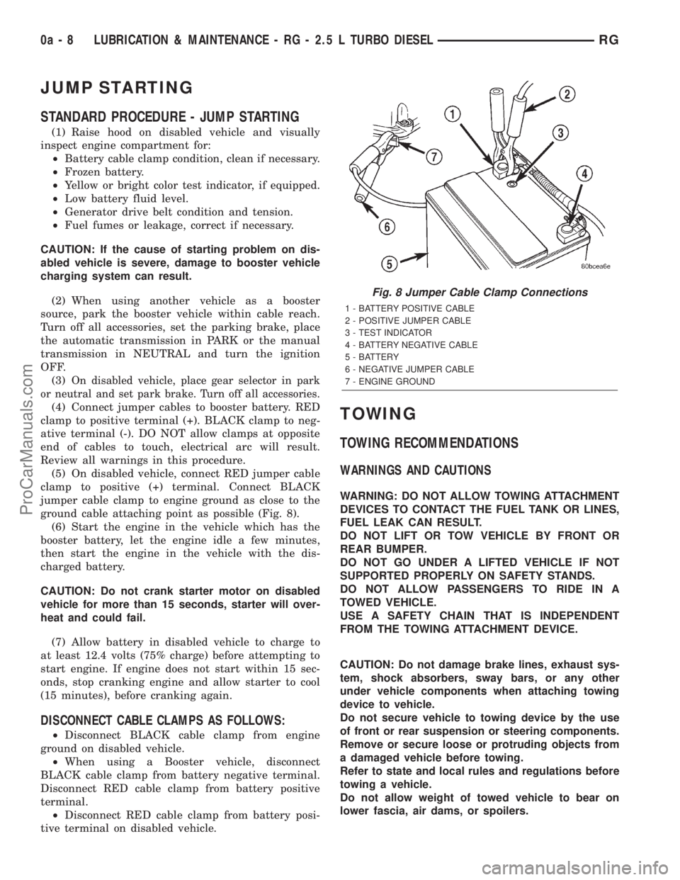
(4) Connect jumper cables to booster battery. RED
clamp to positive terminal (+). BLACK clamp to neg-
ative terminal (-). DO NOT allow clamps at opposite
end of cables to touch, electrical arc will result.
Review all warnings in this procedure.
(5) On disabled vehicle, connect RED jumper cable
clamp to positive (+) terminal. Connect BLACK
jumper cable clamp to engine ground as close to the
ground cable attaching point as possible (Fig. 8).
(6) Start the engine in the vehicle which has the
booster battery, let the engine idle a few minutes,
then start the engine in the vehicle with the dis-
charged battery.
CAUTION: Do not crank starter motor on disabled
vehicle for more than 15 seconds, starter will over-
heat and could fail.
(7) Allow battery in disabled vehicle to charge to
at least 12.4 volts (75% charge) before attempting to
start engine. If engine does not start within 15 sec-
onds, stop cranking engine and allow starter to cool
(15 minutes), before cranking again.
DISCONNECT CABLE CLAMPS AS FOLLOWS:
²Disconnect BLACK cable clamp from engine
ground on disabled vehicle.
²When using a Booster vehicle, disconnect
BLACK cable clamp from battery negative terminal.
Disconnect RED cable clamp from battery positive
terminal.
²Disconnect RED cable clamp from battery posi-
tive terminal on disabled vehicle.
TOWING
TOWING RECOMMENDATIONS
WARNINGS AND CAUTIONS
WARNING: DO NOT ALLOW TOWING ATTACHMENT
DEVICES TO CONTACT THE FUEL TANK OR LINES,
FUEL LEAK CAN RESULT.
DO NOT LIFT OR TOW VEHICLE BY FRONT OR
REAR BUMPER.
DO NOT GO UNDER A LIFTED VEHICLE IF NOT
SUPPORTED PROPERLY ON SAFETY STANDS.
DO NOT ALLOW PASSENGERS TO RIDE IN A
TOWED VEHICLE.
USE A SAFETY CHAIN THAT IS INDEPENDENT
FROM THE TOWING ATTACHMENT DEVICE.
CAUTION: Do not damage brake lines, exhaust sys-
tem, shock absorbers, sway bars, or any other
under vehicle components when attaching towing
device to vehicle.
Do not secure vehicle to towing device by the use
of front or rear suspension or steering components.
Remove or secure loose or protruding objects from
a damaged vehicle before towing.
Refer to state and local rules and regulations before
towing a vehicle.
Do not allow weight of towed vehicle to bear on
lower fascia, air dams, or spoilers.
Fig. 8 Jumper Cable Clamp Connections
1 - BATTERY POSITIVE CABLE
2 - POSITIVE JUMPER CABLE
3 - TEST INDICATOR
4 - BATTERY NEGATIVE CABLE
5 - BATTERY
6 - NEGATIVE JUMPER CABLE
7 - ENGINE GROUND
0a - 8 LUBRICATION & MAINTENANCE - RG - 2.5 L TURBO DIESELRG
ProCarManuals.com
Page 69 of 2321

arately for each corner or side of the vehicle depend-
ing on optional equipment and type of vehicle
service. If the coil springs require replacement, be
sure that the springs are replaced with springs meet-
ing the correct load rating and spring rate for the
vehicle and its specific options.
OPERATION - STRUT ASSEMBLY
The strut assembly cushions the ride of the vehicle,
controlling vibration, along with jounce and rebound
of the suspension.
The coil spring controls ride quality and maintains
proper ride height.
The spring isolators isolate the coil spring at the
top and bottom from coming into metal-to-metal con-
tact with the upper seat and strut.
The jounce bumper limits suspension travel and
metal-to-metal contact under full jounce condition.
The strut dampens jounce and rebound motions of
the coil spring and suspension.
During steering maneuvers, the strut assembly
(through a pivot bearing in the upper strut mount)
and steering knuckle (through the lower ball joint)
turn as an assembly.
DIAGNOSIS AND TESTING - STRUT ASSEMBLY
(FRONT)
(1) Inspect for damaged or broken coil springs
(Fig. 39).
(2) Inspect for torn or damaged strut assembly
dust boots (Fig. 39).
(3) Inspect the coil spring isolator on the lower
spring seat for any signs of damage or deterioration.
(4) Lift dust boot (Fig. 40) and inspect strut
assembly for evidence of fluid running from the
upper end of fluid reservoir. (Actual leakage will be a
stream of fluid running down the side and dripping
off lower end of unit). A slight amount of seepage
between the strut rod and strut shaft seal is not
unusual and does not affect performance of the strut
assembly (Fig. 40). Also inspect jounce bumpers for
signs of damage or deterioration.
REMOVAL - STRUT ASSEMBLY
WARNING: DO NOT REMOVE THE NUT FROM THE
STRUT ROD WHILE STRUT ASSEMBLY IS
INSTALLED IN VEHICLE, OR BEFORE STRUT
ASSEMBLY SPRING IS COMPRESSED.
(1) Raise the vehicle. See Hoisting in Lubrication
and Maintenance.
(2) Remove the wheel and tire assembly from loca-
tion on front of vehicle requiring strut removal.(3) If both strut assemblies are to be removed,
mark the strut assemblies right or left according to
which side of the vehicle they were removed from.
(4) Remove the hydraulic brake hose routing
bracket and the speed sensor cable routing bracket
from the strut damper brackets (Fig. 41).
Fig. 40 Strut Assembly Leakage Inspection (Typical)
1 - DUST BOOT
2 - STRUT SHAFT
3 - STRUT FLUID RESERVOIR
4 - INSPECT THIS AREA FOR EVIDENCE OF EXCESSIVE FLUID
LEAKAGE
Fig. 41 Brake Hose And Speed Sensor Cable
Routing
1 - STRUT DAMPER
2 - WHEEL SPEED SENSOR CABLE
3 - ROUTING BRACKET
4 - HYDRAULIC BRAKE HOSE
5 - ATTACHING BOLT
6 - ROUTING BRACKET
2 - 20 FRONTRS
STRUT (Continued)
ProCarManuals.com
Page 70 of 2321
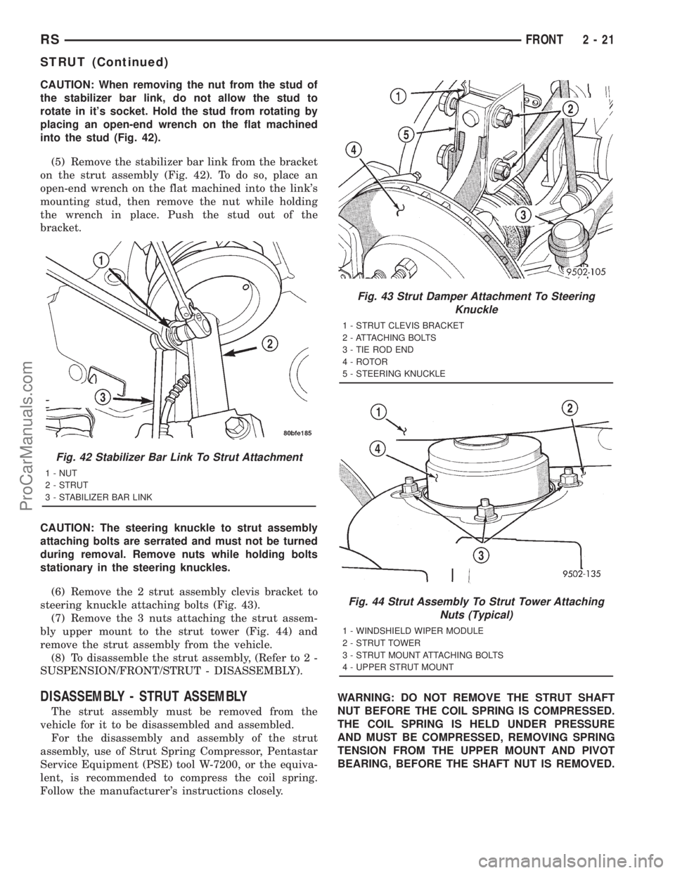
CAUTION: When removing the nut from the stud of
the stabilizer bar link, do not allow the stud to
rotate in it's socket. Hold the stud from rotating by
placing an open-end wrench on the flat machined
into the stud (Fig. 42).
(5) Remove the stabilizer bar link from the bracket
on the strut assembly (Fig. 42). To do so, place an
open-end wrench on the flat machined into the link's
mounting stud, then remove the nut while holding
the wrench in place. Push the stud out of the
bracket.
CAUTION: The steering knuckle to strut assembly
attaching bolts are serrated and must not be turned
during removal. Remove nuts while holding bolts
stationary in the steering knuckles.
(6) Remove the 2 strut assembly clevis bracket to
steering knuckle attaching bolts (Fig. 43).
(7) Remove the 3 nuts attaching the strut assem-
bly upper mount to the strut tower (Fig. 44) and
remove the strut assembly from the vehicle.
(8) To disassemble the strut assembly, (Refer to 2 -
SUSPENSION/FRONT/STRUT - DISASSEMBLY).
DISASSEMBLY - STRUT ASSEMBLY
The strut assembly must be removed from the
vehicle for it to be disassembled and assembled.
For the disassembly and assembly of the strut
assembly, use of Strut Spring Compressor, Pentastar
Service Equipment (PSE) tool W-7200, or the equiva-
lent, is recommended to compress the coil spring.
Follow the manufacturer's instructions closely.WARNING: DO NOT REMOVE THE STRUT SHAFT
NUT BEFORE THE COIL SPRING IS COMPRESSED.
THE COIL SPRING IS HELD UNDER PRESSURE
AND MUST BE COMPRESSED, REMOVING SPRING
TENSION FROM THE UPPER MOUNT AND PIVOT
BEARING, BEFORE THE SHAFT NUT IS REMOVED.
Fig. 42 Stabilizer Bar Link To Strut Attachment
1 - NUT
2 - STRUT
3 - STABILIZER BAR LINK
Fig. 43 Strut Damper Attachment To Steering
Knuckle
1 - STRUT CLEVIS BRACKET
2 - ATTACHING BOLTS
3 - TIE ROD END
4 - ROTOR
5 - STEERING KNUCKLE
Fig. 44 Strut Assembly To Strut Tower Attaching
Nuts (Typical)
1 - WINDSHIELD WIPER MODULE
2 - STRUT TOWER
3 - STRUT MOUNT ATTACHING BOLTS
4 - UPPER STRUT MOUNT
RSFRONT2-21
STRUT (Continued)
ProCarManuals.com
Page 133 of 2321
PROPELLER SHAFT
TABLE OF CONTENTS
page page
PROPELLER SHAFT
DESCRIPTION...........................24
OPERATION.............................24REMOVAL..............................24
INSTALLATION...........................24
SPECIFICATIONS........................25
PROPELLER SHAFT
DESCRIPTION
WARNING: Due to propeller shaft imbalance con-
cerns, the propeller shaft can only be serviced as
an assembly.
AWD models utilize a ªtwo-pieceº propeller shaft
(Fig. 1) to transmit power to the rear driveline mod-
ule assembly. This two-piece design consists of:
²Front and rear shaft segments.
²Plunging center CV joint
²Center support bearing
²Rubber coupler at driveline module flange
The front shaft segment utilizes a CV joint at the
power transfer unit connection, and a plunging CV
joint at the center bearing location.
The rear shaft segment utilizes a center support
bearing at the forward position, and a rubber coupler
at the driveline module flange.
OPERATION
The propeller shaft (Fig. 1) is used to transmit
torque from the transaxle power transfer unit (PTU)
to the rear driveline module of AWD equipped mod-
els.
The propeller shaft front half utilizes a CV joint at
the PTU flange, and a plunging CV joint at the cen-
ter bearing location. These joints are flexible, allow-
ing for torsional movement of the powertrain.
The propeller shaft rear half utilizes a center sup-
port bearing, which supports this two-piece assembly.
The bearing also stabilizes the rear shaft segment to
minimize axle wind-up. The rubber coupler at the
driveline module flange dampens out propeller shaft
torsional vibrations, as the driveline module it con-
nects to is fastened to the vehicle body.
REMOVAL
CAUTION: Propeller shaft removal is a two-man
operation. Never allow propeller shaft to hang whileconnected to power transfer unit (PTU) or rear driv-
eline module flanges. A helper is required.
(1) Make sure transaxle is in neutral (N). Using
chalk, mark propeller shaft flanges at PTU and rear
driveline module for installation reference.
(2) Remove six propeller shaft-to-power transfer
unit bolts.
(3) Have helper remove three propeller shaft rub-
ber coupler-to-driveline module bolts while he/she
supports rear shaft by hand.
(4) Remove center bearing support-to-crossmember
bolts, while supporting front shaft with two hands.
(5) Lower propeller shaft assembly to ground,
using care not to damage fore and aft flanges (Fig.
1).
INSTALLATION
CAUTION: Propeller shaft installation is a two-man
operation. Never allow propeller shaft to hang while
connected to power transfer unit (PTU) or rear driv-
eline module flanges. A helper is required.
(1) Make sure transaxle is in Neutral (N) position.
(2) Obtain a helper and lift propeller shaft assem-
bly into position (Fig. 1).
(3) While helper supports front half of shaft level
to underbody, align paint marks at driveline module
flange and install three propeller shaft rubber cou-
pler-to-rear driveline module bolts by hand. Do not
torque at this time.
(4) While helper supports front half of shaft level
to underbody, align chalk marks at PTU flange.
Install six propeller shaft-to-PTU flange bolts and
torque to 30 N´m (22 ft. lbs.). Torque bolts alternately
to ensure proper flange mating.
(5) Place center bearing into position. Install and
torque center bearing-to-crossmember bolts to 54
N´m (40 ft. lbs.).
(6) Torque propeller shaft rubber coupler-to-rear
driveline module assembly to 54 N´m (40 ft. lbs.).
3 - 24 PROPELLER SHAFTRS
ProCarManuals.com
Page 139 of 2321
DISASSEMBLY
WARNING: Differential is only to be serviced as an
assembly, and no disassembly is required.
(1) Remove six torque arm-to-differential case
bolts and remove torque arm assembly (Fig. 4).
(2) Remove input flange nut and washer using
Tool 6958 and a breaker bar (Fig. 5).(3) Remove input flange (Fig. 6).
(4) Remove input flange seal from overrunning
clutch housing using suitable screwdriver (Fig. 7).
(5) Remove four overrunning clutch housing-to-dif-
ferential assembly bolts (Fig. 8) and remove housing.
(6) Remove front bearing snap ring (Fig. 14).
(7) Remove front bearing (Fig. 14).
(8) Remove o-ring and washer from overrunning
clutch assembly (Fig. 14).
Fig. 4 Torque Arm Fasteners
1 - TORQUE ARM ASSEMBLY
2 - BOLT (SIX)
Fig. 5 Input Flange Nut
1 - INPUT FLANGE
2 - TOOL 6958
Fig. 6 Input Flange
1 - INPUT FLANGE/SHIELD
Fig. 7 Input Flange Seal Removal
1 - INPUT FLANGE SEAL
2 - SCREWDRIVER
3 - 30 REAR DRIVELINE MODULERS
REAR DRIVELINE MODULE (Continued)
ProCarManuals.com