2001 DODGE TOWN AND COUNTRY traction control
[x] Cancel search: traction controlPage 360 of 2321

OPERATION
The Body Control Module (BCM) is designed to
control and integrate many of the electronic features
and functions of the vehicle. The microprocessor-
based BCM hardware and software monitors many
hard wired switch and sensor inputs as well as those
resources it shares with other electronic modules in
the vehicle through its communication over the PCI
data bus network. The internal programming and all
of these inputs allow the BCM microprocessor to
determine the tasks it needs to perform and their
priorities, as well as both the standard and optional
features that it should provide. The BCM program-
ming then performs those tasks and provides those
features through both PCI data bus communication
with other electronic modules and through hard
wired low current outputs to a number of relays.
These relays provide the BCM with the ability to
control numerous high current accessory systems in
the vehicle.
The BCM monitors its own internal circuitry as
well as many of its input and output circuits, and
will store a Diagnostic Trouble Code (DTC) in elec-
tronic memory for any failure it detects. These DTCs
can be retrieved and diagnosed using a DRBIIItscan
tool. Refer to the appropriate diagnostic information.
REMOVAL
(1) Disconnect and isolate the battery negative
cable.
(2) Remove lower steering column cover and knee
blocker reinforcement.
(3) Disconnect two wire connectors from bottom of
Body Control Module (BCM)
(4) Remove bolts holding the BCM to the dash
panel mounting bracket.
(5) Remove the BCM from the mounting bracket.
INSTALLATION
(1) Install the BCM onto the mounting bracket.
(2) Install the bolts holding the BCM to dash
panel mounting bracket.
(3) Connect two wire connectors to the bottom of
the BCM.
(4) Install the lower steering column cover and
knee blocker reinforcement.
(5) Connect the battery negative cable.
CONTROLLER ANTILOCK
BRAKE
DESCRIPTION
The controller antilock brake (CAB) is a micropro-
cessor-based device which monitors the antilock
brake system (ABS) during normal braking and con-trols it when the vehicle is in an ABS stop. The CAB
is mounted to the HCU as part of the integrated con-
trol unit (ICU) (Fig. 1). The CAB uses a 24-way elec-
trical connector on the vehicle wiring harness. The
power source for the CAB is through the ignition
switch in the RUN or ON position. The CAB is on
the PCI bus.
OPERATION
The primary functions of the controller antilock
brake (CAB) are to:
²Monitor the antilock brake system for proper
operation.
²Detect wheel locking or wheel slipping tenden-
cies by monitoring the speed of all four wheels of the
vehicle.
²Control fluid modulation to the wheel brakes
while the system is in an ABS mode.
²Store diagnostic information.
²Provide communication to the DRBIIItscan tool
while in diagnostic mode.
²Illuminate the amber ABS warning indicator
lamp.
²(With traction control only) Illuminate the TRAC
ON lamp in the message center on the instrument
panel when a traction control event occurs.
²(with traction control only) Illuminate the TRAC
OFF lamp when the amber ABS warning indicator
lamp illuminates.
The CAB constantly monitors the antilock brake
system for proper operation. If the CAB detects a
fault, it will turn on the amber ABS warning indica-
tor lamp and disable the antilock braking system.
Fig. 1 INTEGRATED CONTROL UNIT (ICU)
1 - PUMP/MOTOR
2 - HCU
3 - PUMP/MOTOR CONNECTOR
4 - CAB
RSELECTRONIC CONTROL MODULES8E-3
BODY CONTROL MODULE (Continued)
ProCarManuals.com
Page 361 of 2321

The normal base braking system will remain opera-
tional.
NOTE: If the vehicle is equipped with traction con-
trol, the TRAC OFF lamp will illuminate anytime the
amber ABS warning indicator lamp illuminates.
The CAB continuously monitors the speed of each
wheel through the signals generated by the wheel
speed sensors to determine if any wheel is beginning
to lock. When a wheel locking tendency is detected,
the CAB commands the CAB command coils to actu-
ate. The coils then open and close the valves in the
HCU that modulate brake fluid pressure in some or
all of the hydraulic circuits. The CAB continues to
control pressure in individual hydraulic circuits until
a locking tendency is no longer present.
The CAB contains a self-diagnostic program that
monitors the antilock brake system for system faults.
When a fault is detected, the amber ABS warning
indicator lamp is turned on and the fault diagnostic
trouble code (DTC) is then stored in a diagnostic pro-
gram memory. These DTC's will remain in the CAB
memory even after the ignition has been turned off.
The DTC's can be read and cleared from the CAB
memory by a technician using the DRBIIItscan tool.
If not cleared with a DRBIIItscan tool, the fault
occurrence and DTC will be automatically cleared
from the CAB memory after the identical fault has
not been seen during the next 3,500 miles.
CAB INPUTS
²Wheel speed sensors (four)
²Brake lamp switch
²Ignition switch
²System and pump voltage
²Ground
²Traction control switch (if equipped)
²Diagnostic communication (PCI)
CAB OUTPUTS
²Amber ABS warning indicator lamp actuation
(via BUS)
²Instrument cluster (MIC) communication (PCI)
²Traction control lamps (if equipped)
²Diagnostic communication (PCI, via BUS)
REMOVAL
(1) Disconnect the battery cables.
(2) Remove the battery (Refer to 8 - ELECTRI-
CAL/BATTERY SYSTEM/BATTERY - REMOVAL).
(3) Disconnect the vacuum hose connector at the
tank built into the battery tray.
(4) Remove the screw securing the coolant filler
neck to the battery tray.
(5) Remove the battery tray (Refer to 8 - ELEC-
TRICAL/BATTERY SYSTEM/TRAY - REMOVAL).(6) Pull up on the CAB connector lock and discon-
nect the 24±way electrical connector and the pump/
motor connector from the CAB (Fig. 2)
(7) Remove the screws securing the CAB to the
vehicle (Fig. 3)
INSTALLATION
(1) Install screws to secure the CAB to the vehicle
(Fig. 3) Tighten the mounting screws to 2 N´m (17 in
lbs).
Fig. 2 CAB CONNECTOR LOCK
1 - CONNECTOR LOCK
2 - CAB
Fig. 3 CAB MOUNTING SCREWS
1 - HCU
2 - MOUNTING SCREWS
3 - CAB
8E - 4 ELECTRONIC CONTROL MODULESRS
CONTROLLER ANTILOCK BRAKE (Continued)
ProCarManuals.com
Page 460 of 2321

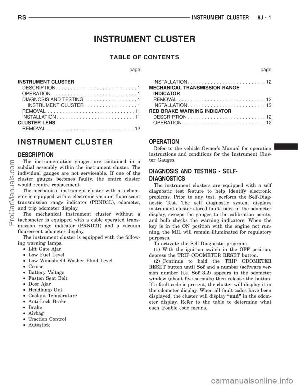
INSTRUMENT CLUSTER
TABLE OF CONTENTS
page page
INSTRUMENT CLUSTER
DESCRIPTION............................1
OPERATION.............................1
DIAGNOSIS AND TESTING..................1
INSTRUMENT CLUSTER..................1
REMOVAL..............................11
INSTALLATION...........................11
CLUSTER LENS
REMOVAL..............................12INSTALLATION...........................12
MECHANICAL TRANSMISSION RANGE
INDICATOR
REMOVAL..............................12
INSTALLATION...........................12
RED BRAKE WARNING INDICATOR
DESCRIPTION...........................12
OPERATION.............................12
INSTRUMENT CLUSTER
DESCRIPTION
The instrumentation gauges are contained in a
subdial assembly within the instrument cluster. The
individual gauges are not serviceable. If one of the
cluster gauges becomes faulty, the entire cluster
would require replacement.
The mechanical instrument cluster with a tachom-
eter is equipped with a electronic vacuum fluorescent
transmission range indicator (PRND3L), odometer,
and trip odometer display.
The mechanical instrument cluster without a
tachometer is equipped with a cable operated trans-
mission range indicator (PRND21) and a vacuum
flourescent odometer display.
The instrument cluster is equipped with the follow-
ing warning lamps.
²Lift Gate Ajar
²Low Fuel Level
²Low Windshield Washer Fluid Level
²Cruise
²Battery Voltage
²Fasten Seat Belt
²Door Ajar
²Headlamp Out
²Coolant Temperature
²Anti-Lock Brake
²Brake
²Airbag
²Traction Control
²Autostick
OPERATION
Refer to the vehicle Owner's Manual for operation
instructions and conditions for the Instrument Clus-
ter Gauges.
DIAGNOSIS AND TESTING - SELF-
DIAGNOSTICS
The instrument clusters are equipped with a self
diagnostic test feature to help identify electronic
problems. Prior to any test, perform the Self-Diag-
nostic Test. The self diagnostic system displays
instrument cluster stored fault codes in the odometer
display, sweeps the gauges to the calibration points,
and bulb checks the warning indicators. When the
key is in the ON position with the engine not run-
ning, the MIL will remain illuminated for regulatory
purposes.
To activate the Self-Diagnostic program:
(1) With the ignition switch in the OFF position,
depress the TRIP ODOMETER RESET button.
(2) Continue to hold the TRIP ODOMETER
RESET button untilSofand a number (software ver-
sion number (i.e.Sof 3.2) appears in the odometer
window (about five seconds) then release the button.
If a fault code is present, the cluster will display it in
the odometer display. When all fault codes have been
displayed, the cluster will displayªendºin the odom-
eter display. Refer to the table to determine what
each trouble code means.
RSINSTRUMENT CLUSTER8J-1
ProCarManuals.com
Page 634 of 2321

Component Page
Torque Converter Clutch Solenoid........ 8Wa-31
Traction Control Switch................ 8Wa-35
Trailer Tow Connector................. 8Wa-54
Transmission Control Module........... 8Wa-31
Transmission Control Relay............. 8Wa-31
Transmission Range Sensor............. 8Wa-31
Turn Signal Lamps................... 8Wa-52
TXV Solenoid........................ 8Wa-42Component Page
Vehicle Speed Sensor.................. 8Wa-30
Vent Motors......................... 8Wa-60
Visor/Vanity Lamps................... 8Wa-44
Washer Fluid Level Switch............. 8Wa-53
Water In Fuel Sensor.................. 8Wa-30
Wheel Speed Sensors.................. 8Wa-35
Wiper Module........................ 8Wa-53
RG8W-02 COMPONENT INDEX8Wa-02-3
ProCarManuals.com
Page 698 of 2321

8W-15 GROUND DISTRIBUTION
Component PageA/C Compressor Clutch...................8Wa-15-6, 7
A/C-Heater Control....................8Wa-15-8, 10
Auto Temp Control.......................8Wa-15-8
Automatic Day/Night Mirror................8Wa-15-18
Autostick Switch........................8Wa-15-9
Back-Up Lamp Switch...................8Wa-15-3, 6
Battery............................8Wa-15-2, 3
Body Control Module.....................8Wa-15-19
Brake Fluid Level Switch..................8Wa-15-14
Brake Lamp Switch......................8Wa-15-14
Cabin Heater Assist......................8Wa-15-7
Center Dome Lamp......................8Wa-15-18
Center High Mounted Stop Lamp.............8Wa-15-23
Clockspring...........................8Wa-15-9
Clutch Pedal Upstop Switch.................8Wa-15-15
Controller Antilock Brake.................8Wa-15-2, 3
Crank Case Ventilation Heater................8Wa-15-7
Crankshaft Position Sensor..................8Wa-15-3
Data Link Connector..................8Wa-15-2, 3, 14
Dosing Pump..........................8Wa-15-7
Driver Door Courtesy Lamp..............8Wa-15-13, 17
Driver Door Lock Switch................8Wa-15-13, 17
Driver Heated Seat Cushion................8Wa-15-10
Driver Heated Seat Module.................8Wa-15-10
Driver Power Seat Switch..................8Wa-15-10
Driver Power Window Switch..............8Wa-15-13, 17
Engine Control Module....................8Wa-15-3
Floor Console Lamp......................8Wa-15-22
Floor Console Power Outlet.................8Wa-15-22
Front Blower Module.....................8Wa-15-10
Front Cigar Lighter......................8Wa-15-8
Front Control Module.................8Wa-15-6, 7, 15
Front Reading Lamps/ Switch...............8Wa-15-18
Fuel Heater..........................8Wa-15-22
Fuel Heater Relay.......................8Wa-15-3
Fuel Pump Module......................8Wa-15-22
G100...............................8Wa-15-2
G100...............................8Wa-15-3
G101..............................8Wa-15-2, 3
G102..............................8Wa-15-4, 5
G103..............................8Wa-15-6, 7
G200............................8Wa-15-8, 9, 10
G201...............................8Wa-15-11
G300........................8Wa-15-12, 13, 14, 15
G301........................8Wa-15-16, 17, 18, 19
G302............................8Wa-15-20, 21
G302...............................8Wa-15-22
G400............................8Wa-15-22, 23
Glove Box Lamp........................8Wa-15-9
Halo Lamp............................8Wa-15-9
Headlamp Switch........................8Wa-15-8
Headlamp Washer Pump Motor...............8Wa-15-5
High Note Horn.........................8Wa-15-5
Hood Ajar Switch.......................8Wa-15-15
Instrument Cluster.......................8Wa-15-8
Instrument Panel Switch Bank...............8Wa-15-9
Intelligent Power Module............8Wa-15-2, 3, 6, 7, 15
Left B-Pillar Switch......................8Wa-15-14
Left Cinch/ Release Motor..................8Wa-15-12
Left Combination Relay...................8Wa-15-21
Left Cylinder Lock Switch..................8Wa-15-13
Left Fog Lamp..........................8Wa-15-5
Left Front Door Ajar Switch.................8Wa-15-13
Left Front Door Lock Motor/ Ajar Switch.........8Wa-15-13
Left Front Park/ Turn Signal Lamp.............8Wa-15-5
Left Full Open Switch....................8Wa-15-12
Left Headlamp.........................8Wa-15-15
Left Headlamp Leveling Motor................8Wa-15-5
Left High Beam Lamp....................8Wa-15-15
Left Liftgate Flood Lamp..................8Wa-15-23
Left Low Beam Lamp.....................8Wa-15-15
Left Mid Reading Lamp...................8Wa-15-18
Left Park Lamp........................8Wa-15-15
Left Power Mirror.......................8Wa-15-9
Left Rear Lamp Assembly..................8Wa-15-21
Left Rear Reading Lamp...................8Wa-15-18
Left Side Impact Airbag Control Module.........8Wa-15-11
Left Sliding Door Control Module.............8Wa-15-12
Left Sliding Door Latch Sensing Switch.........8Wa-15-12
Left Sliding Door Lock Motor................8Wa-15-12Component PageLeft Sliding Door Lock Motor/ Ajar Switch........8Wa-15-12
Left Sliding Door Motor...................8Wa-15-12
Left Stop/ Turn Signal Relay................8Wa-15-21
Left Turn Signal Lamp....................8Wa-15-15
Left Visor/ Vanity Lamp...................8Wa-15-18
License Lamp.......................8Wa-15-20, 23
Lift Pump Motor........................8Wa-15-22
Liftgate Ajar Switch.....................8Wa-15-23
Liftgate Cinch/ Release Motor................8Wa-15-20
Liftgate Cylinder Lock Switch...............8Wa-15-23
Liftgate Right Pinch Sensor.................8Wa-15-20
Low Note Horn.........................8Wa-15-5
Memory Power Seat Switch.................8Wa-15-10
Memory Seat/ Mirror Module................8Wa-15-10
Occupant Restraint Controller...............8Wa-15-11
Overhead Console.......................8Wa-15-18
Oxygen Sensor 1/2 Downstream...............8Wa-15-6
Park/ Neutral Position Switch................8Wa-15-6
Passenger Door Courtesy Lamp............8Wa-15-13, 17
Passenger Door Lock Switch..............8Wa-15-13, 17
Passenger Heated Seat Module...............8Wa-15-19
Passenger Power Seat Switch................8Wa-15-19
Passenger Power Window Switch...........8Wa-15-13, 17
Power Folding Mirror Switch................8Wa-15-10
Power Liftgate Module....................8Wa-15-20
Power Liftgate Motor.....................8Wa-15-20
Power Mirror Switch.....................8Wa-15-10
Power Outlet..........................8Wa-15-8
Powertrain Control Module..................8Wa-15-2
Radiator Fan No. 1.......................8Wa-15-4
Radiator Fan No. 2.......................8Wa-15-4
Radiator Fan Relay.......................8Wa-15-4
Radiator Fan Relay No. 3...................8Wa-15-4
Rear Auto Temp Control Switch..............8Wa-15-14
Rear Blower Front Control Switch.............8Wa-15-10
Rear Blower Motor Power Module...........8Wa-15-10, 22
Rear Blower Rear Control Switch.............8Wa-15-14
Rear Dome Lamp.......................8Wa-15-18
Rear Power Outlet......................8Wa-15-22
Rear Window Defogger Grid.................8Wa-15-23
Rear Wiper Motor.......................8Wa-15-23
Remote Keyless Entry Module................8Wa-15-9
Right B-Pillar Switch.....................8Wa-15-19
Right Cinch/ Release Motor.................8Wa-15-16
Right Combination Relay..................8Wa-15-21
Right Cylinder Lock Switch.................8Wa-15-17
Right Fog Lamp.........................8Wa-15-5
Right Front Door Ajar Switch................8Wa-15-17
Right Front Door Lock Motor/ Ajar Switch........8Wa-15-17
Right Front Park/ Turn Signal Lamp............8Wa-15-5
Right Full Open Switch...................8Wa-15-16
Right Headlamp........................8Wa-15-15
Right Headlamp Leveling Motor...............8Wa-15-5
Right High Beam Lamp...................8Wa-15-15
Right Liftgate Flood Lamp.................8Wa-15-23
Right Low Beam Lamp....................8Wa-15-15
Right Mid Reading Lamp..................8Wa-15-18
Right Park Lamp.......................8Wa-15-15
Right Power Mirror.......................8Wa-15-9
Right Rear Lamp Assembly.................8Wa-15-22
Right Rear Reading Lamp..................8Wa-15-18
Right Side Impact Airbag Control Module........8Wa-15-11
Right Sliding Door Control Module............8Wa-15-16
Right Sliding Door Latch Sensing Switch.........8Wa-15-16
Right Sliding Door Lock Motor...............8Wa-15-16
Right Sliding Door Lock Motor/ Ajar Switch.......8Wa-15-16
Right Sliding Door Motor..................8Wa-15-16
Right Stop/ Turn Signal Relay...............8Wa-15-21
Right Turn Signal Lamp...................8Wa-15-15
Right Visor/ Vanity Lamp..................8Wa-15-18
Sentry Key Immobilizer Module...............8Wa-15-9
Speed Control Servo......................8Wa-15-6
Traction Control Switch....................8Wa-15-9
Trailer Tow Connector....................8Wa-15-21
Transmission Control Module................8Wa-15-2
Transmission Control Relay..................8Wa-15-2
Transmission Range Sensor..................8Wa-15-6
Washer Fluid Level Switch..................8Wa-15-5
Wiper Module.........................8Wa-15-14
RG8W-15 GROUND DISTRIBUTION8Wa-15-1
ProCarManuals.com
Page 782 of 2321

8W-35 ANTILOCK BRAKES
Component Page
Body Control Module................ 8Wa-35-2
Brake Lamp Switch................. 8Wa-35-3
Controller Antilock Brake......... 8Wa-35-2, 3, 4
Diagnostic Junction Port.............. 8Wa-35-3
Engine Control Module............... 8Wa-35-3
Front Control Module................ 8Wa-35-3
Fuse 9 (IPM)....................... 8Wa-35-2
Fuse 21 (IPM)...................... 8Wa-35-2
Fuse 26 (IPM)...................... 8Wa-35-3
G100............................. 8Wa-35-2Component Page
G200............................. 8Wa-35-2
G300............................. 8Wa-35-3
Intelligent Power Module........... 8Wa-35-2, 3
Left Front Wheel Speed Sensor......... 8Wa-35-4
Left Rear Wheel Speed Sensor......... 8Wa-35-4
Powertrain Control Module............ 8Wa-35-3
Right Front Wheel Speed Sensor....... 8Wa-35-4
Right Rear Wheel Speed Sensor........ 8Wa-35-4
Traction Control Switch.............. 8Wa-35-2
RG8W-35 ANTILOCK BRAKES8Wa-35-1
ProCarManuals.com
Page 802 of 2321

8W-40 INSTRUMENT CLUSTER
Component Page
Body Control Module . . 8Wa-40-2, 3, 4, 5, 6, 7, 8, 9,
10, 11
Brake Fluid Level Switch............. 8Wa-40-9
Clockspring........................ 8Wa-40-9
Diagnostic Junction Port . . 8Wa-40-2, 3, 4, 5, 6, 7, 8,
9, 12
Engine Control Module.......... 8Wa-40-8, 9, 12
Engine Coolant Temp Sensor........ 8Wa-40-7, 8
Engine Oil Pressure Sensor........... 8Wa-40-12
Engine Oil Pressure Switch........... 8Wa-40-12
Front Control Module................ 8Wa-40-9
Fuel Pump Module.................. 8Wa-40-2
Fuse 24 (IPM)...................... 8Wa-40-2
G200.................... 8Wa-40-2, 10, 11, 12
G300............................. 8Wa-40-9
Instrument Cluster . 8Wa-40-2, 3, 4, 5, 6, 7, 8, 9, 10,
11 , 1 2
Intelligent Power Module........... 8Wa-40-2, 9
Left Front Door Ajar Switch........... 8Wa-40-3
Left Front Door Lock Motor/Ajar Switch . . 8Wa-40-3
Left Sliding Door Control Module....... 8Wa-40-4
Left Sliding Door Latch Sensing Switch . . 8Wa-40-4
Left Sliding Door Lock Motor/Ajar Switch . 8Wa-40-4
Left Speed Control Switch............. 8Wa-40-9
Liftgate Ajar Switch................. 8Wa-40-3
Liftgate Cinch/Release Motor.......... 8Wa-40-3
Message Center.................. 8Wa-40-6, 12
Multi- Function Switch............... 8Wa-40-6
Occupant Restraint Controller......... 8Wa-40-2
Parking Brake Switch............ 8Wa-40-10, 11
Powertrain Control Module....... 8Wa-40-7, 9, 12
Right Front Door Ajar Switch.......... 8Wa-40-3
Right Front Door Lock Motor/Ajar Switch . 8Wa-40-3
Right Sliding Door Control Module...... 8Wa-40-5
Right Sliding Door Latch Sensing Switch . 8Wa-40-5
Right Sliding Door Lock Motor/Ajar Switch. 8Wa-40-5
Right Speed Control Switch........... 8Wa-40-9
Traction Control Switch............ 8Wa-40-7, 8
Transmission Control Module.......... 8Wa-40-7
Vehicle Speed Sensor............... 8Wa-40-7, 8
Washer Fluid Level Switch............ 8Wa-40-9
RG8W-40 INSTRUMENT CLUSTER8Wa-40-1
ProCarManuals.com
Page 850 of 2321

8W-45 BODY CONTROL MODULE
Component Page
A/C-Heater Control.............. 8Wa-45-15, 18
Auto Temp Control.............. 8Wa-45-15, 18
Automatic Day/Night Mirror.......... 8Wa-45-11
Body Control Module . . 8Wa-45-2, 3, 4, 5, 6, 7, 8, 9,
10, 11, 12, 13, 14, 15, 16, 17, 18, 19
Center Dome Lamp............... 8Wa-45-9, 13
Clockspring....................... 8Wa-45-16
Controller Antilock Brake............ 8Wa-45-13
Diagnostic Junction Port............. 8Wa-45-12
Driver Door Courtesy Lamp.......... 8Wa-45-14
Driver Door Lock Switch.......... 8Wa-45-12, 14
Driver Heated Seat Module........... 8Wa-45-11
Floor Console Lamp................ 8Wa-45-13
Front Cigar Lighter................. 8Wa-45-16
Front Control Module................ 8Wa-45-3
Front Reading Lamps/Switch....... 8Wa-45-8, 13
Fuel Pump Module................. 8Wa-45-14
Fuse 14 (IPM)...................... 8Wa-45-3
Fuse 19 (IPM)...................... 8Wa-45-2
Fuse 20 (IPM)...................... 8Wa-45-2
Fuse 24 (IPM)...................... 8Wa-45-2
G301......................... 8Wa-45-5, 6, 8
Glove Box Lamp................... 8Wa-45-18
Halo Lamp....................... 8Wa-45-18
Headlamp Switch............. 8Wa-45-11, 15, 19
Hood Ajar Switch.................. 8Wa-45-12
Ignition Switch..................... 8Wa-45-3
Instrument Cluster.............. 8Wa-45-15, 18
Instrument Panel Switch Bank . . 8Wa-45-10, 11, 16,
18
Intelligent Power Module..... 8Wa-45-2, 3, 5, 6, 13
Left B-Pillar Switch................. 8Wa-45-9
Left Cylinder Lock Switch............ 8Wa-45-10
Left Front Door Lock Motor/Ajar Switch . 8Wa-45-4,
7
Left Liftgate Flood Lamp............ 8Wa-45-12
Left Mid Reading Lamp........... 8Wa-45-9, 14
Left Power Mirror.................. 8Wa-45-19
Left Rear Lamp Assembly........... 8Wa-45-5, 6
Left Rear Reading Lamp........... 8Wa-45-9, 14
Left Remote Radio Switch............ 8Wa-45-16
Left Repeater Lamp................ 8Wa-45-19
Left Sliding Door Control Module.... 8Wa-45-8, 10
Left Sliding Door Lock Motor.......... 8Wa-45-7
Left Sliding Door Lock Motor/Ajar Switch. 8Wa-45-7,
8
Left Stop/Turn Signal Relay........... 8Wa-45-5
Left Visor/Vanity Lamp.............. 8Wa-45-13
License Lamp...................... 8Wa-45-8
Liftgate Ajar Switch................ 8Wa-45-12
Liftgate Cinch/Release Motor......... 8Wa-45-12
Liftgate Cylinder Lock Switch.......... 8Wa-45-9Component Page
Memory Seat Switch................. 8Wa-45-4
Message Center.................... 8Wa-45-17
Multi- Function Switch.............. 8Wa-45-15
Name Brand Speaker Relay........... 8Wa-45-3
Overhead Console................ 8Wa-45-4, 11
Passenger Door Courtesy Lamp....... 8Wa-45-14
Passenger Door Lock Switch....... 8Wa-45-12, 14
Passenger Folding Mirror Relay....... 8Wa-45-19
Passenger Heated Seat Module........ 8Wa-45-11
Power Folding Mirror Switch......... 8Wa-45-19
Power Liftgate Module............... 8Wa-45-8
Power Mirror Switch................ 8Wa-45-15
Radio............................ 8Wa-45-16
Rear Auto Temp Control Switch.... 8Wa-45-10, 18
Rear Blower Rear Control Switch...... 8Wa-45-10
Rear Dome Lamp................... 8Wa-45-9
Rear Wiper Motor................... 8Wa-45-8
Remote Keyless Entry Module...... 8Wa-45-4, 15
Right B-Pillar Switch................ 8Wa-45-9
Right Combination Relay............. 8Wa-45-5
Right Cylinder Lock Switch........... 8Wa-45-10
Right Front Door Lock Motor/Ajar Switch. 8Wa-45-7,
9
Right Liftgate Flood Lamp........... 8Wa-45-12
Right Mid Reading Lamp.......... 8Wa-45-9, 14
Right Power Mirror................. 8Wa-45-19
Right Rear Lamp Assembly.......... 8Wa-45-5, 6
Right Rear Reading Lamp.......... 8Wa-45-9, 14
Right Remote Radio Switch........... 8Wa-45-16
Right Repeater Lamp............... 8Wa-45-19
Right Sliding Door Control Module . . . 8Wa-45-8, 10
Right Sliding Door Lock Motor......... 8Wa-45-7
Right Sliding Door Lock Motor/Ajar Switch. 8Wa-45-7,
8
Right Visor/Vanity Lamp............. 8Wa-45-13
Thatcham Alarm Module............. 8Wa-45-10
Traction Control Switch............. 8Wa-45-16
RG8W-45 BODY CONTROL MODULE8Wa-45-1
ProCarManuals.com