2001 DODGE TOWN AND COUNTRY steering
[x] Cancel search: steeringPage 1299 of 2321
DESCRIPTION TORQUE*
STRIP-OUT REPAIR SCREWS ONLY
MAP Sensor Repair
Screw4 N´m (35 in. lbs.)
Power Steering Reservoir
Repair Screw9 N´m (80 in. lbs.)
EGR Tube Attaching
Repair Screw9 N´m (80 in. lbs.)
Throttle Cable Bracket
Repair Screw9 N´m (80 in. lbs.)
*Install Slowly Using Hand Tools Only
STANDARD PROCEDURE - INTAKE MANIFOLD
VACUUM PORT REPAIR
The composite intake manifold vacuum ports can
be repaired. Although, if the manifold plenum cham-ber is damaged or cracked, the manifold must be
replaced.
To repair a broken or damaged vacuum nipple
(port) on the composite intake manifold, perform the
following procedure:
PARTS REQUIRED TOOLS REQUIRED
Brass Nipple ± 1/49O.D.
x 1/89pipe thread
(LDP/Speed Control Port)Pipe Tap ± 1/49-18NPT
& 1/89-18NPT
Brass Nipple ± 1/29O.D.
x 1/49pipe thread (Brake
Booster Port)Drill Bit ± 7/169& 11/329
File/Sand Paper
NOTE: While performing this procedure, avoid get-
ting the manifold material residue into the plenum
chamber.
(1) File or sand the remaining port back until a
flat surface is obtained (plane normal to nipple (port)
axis).
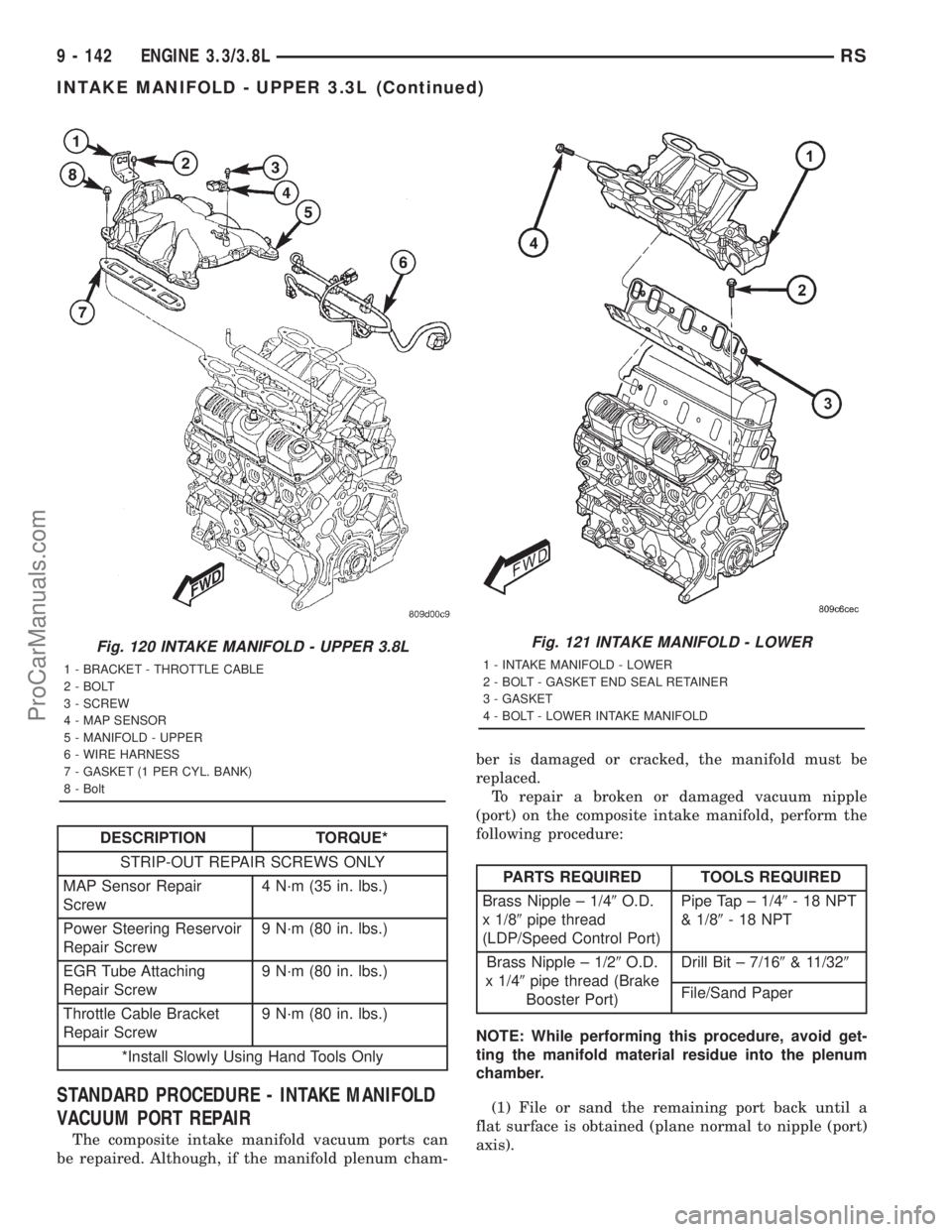
Fig. 120 INTAKE MANIFOLD - UPPER 3.8L
1 - BRACKET - THROTTLE CABLE
2 - BOLT
3 - SCREW
4 - MAP SENSOR
5 - MANIFOLD - UPPER
6 - WIRE HARNESS
7 - GASKET (1 PER CYL. BANK)
8 - Bolt
Fig. 121 INTAKE MANIFOLD - LOWER
1 - INTAKE MANIFOLD - LOWER
2 - BOLT - GASKET END SEAL RETAINER
3 - GASKET
4 - BOLT - LOWER INTAKE MANIFOLD
9 - 142 ENGINE 3.3/3.8LRS
INTAKE MANIFOLD - UPPER 3.3L (Continued)
ProCarManuals.com
Page 1300 of 2321
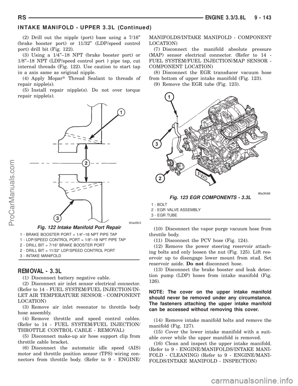
(2) Drill out the nipple (port) base using a 7/16º
(brake booster port) or 11/32º (LDP/speed control
port) drill bit (Fig. 122).
(3) Using a 1/4º±18 NPT (brake booster port) or
1/8º±18 NPT (LDP/speed control port ) pipe tap, cut
internal threads (Fig. 122). Use caution to start tap
in a axis same as original nipple.
(4) Apply MopartThread Sealant to threads of
repair nipple(s).
(5) Install repair nipple(s). Do not over torque
repair nipple(s).
REMOVAL - 3.3L
(1) Disconnect battery negative cable.
(2) Disconnect air inlet sensor electrical connector.
(Refer to 14 - FUEL SYSTEM/FUEL INJECTION/IN-
LET AIR TEMPERATURE SENSOR - COMPONENT
LOCATION)
(3) Remove air inlet resonator to throttle body
hose assembly.
(4) Remove throttle and speed control cables.
(Refer to 14 - FUEL SYSTEM/FUEL INJECTION/
THROTTLE CONTROL CABLE - REMOVAL)
(5) Disconnect make-up air hose support clip from
throttle cable bracket.
(6) Disconnect the automatic idle speed (AIS)
motor and throttle position sensor (TPS) wiring con-
nectors from throttle body. (Refer to 9 - ENGINE/MANIFOLDS/INTAKE MANIFOLD - COMPONENT
LOCATION)
(7) Disconnect the manifold absolute pressure
(MAP) sensor electrical connector. (Refer to 14 -
FUEL SYSTEM/FUEL INJECTION/MAP SENSOR -
COMPONENT LOCATION)
(8) Disconnect the EGR transducer vacuum hose
from bottom of upper intake manifold (Fig. 123).
(9) Remove the EGR tube (Fig. 123).
(10) Disconnect the vapor purge vacuum hose from
throttle body.
(11) Disconnect the PCV hose (Fig. 124).
(12) Remove the power steering reservoir attach-
ing bolts and only loosen the nut (Fig. 125). Lift res-
ervoir up to disengage lower mount from stud. Set
reservoir aside.Do notdisconnect hose.
(13) Disconnect the brake booster and leak detec-
tion pump (LDP) hoses from intake manifold (Fig.
126).
NOTE: The cover on the upper intake manifold
should never be removed under any circumstance.
The fasteners attaching the upper intake manifold
can be accessed without removing this cover.
(14) Remove intake manifold bolts and remove the
manifold (Fig. 127).
(15) Cover the lower intake manifold with a suit-
able cover while the upper manifold is removed.
(16) Clean and inspect the upper intake manifold.
(Refer to 9 - ENGINE/MANIFOLDS/INTAKE MANI-
FOLD - CLEANING) (Refer to 9 - ENGINE/MANI-
FOLDS/INTAKE MANIFOLD - INSPECTION)
Fig. 122 Intake Manifold Port Repair
1 - BRAKE BOOSTER PORT = 1/49±18 NPT PIPE TAP
1 - LDP/SPEED CONTROL PORT = 1/89±18 NPT PIPE TAP
2 - DRILL BIT = 7/169BRAKE BOOSTER PORT
2 - DRILL BIT = 11/329LDP/SPEED CONTROL PORT
3 - INTAKE MANIFOLD
Fig. 123 EGR COMPONENTS - 3.3L
1 - BOLT
2 - EGR VALVE ASSEMBLY
3 - EGR TUBE
RSENGINE 3.3/3.8L9 - 143
INTAKE MANIFOLD - UPPER 3.3L (Continued)
ProCarManuals.com
Page 1301 of 2321
CLEANING
(1) Discard gasket(s).
(2) Clean all sealing surfaces.
INSPECTION
Check manifold for:
²Damage and cracks.
²Mounting surface distortion by using a straight-
edge and thickness gauge.
INSTALLATION - 3.3L
(1) If the following components were removed from
manifold, install and tighten to specifications:
CAUTION: The special screws used for the compos-
ite manifold attached components must be installed
slowly using hand tools only. This requirement is to
prevent the melting of material that causes stripped
threads. If threads become stripped, an oversize
repair screw is available. For more information and
procedure (Refer to 9 - ENGINE/MANIFOLDS/IN-
TAKE MANIFOLD - STANDARD PROCEDURE).
²MAP sensor - 1.7 N´m (15 in. lbs.)
²Throttle cable bracket - 5.6 N´m (50 in. lbs.)
(2) Remove covering on lower intake manifold and
clean surfaces.
(3) Inspect manifold gasket condition. Gaskets can
be re-used, if not damaged. To replace, remove gasket
from upper manifold (Fig. 127). Position new gasket
in seal channel and press lightly in-place. Repeat
procedure for each gasket position.
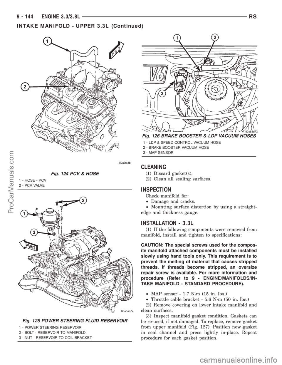
Fig. 124 PCV & HOSE
1 - HOSE - PCV
2 - P C V VA LV E
Fig. 125 POWER STEERING FLUID RESERVOIR
1 - POWER STEERING RESERVOIR
2 - BOLT - RESERVOIR TO MANIFOLD
3 - NUT - RESERVOIR TO COIL BRACKET
Fig. 126 BRAKE BOOSTER & LDP VACUUM HOSES
1 - LDP & SPEED CONTROL VACUUM HOSE
2 - BRAKE BOOSTER VACUUM HOSE
3 - MAP SENSOR
9 - 144 ENGINE 3.3/3.8LRS
INTAKE MANIFOLD - UPPER 3.3L (Continued)
ProCarManuals.com
Page 1302 of 2321
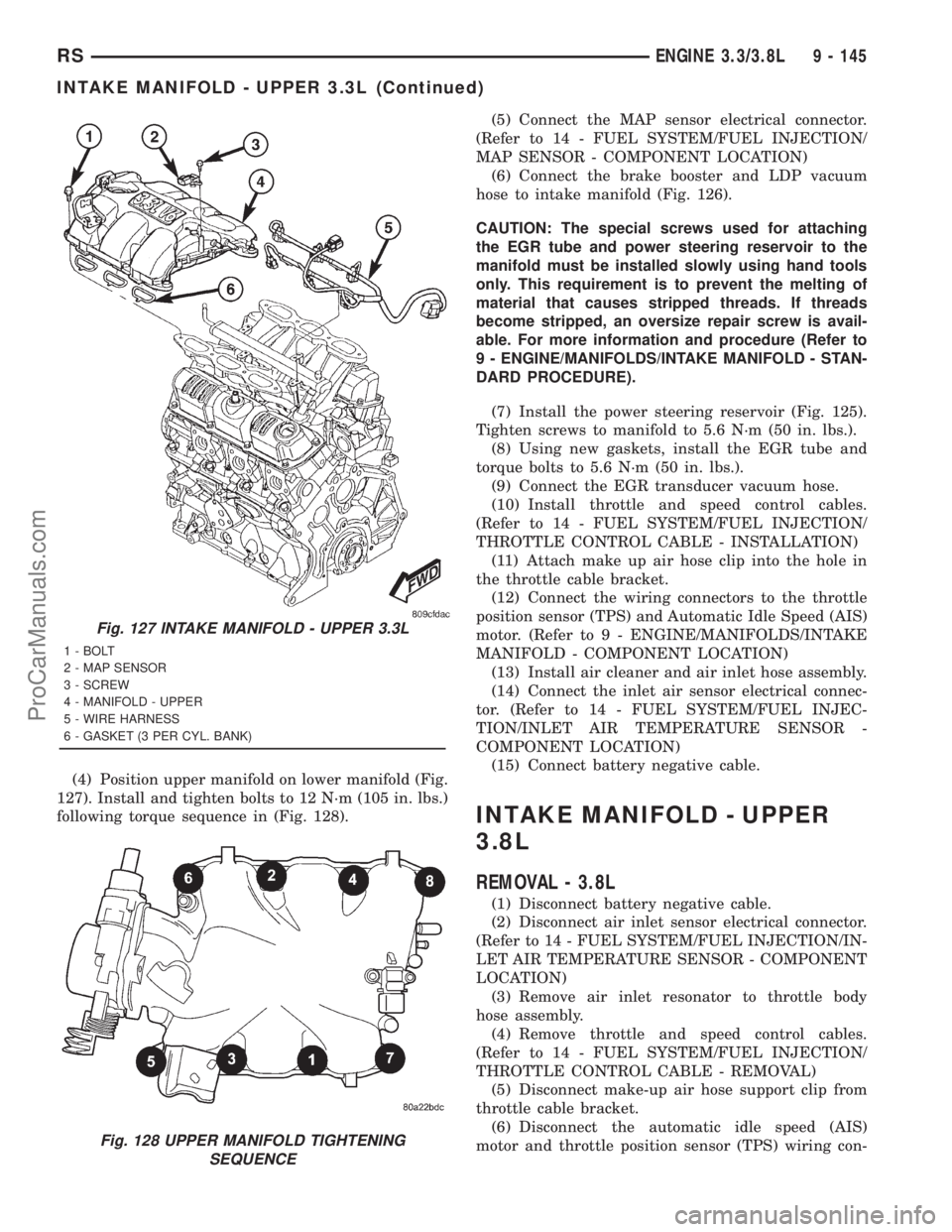
(4) Position upper manifold on lower manifold (Fig.
127). Install and tighten bolts to 12 N´m (105 in. lbs.)
following torque sequence in (Fig. 128).(5) Connect the MAP sensor electrical connector.
(Refer to 14 - FUEL SYSTEM/FUEL INJECTION/
MAP SENSOR - COMPONENT LOCATION)
(6) Connect the brake booster and LDP vacuum
hose to intake manifold (Fig. 126).
CAUTION: The special screws used for attaching
the EGR tube and power steering reservoir to the
manifold must be installed slowly using hand tools
only. This requirement is to prevent the melting of
material that causes stripped threads. If threads
become stripped, an oversize repair screw is avail-
able. For more information and procedure (Refer to
9 - ENGINE/MANIFOLDS/INTAKE MANIFOLD - STAN-
DARD PROCEDURE).
(7) Install the power steering reservoir (Fig. 125).
Tighten screws to manifold to 5.6 N´m (50 in. lbs.).
(8) Using new gaskets, install the EGR tube and
torque bolts to 5.6 N´m (50 in. lbs.).
(9) Connect the EGR transducer vacuum hose.
(10) Install throttle and speed control cables.
(Refer to 14 - FUEL SYSTEM/FUEL INJECTION/
THROTTLE CONTROL CABLE - INSTALLATION)
(11) Attach make up air hose clip into the hole in
the throttle cable bracket.
(12) Connect the wiring connectors to the throttle
position sensor (TPS) and Automatic Idle Speed (AIS)
motor. (Refer to 9 - ENGINE/MANIFOLDS/INTAKE
MANIFOLD - COMPONENT LOCATION)
(13) Install air cleaner and air inlet hose assembly.
(14) Connect the inlet air sensor electrical connec-
tor. (Refer to 14 - FUEL SYSTEM/FUEL INJEC-
TION/INLET AIR TEMPERATURE SENSOR -
COMPONENT LOCATION)
(15) Connect battery negative cable.
INTAKE MANIFOLD - UPPER
3.8L
REMOVAL - 3.8L
(1) Disconnect battery negative cable.
(2) Disconnect air inlet sensor electrical connector.
(Refer to 14 - FUEL SYSTEM/FUEL INJECTION/IN-
LET AIR TEMPERATURE SENSOR - COMPONENT
LOCATION)
(3) Remove air inlet resonator to throttle body
hose assembly.
(4) Remove throttle and speed control cables.
(Refer to 14 - FUEL SYSTEM/FUEL INJECTION/
THROTTLE CONTROL CABLE - REMOVAL)
(5) Disconnect make-up air hose support clip from
throttle cable bracket.
(6) Disconnect the automatic idle speed (AIS)
motor and throttle position sensor (TPS) wiring con-
Fig. 127 INTAKE MANIFOLD - UPPER 3.3L
1 - BOLT
2 - MAP SENSOR
3 - SCREW
4 - MANIFOLD - UPPER
5 - WIRE HARNESS
6 - GASKET (3 PER CYL. BANK)
Fig. 128 UPPER MANIFOLD TIGHTENING
SEQUENCE
RSENGINE 3.3/3.8L9 - 145
INTAKE MANIFOLD - UPPER 3.3L (Continued)
ProCarManuals.com
Page 1303 of 2321
nectors from throttle body. (Refer to 9 - ENGINE/
MANIFOLDS/INTAKE MANIFOLD - COMPONENT
LOCATION)
(7) Disconnect the manifold absolute pressure
(MAP) sensor electrical connector. (Refer to 14 -
FUEL SYSTEM/FUEL INJECTION/MAP SENSOR -
COMPONENT LOCATION)
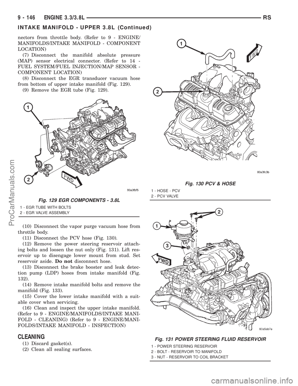
(8) Disconnect the EGR transducer vacuum hose
from bottom of upper intake manifold (Fig. 129).
(9) Remove the EGR tube (Fig. 129).
(10) Disconnect the vapor purge vacuum hose from
throttle body.
(11) Disconnect the PCV hose (Fig. 130).
(12) Remove the power steering reservoir attach-
ing bolts and loosen the nut only (Fig. 131). Lift res-
ervoir up to disengage lower mount from stud. Set
reservoir aside.Do notdisconnect hose.
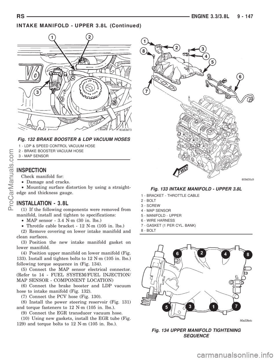
(13) Disconnect the brake booster and leak detec-
tion pump (LDP) hoses from intake manifold (Fig.
132).
(14) Remove intake manifold bolts and remove the
manifold (Fig. 133).
(15) Cover the lower intake manifold with a suit-
able cover when servicing.
(16) Clean and inspect the upper intake manifold.
(Refer to 9 - ENGINE/MANIFOLDS/INTAKE MANI-
FOLD - CLEANING) (Refer to 9 - ENGINE/MANI-
FOLDS/INTAKE MANIFOLD - INSPECTION)
CLEANING
(1) Discard gasket(s).
(2) Clean all sealing surfaces.
Fig. 129 EGR COMPONENTS - 3.8L
1 - EGR TUBE WITH BOLTS
2 - EGR VALVE ASSEMBLY
Fig. 130 PCV & HOSE
1 - HOSE - PCV
2 - P C V VA LV E
Fig. 131 POWER STEERING FLUID RESERVOIR
1 - POWER STEERING RESERVOIR
2 - BOLT - RESERVOIR TO MANIFOLD
3 - NUT - RESERVOIR TO COIL BRACKET
9 - 146 ENGINE 3.3/3.8LRS
INTAKE MANIFOLD - UPPER 3.8L (Continued)
ProCarManuals.com
Page 1304 of 2321
INSPECTION
Check manifold for:
²Damage and cracks.
²Mounting surface distortion by using a straight-
edge and thickness gauge.
INSTALLATION - 3.8L
(1) If the following components were removed from
manifold, install and tighten to specifications:
²MAP sensor - 3.4 N´m (30 in. lbs.)
²Throttle cable bracket - 12 N´m (105 in. lbs.)
(2) Remove covering on lower intake manifold and
clean surfaces.
(3) Position the new intake manifold gasket on
lower manifold.
(4) Position upper manifold on lower manifold (Fig.
133). Install and tighten bolts to 12 N´m (105 in. lbs.)
following torque sequence in (Fig. 134).
(5) Connect the MAP sensor electrical connector.
(Refer to 14 - FUEL SYSTEM/FUEL INJECTION/
MAP SENSOR - COMPONENT LOCATION)
(6) Connect the brake booster and LDP vacuum
hose to intake manifold (Fig. 132).
(7) Connect the PCV hose (Fig. 130).
(8) Install the power steering reservoir (Fig. 131)
and torque fasteners to 12 N´m (105 in. lbs.).
(9) Connect the EGR transducer vacuum hose.
(10) Using new gaskets, install the EGR tube (Fig.
129) and torque bolts to 12 N´m (105 in. lbs.).
Fig. 132 BRAKE BOOSTER & LDP VACUUM HOSES
1 - LDP & SPEED CONTROL VACUUM HOSE
2 - BRAKE BOOSTER VACUUM HOSE
3 - MAP SENSOR
Fig. 133 INTAKE MANIFOLD - UPPER 3.8L
1 - BRACKET - THROTTLE CABLE
2 - BOLT
3 - SCREW
4 - MAP SENSOR
5 - MANIFOLD - UPPER
6 - WIRE HARNESS
7 - GASKET (1 PER CYL. BANK)
8 - BOLT
Fig. 134 UPPER MANIFOLD TIGHTENING
SEQUENCE
RSENGINE 3.3/3.8L9 - 147
INTAKE MANIFOLD - UPPER 3.8L (Continued)
ProCarManuals.com
Page 1308 of 2321
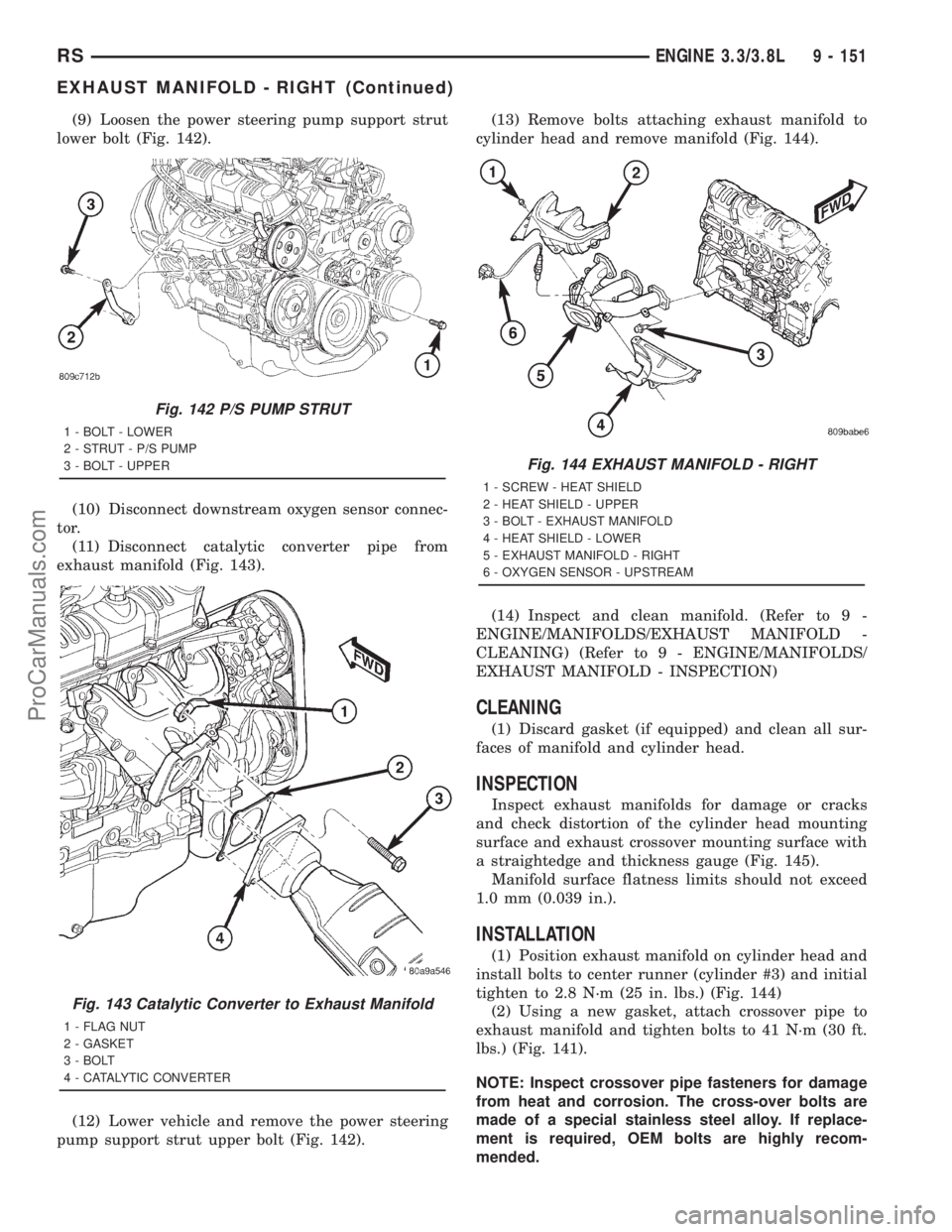
(9) Loosen the power steering pump support strut
lower bolt (Fig. 142).
(10) Disconnect downstream oxygen sensor connec-
tor.
(11) Disconnect catalytic converter pipe from
exhaust manifold (Fig. 143).
(12) Lower vehicle and remove the power steering
pump support strut upper bolt (Fig. 142).(13) Remove bolts attaching exhaust manifold to
cylinder head and remove manifold (Fig. 144).
(14) Inspect and clean manifold. (Refer to 9 -
ENGINE/MANIFOLDS/EXHAUST MANIFOLD -
CLEANING) (Refer to 9 - ENGINE/MANIFOLDS/
EXHAUST MANIFOLD - INSPECTION)
CLEANING
(1) Discard gasket (if equipped) and clean all sur-
faces of manifold and cylinder head.
INSPECTION
Inspect exhaust manifolds for damage or cracks
and check distortion of the cylinder head mounting
surface and exhaust crossover mounting surface with
a straightedge and thickness gauge (Fig. 145).
Manifold surface flatness limits should not exceed
1.0 mm (0.039 in.).
INSTALLATION
(1) Position exhaust manifold on cylinder head and
install bolts to center runner (cylinder #3) and initial
tighten to 2.8 N´m (25 in. lbs.) (Fig. 144)
(2) Using a new gasket, attach crossover pipe to
exhaust manifold and tighten bolts to 41 N´m (30 ft.
lbs.) (Fig. 141).
NOTE: Inspect crossover pipe fasteners for damage
from heat and corrosion. The cross-over bolts are
made of a special stainless steel alloy. If replace-
ment is required, OEM bolts are highly recom-
mended.
Fig. 142 P/S PUMP STRUT
1 - BOLT - LOWER
2 - STRUT - P/S PUMP
3 - BOLT - UPPER
Fig. 143 Catalytic Converter to Exhaust Manifold
1 - FLAG NUT
2 - GASKET
3 - BOLT
4 - CATALYTIC CONVERTER
Fig. 144 EXHAUST MANIFOLD - RIGHT
1 - SCREW - HEAT SHIELD
2 - HEAT SHIELD - UPPER
3 - BOLT - EXHAUST MANIFOLD
4 - HEAT SHIELD - LOWER
5 - EXHAUST MANIFOLD - RIGHT
6 - OXYGEN SENSOR - UPSTREAM
RSENGINE 3.3/3.8L9 - 151
EXHAUST MANIFOLD - RIGHT (Continued)
ProCarManuals.com
Page 1309 of 2321
(3) Install the remaining manifold attaching bolts.
Tighten all bolts to 23 N´m (200 in. lbs.).
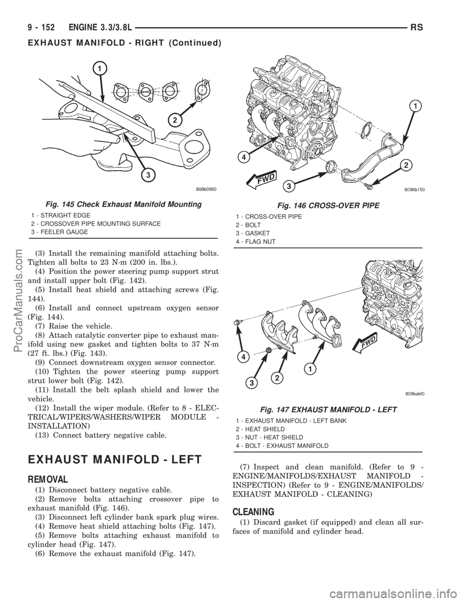
(4) Position the power steering pump support strut
and install upper bolt (Fig. 142).
(5) Install heat shield and attaching screws (Fig.
144).
(6) Install and connect upstream oxygen sensor
(Fig. 144).
(7) Raise the vehicle.
(8) Attach catalytic converter pipe to exhaust man-
ifold using new gasket and tighten bolts to 37 N´m
(27 ft. lbs.) (Fig. 143).
(9) Connect downstream oxygen sensor connector.
(10) Tighten the power steering pump support
strut lower bolt (Fig. 142).
(11) Install the belt splash shield and lower the
vehicle.
(12) Install the wiper module. (Refer to 8 - ELEC-
TRICAL/WIPERS/WASHERS/WIPER MODULE -
INSTALLATION)
(13) Connect battery negative cable.
EXHAUST MANIFOLD - LEFT
REMOVAL
(1) Disconnect battery negative cable.
(2) Remove bolts attaching crossover pipe to
exhaust manifold (Fig. 146).
(3) Disconnect left cylinder bank spark plug wires.
(4) Remove heat shield attaching bolts (Fig. 147).
(5) Remove bolts attaching exhaust manifold to
cylinder head (Fig. 147).
(6) Remove the exhaust manifold (Fig. 147).(7) Inspect and clean manifold. (Refer to 9 -
ENGINE/MANIFOLDS/EXHAUST MANIFOLD -
INSPECTION) (Refer to 9 - ENGINE/MANIFOLDS/
EXHAUST MANIFOLD - CLEANING)
CLEANING
(1) Discard gasket (if equipped) and clean all sur-
faces of manifold and cylinder head.
Fig. 145 Check Exhaust Manifold Mounting
1 - STRAIGHT EDGE
2 - CROSSOVER PIPE MOUNTING SURFACE
3 - FEELER GAUGE
Fig. 146 CROSS-OVER PIPE
1 - CROSS-OVER PIPE
2 - BOLT
3 - GASKET
4 - FLAG NUT
Fig. 147 EXHAUST MANIFOLD - LEFT
1 - EXHAUST MANIFOLD - LEFT BANK
2 - HEAT SHIELD
3 - NUT - HEAT SHIELD
4 - BOLT - EXHAUST MANIFOLD
9 - 152 ENGINE 3.3/3.8LRS
EXHAUST MANIFOLD - RIGHT (Continued)
ProCarManuals.com