2001 DODGE TOWN AND COUNTRY wheel torque
[x] Cancel search: wheel torquePage 1909 of 2321
CLEANING - ALUMINUM WHEEL CARE
Chrome plated and painted aluminum wheels
should be cleaned regularly using mild soap and
water to maintain their luster and to prevent corro-
sion.
Care must be taken in the selection of tire and
wheel cleaning chemicals and equipment to prevent
damage to the wheels. Any of the ªDO NOT USEº
items listed below WILL damage chrome plated and
painted aluminum wheels.
DO NOT USE:
²any abrasive metal cleaner
²any abrasive cleaning pad or brush
²any cleaner that contains an acid (this will
immediately react with and discolor the chromium
surface)
²chrome polish (unless it is buffed off immedi-
ately after application)
²oven cleaner
²a car wash that uses carbide-tipped wheel clean-
ing brushes
SPECIFICATIONS
WHEEL
SPECIFICATIONS
DESCRIPTION SPECIFICATION
Wheel Mounting (Lug)
Nut Hex Size19 mm
Wheel Mounting Stud
SizeM12 x 1.5 mm
TORQUE SPECIFICATIONS
DESCRIPTION N´mFt.
Lbs.In.
Lbs.
Wheel Mounting (Lug ) Nut 135 100 Ð
WHEEL COVER
DESCRIPTION
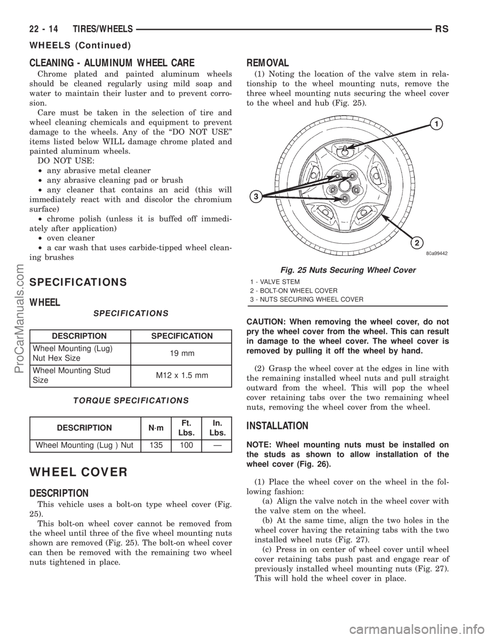
This vehicle uses a bolt-on type wheel cover (Fig.
25).
This bolt-on wheel cover cannot be removed from
the wheel until three of the five wheel mounting nuts
shown are removed (Fig. 25). The bolt-on wheel cover
can then be removed with the remaining two wheel
nuts tightened in place.
REMOVAL
(1) Noting the location of the valve stem in rela-
tionship to the wheel mounting nuts, remove the
three wheel mounting nuts securing the wheel cover
to the wheel and hub (Fig. 25).
CAUTION: When removing the wheel cover, do not
pry the wheel cover from the wheel. This can result
in damage to the wheel cover. The wheel cover is
removed by pulling it off the wheel by hand.
(2) Grasp the wheel cover at the edges in line with
the remaining installed wheel nuts and pull straight
outward from the wheel. This will pop the wheel
cover retaining tabs over the two remaining wheel
nuts, removing the wheel cover from the wheel.
INSTALLATION
NOTE: Wheel mounting nuts must be installed on
the studs as shown to allow installation of the
wheel cover (Fig. 26).
(1) Place the wheel cover on the wheel in the fol-
lowing fashion:
(a) Align the valve notch in the wheel cover with
the valve stem on the wheel.
(b) At the same time, align the two holes in the
wheel cover having the retaining tabs with the two
installed wheel nuts (Fig. 27).
(c) Press in on center of wheel cover until wheel
cover retaining tabs push past and engage rear of
previously installed wheel mounting nuts (Fig. 27).
This will hold the wheel cover in place.
Fig. 25 Nuts Securing Wheel Cover
1 - VALVE STEM
2 - BOLT-ON WHEEL COVER
3 - NUTS SECURING WHEEL COVER
22 - 14 TIRES/WHEELSRS
WHEELS (Continued)
ProCarManuals.com
Page 1910 of 2321
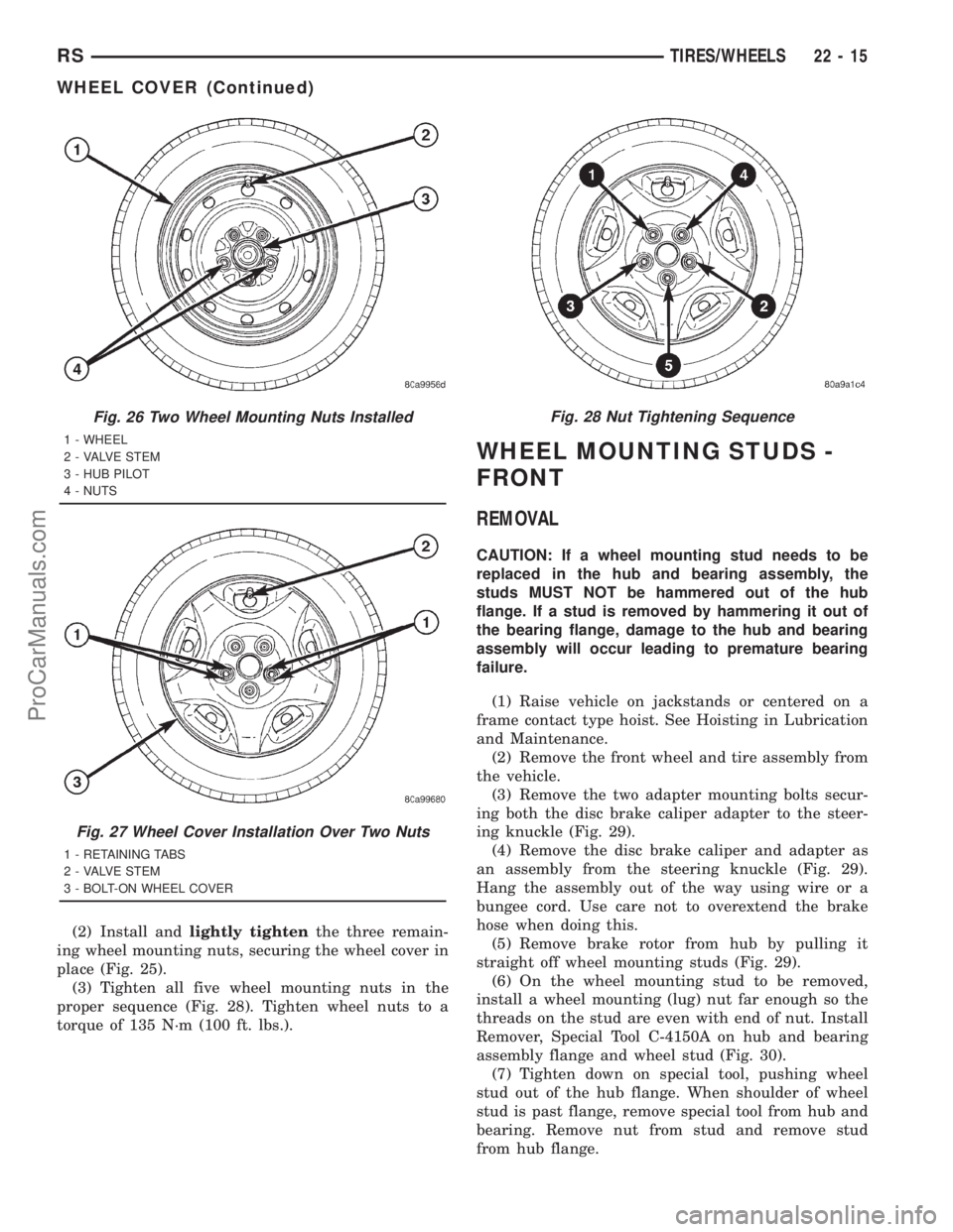
(2) Install andlightly tightenthe three remain-
ing wheel mounting nuts, securing the wheel cover in
place (Fig. 25).
(3) Tighten all five wheel mounting nuts in the
proper sequence (Fig. 28). Tighten wheel nuts to a
torque of 135 N´m (100 ft. lbs.).
WHEEL MOUNTING STUDS -
FRONT
REMOVAL
CAUTION: If a wheel mounting stud needs to be
replaced in the hub and bearing assembly, the
studs MUST NOT be hammered out of the hub
flange. If a stud is removed by hammering it out of
the bearing flange, damage to the hub and bearing
assembly will occur leading to premature bearing
failure.
(1) Raise vehicle on jackstands or centered on a
frame contact type hoist. See Hoisting in Lubrication
and Maintenance.
(2) Remove the front wheel and tire assembly from
the vehicle.
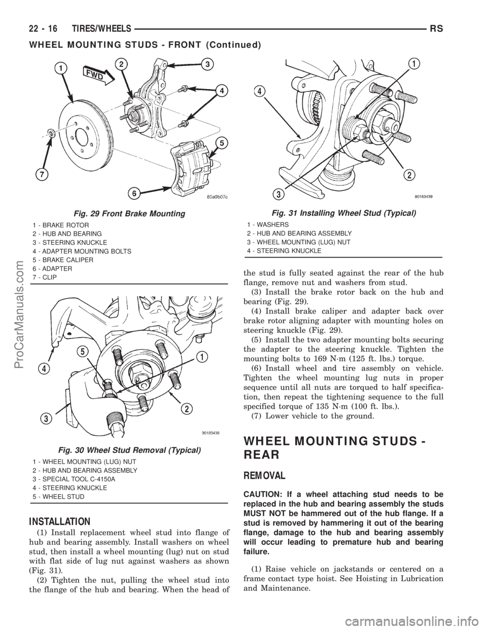
(3) Remove the two adapter mounting bolts secur-
ing both the disc brake caliper adapter to the steer-
ing knuckle (Fig. 29).
(4) Remove the disc brake caliper and adapter as
an assembly from the steering knuckle (Fig. 29).
Hang the assembly out of the way using wire or a
bungee cord. Use care not to overextend the brake
hose when doing this.
(5) Remove brake rotor from hub by pulling it
straight off wheel mounting studs (Fig. 29).
(6) On the wheel mounting stud to be removed,
install a wheel mounting (lug) nut far enough so the
threads on the stud are even with end of nut. Install
Remover, Special Tool C-4150A on hub and bearing
assembly flange and wheel stud (Fig. 30).
(7) Tighten down on special tool, pushing wheel
stud out of the hub flange. When shoulder of wheel
stud is past flange, remove special tool from hub and
bearing. Remove nut from stud and remove stud
from hub flange.
Fig. 26 Two Wheel Mounting Nuts Installed
1 - WHEEL
2 - VALVE STEM
3 - HUB PILOT
4 - NUTS
Fig. 27 Wheel Cover Installation Over Two Nuts
1 - RETAINING TABS
2 - VALVE STEM
3 - BOLT-ON WHEEL COVER
Fig. 28 Nut Tightening Sequence
RSTIRES/WHEELS22-15
WHEEL COVER (Continued)
ProCarManuals.com
Page 1911 of 2321
INSTALLATION
(1) Install replacement wheel stud into flange of
hub and bearing assembly. Install washers on wheel
stud, then install a wheel mounting (lug) nut on stud
with flat side of lug nut against washers as shown
(Fig. 31).
(2) Tighten the nut, pulling the wheel stud into
the flange of the hub and bearing. When the head ofthe stud is fully seated against the rear of the hub
flange, remove nut and washers from stud.
(3) Install the brake rotor back on the hub and
bearing (Fig. 29).
(4) Install brake caliper and adapter back over
brake rotor aligning adapter with mounting holes on
steering knuckle (Fig. 29).
(5) Install the two adapter mounting bolts securing
the adapter to the steering knuckle. Tighten the
mounting bolts to 169 N´m (125 ft. lbs.) torque.
(6) Install wheel and tire assembly on vehicle.
Tighten the wheel mounting lug nuts in proper
sequence until all nuts are torqued to half specifica-
tion, then repeat the tightening sequence to the full
specified torque of 135 N´m (100 ft. lbs.).
(7) Lower vehicle to the ground.
WHEEL MOUNTING STUDS -
REAR
REMOVAL
CAUTION: If a wheel attaching stud needs to be
replaced in the hub and bearing assembly the studs
MUST NOT be hammered out of the hub flange. If a
stud is removed by hammering it out of the bearing
flange, damage to the hub and bearing assembly
will occur leading to premature hub and bearing
failure.
(1) Raise vehicle on jackstands or centered on a
frame contact type hoist. See Hoisting in Lubrication
and Maintenance.
Fig. 29 Front Brake Mounting
1 - BRAKE ROTOR
2 - HUB AND BEARING
3 - STEERING KNUCKLE
4 - ADAPTER MOUNTING BOLTS
5 - BRAKE CALIPER
6 - ADAPTER
7 - CLIP
Fig. 30 Wheel Stud Removal (Typical)
1 - WHEEL MOUNTING (LUG) NUT
2 - HUB AND BEARING ASSEMBLY
3 - SPECIAL TOOL C-4150A
4 - STEERING KNUCKLE
5 - WHEEL STUD
Fig. 31 Installing Wheel Stud (Typical)
1 - WASHERS
2 - HUB AND BEARING ASSEMBLY
3 - WHEEL MOUNTING (LUG) NUT
4 - STEERING KNUCKLE
22 - 16 TIRES/WHEELSRS
WHEEL MOUNTING STUDS - FRONT (Continued)
ProCarManuals.com
Page 1912 of 2321
(2) Remove the rear wheel and tire assembly.
(3) Remove the brake drum or disc brake caliper
and rotor. Refer to Brakes.
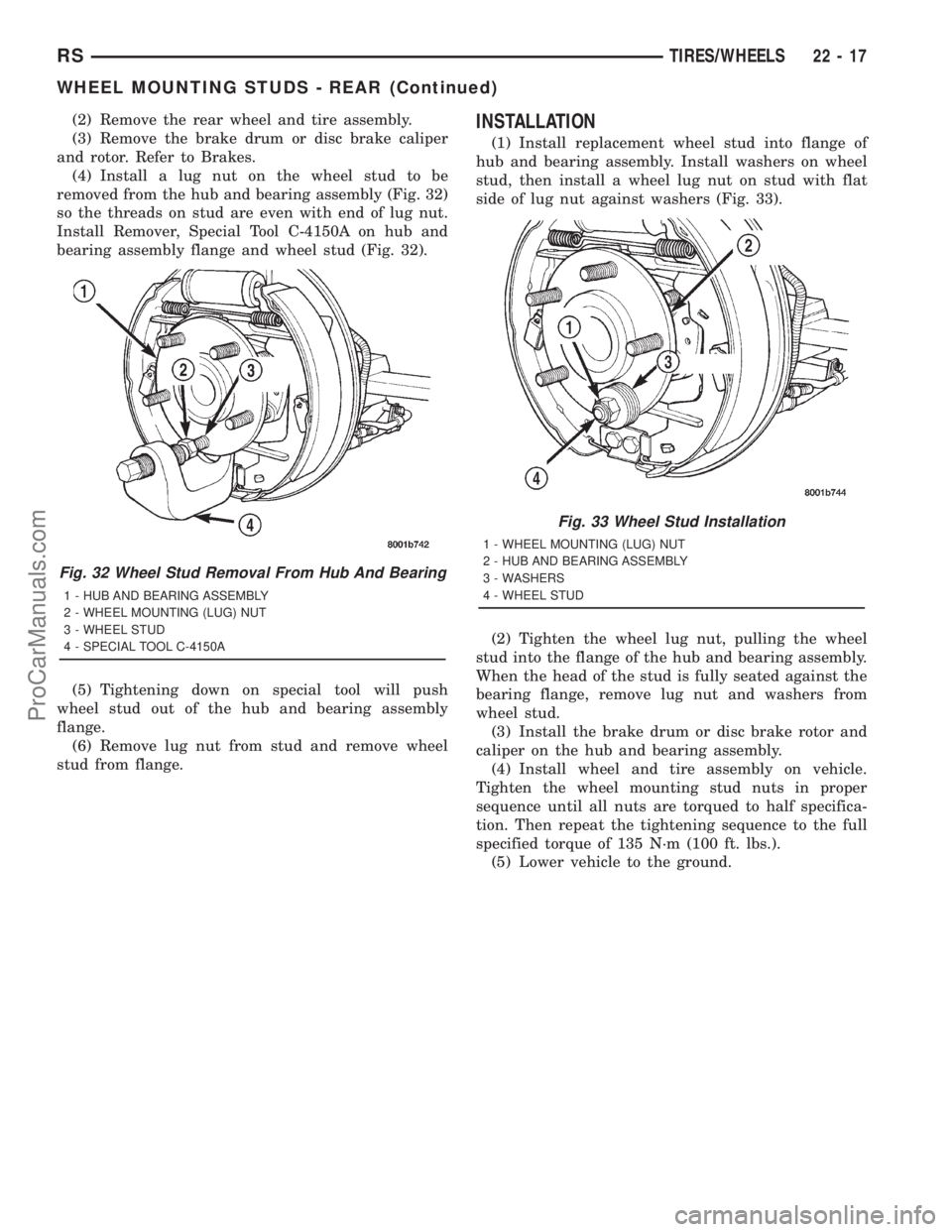
(4) Install a lug nut on the wheel stud to be
removed from the hub and bearing assembly (Fig. 32)
so the threads on stud are even with end of lug nut.
Install Remover, Special Tool C-4150A on hub and
bearing assembly flange and wheel stud (Fig. 32).
(5) Tightening down on special tool will push
wheel stud out of the hub and bearing assembly
flange.
(6) Remove lug nut from stud and remove wheel
stud from flange.INSTALLATION
(1) Install replacement wheel stud into flange of
hub and bearing assembly. Install washers on wheel
stud, then install a wheel lug nut on stud with flat
side of lug nut against washers (Fig. 33).
(2) Tighten the wheel lug nut, pulling the wheel
stud into the flange of the hub and bearing assembly.
When the head of the stud is fully seated against the
bearing flange, remove lug nut and washers from
wheel stud.
(3) Install the brake drum or disc brake rotor and
caliper on the hub and bearing assembly.
(4) Install wheel and tire assembly on vehicle.
Tighten the wheel mounting stud nuts in proper
sequence until all nuts are torqued to half specifica-
tion. Then repeat the tightening sequence to the full
specified torque of 135 N´m (100 ft. lbs.).
(5) Lower vehicle to the ground.
Fig. 32 Wheel Stud Removal From Hub And Bearing
1 - HUB AND BEARING ASSEMBLY
2 - WHEEL MOUNTING (LUG) NUT
3 - WHEEL STUD
4 - SPECIAL TOOL C-4150A
Fig. 33 Wheel Stud Installation
1 - WHEEL MOUNTING (LUG) NUT
2 - HUB AND BEARING ASSEMBLY
3 - WASHERS
4 - WHEEL STUD
RSTIRES/WHEELS22-17
WHEEL MOUNTING STUDS - REAR (Continued)
ProCarManuals.com
Page 2066 of 2321
INSTALLATION
(1) Position check strap on door through speaker
hole.
(2) Install nuts to attach check strap to door end
frame. Tighten nuts to 12 N´m (105 in. lbs.) torque.
(3) Install bolts to attach check strap to A-pillar.
(4) Install door speaker, if equipped.
(5) Install front door trim panel.
DOOR
REMOVAL
(1) Remove front wheelhouse splash shield. (Refer
to 23 - BODY/EXTERIOR/LF WHEELHOUSE
SPLASH SHIELD - REMOVAL)
(2) Disengage clips attaching door harness wire
connector to inner fender brace.
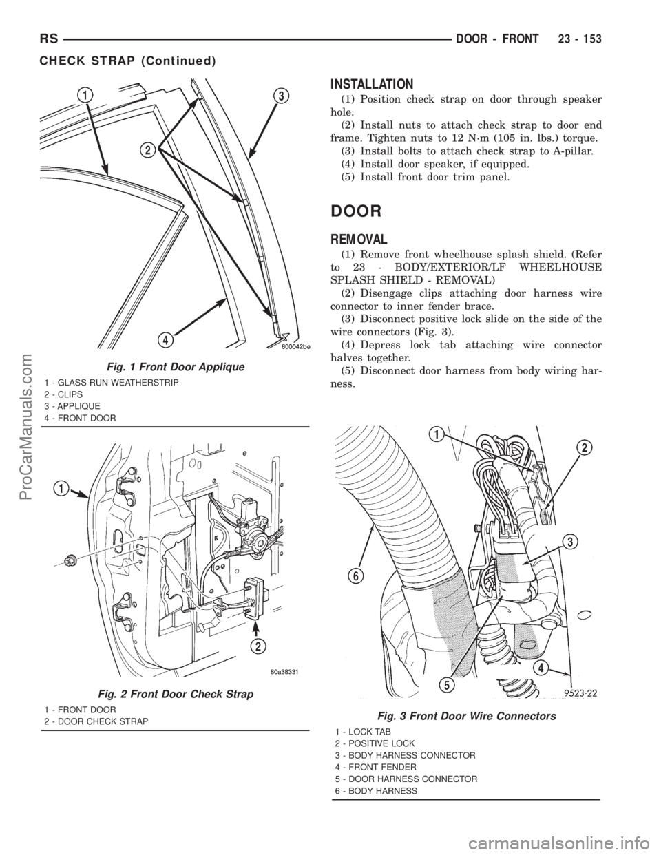
(3) Disconnect positive lock slide on the side of the
wire connectors (Fig. 3).
(4) Depress lock tab attaching wire connector
halves together.
(5) Disconnect door harness from body wiring har-
ness.
Fig. 3 Front Door Wire Connectors
1 - LOCK TAB
2 - POSITIVE LOCK
3 - BODY HARNESS CONNECTOR
4 - FRONT FENDER
5 - DOOR HARNESS CONNECTOR
6 - BODY HARNESS
Fig. 1 Front Door Applique
1 - GLASS RUN WEATHERSTRIP
2 - CLIPS
3 - APPLIQUE
4 - FRONT DOOR
Fig. 2 Front Door Check Strap
1 - FRONT DOOR
2 - DOOR CHECK STRAP
RSDOOR - FRONT23 - 153
CHECK STRAP (Continued)
ProCarManuals.com
Page 2067 of 2321
(6) Remove bolts attaching door check strap to
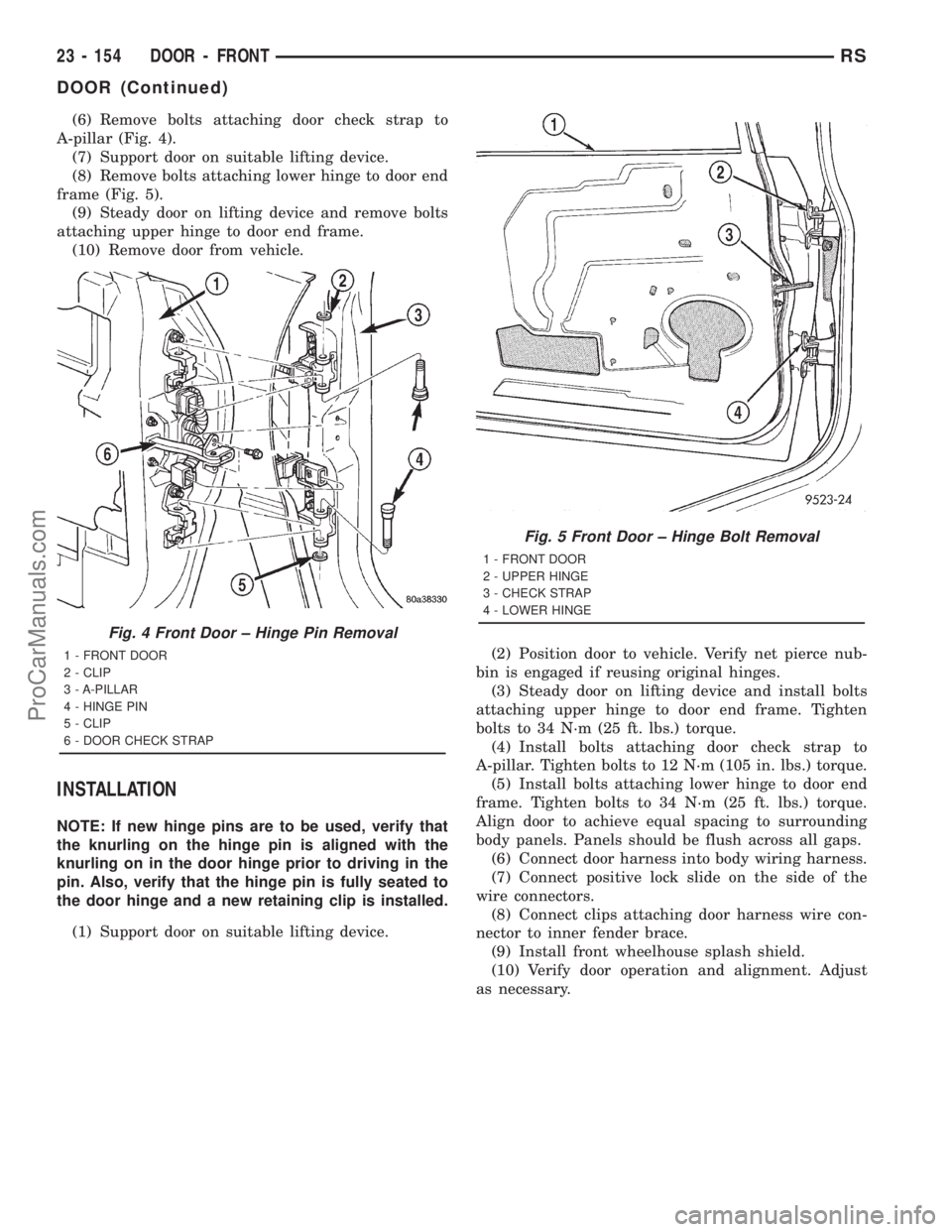
A-pillar (Fig. 4).
(7) Support door on suitable lifting device.
(8) Remove bolts attaching lower hinge to door end
frame (Fig. 5).
(9) Steady door on lifting device and remove bolts
attaching upper hinge to door end frame.
(10) Remove door from vehicle.
INSTALLATION
NOTE: If new hinge pins are to be used, verify that
the knurling on the hinge pin is aligned with the
knurling on in the door hinge prior to driving in the
pin. Also, verify that the hinge pin is fully seated to
the door hinge and a new retaining clip is installed.
(1) Support door on suitable lifting device.(2) Position door to vehicle. Verify net pierce nub-
bin is engaged if reusing original hinges.
(3) Steady door on lifting device and install bolts
attaching upper hinge to door end frame. Tighten
bolts to 34 N´m (25 ft. lbs.) torque.
(4) Install bolts attaching door check strap to
A-pillar. Tighten bolts to 12 N´m (105 in. lbs.) torque.
(5) Install bolts attaching lower hinge to door end
frame. Tighten bolts to 34 N´m (25 ft. lbs.) torque.
Align door to achieve equal spacing to surrounding
body panels. Panels should be flush across all gaps.
(6) Connect door harness into body wiring harness.
(7) Connect positive lock slide on the side of the
wire connectors.
(8) Connect clips attaching door harness wire con-
nector to inner fender brace.
(9) Install front wheelhouse splash shield.
(10) Verify door operation and alignment. Adjust
as necessary.
Fig. 4 Front Door ± Hinge Pin Removal
1 - FRONT DOOR
2 - CLIP
3 - A-PILLAR
4 - HINGE PIN
5 - CLIP
6 - DOOR CHECK STRAP
Fig. 5 Front Door ± Hinge Bolt Removal
1 - FRONT DOOR
2 - UPPER HINGE
3 - CHECK STRAP
4 - LOWER HINGE
23 - 154 DOOR - FRONTRS
DOOR (Continued)
ProCarManuals.com
Page 2107 of 2321
(5) Install fuel filler housing to outer quarter
panel.
(6) Verify that all clips on fuel filler housing are
fully engaged to outer quarter panel.
(7) Engage fuel filler lockout link into clip on fuel
fill blocker latch arm.
(8) Install water shield patch covering access hole
in C-pillar.
(9) Install left quarter trim panel.
GRILLE OPENING
REINFORCEMENT
REMOVAL
(1) Release hood latch and open hood.
(2) Remove bolts attaching hood latch to cross-
member and position latch out of the way.
(3) Remove radiator sight shield.
(4) Remove engine air inlet resonator.
(5) Remove hood cable.
(6) Remove hood prop rod.
(7) Remove screw attaching coolant recovery bottle
to crossmember.
(8) Remove bolts attaching radiator isolators to
crossmember.
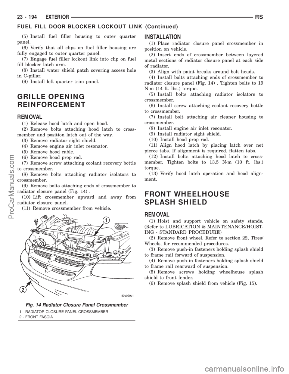
(9) Remove bolts attaching ends of crossmember to
radiator closure panel (Fig. 14) .
(10) Lift crossmember upward and away from
radiator closure panel.
(11) Remove crossmember from vehicle.
INSTALLATION
(1) Place radiator closure panel crossmember in
position on vehicle.
(2) Insert ends of crossmember between layered
metal sections of radiator closure panel at each side
of radiator.
(3) Align with paint breaks around bolt heads.
(4) Install bolts attaching ends of crossmember to
radiator closure panel (Fig. 14) . Tighten bolts to 19
N´m (14 ft. lbs.) torque.
(5) Install bolts attaching radiator isolators to
crossmember.
(6) Install screw attaching coolant recovery bottle
to crossmember.
(7) Install bolt attaching air cleaner housing to
crossmember.
(8) Install engine air inlet resonator.
(9) Install radiator sight shield.
(10) Install hood prop rod.
(11) Align hood latch by placing latch over net
pierce tabs. If alignment is required, flatten tabs.
(12) Install bolts attaching hood latch to cross-
member. Tighten bolts to 13.5 N´m (10 ft. lbs.)
torque.
(13) Verify hood latch operation and hood align-
ment.
FRONT WHEELHOUSE
SPLASH SHIELD
REMOVAL
(1) Hoist and support vehicle on safety stands.
(Refer to LUBRICATION & MAINTENANCE/HOIST-
ING - STANDARD PROCEDURE)
(2) Remove front wheel. Refer to section 22, Tires/
Wheels, for recommended procedures.
(3) Remove push-in fasteners holding splash shield
to frame rail forward of suspension.
(4) Remove push-in fasteners holding splash shield
to frame rail rearward of suspension.
(5) Remove screws holding wheelhouse splash
shield to front fender.
(6) Remove splash shield from vehicle (Fig. 15).
Fig. 14 Radiator Closure Panel Crossmember
1 - RADIATOR CLOSURE PANEL CROSSMEMBER
2 - FRONT FASCIA
23 - 194 EXTERIORRS
FUEL FILL DOOR BLOCKER LOCKOUT LINK (Continued)
ProCarManuals.com
Page 2109 of 2321
INSTALLATION
NOTE: The crossbar assemblies are designed to be
installed in only one way. Check top and bottom
surfaces of the crossbar for the word FRONT and
directional arrows. The directional arrows must
point toward the front of the vehicle.
(1) Place crossbar in position on vehicle.
(2) Work from side to side sliding the crossbar
assembly back a little at a time to ensure it remains
perpendicular to the side rails.
(3) Position first crossbar assembly crossbar at the
second most rearward locator holes. Press the top of
the stanchion lever to lock it into position.
(4) Position the second crossbar assembly in the
second hole from the front. Lock into place.
(5) Place luggage rack riser into position.
(6) Install two fasteners into riser. Tighten fasten-
ers to 4 mm (35 in. lbs.) torque.
REAR QUARTER PANEL/
FENDER AIR EXHAUSTER
DESCRIPTION
Air exhausters, designed to conform to the body
structure, allow air entering at the front of the vehi-
cle to flow out the back. By reducing air pressure
within the vehicle, the exhausters also reduce blower
noise at any given air flow level compared to operat-
ing without them and help reduce door closing effort.
They are located in the lower rear comers of the
body.
REMOVAL
SHORT WHEELBASE
(1) Remove the rear fascia from the body. (Refer to
13 - FRAMES & BUMPERS/BUMPERS/REAR FAS-
CIA - REMOVAL).
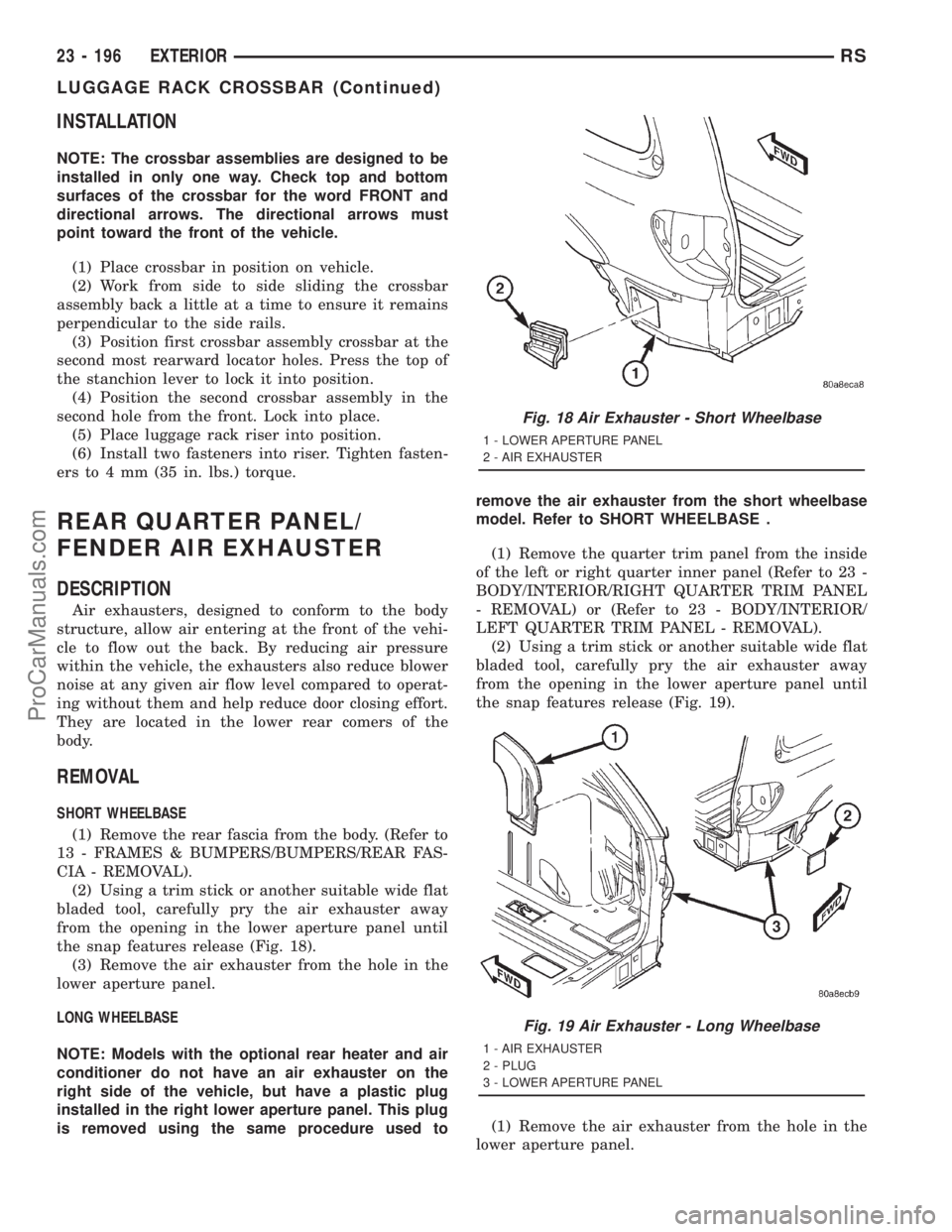
(2) Using a trim stick or another suitable wide flat
bladed tool, carefully pry the air exhauster away
from the opening in the lower aperture panel until
the snap features release (Fig. 18).
(3) Remove the air exhauster from the hole in the
lower aperture panel.
LONG WHEELBASE
NOTE: Models with the optional rear heater and air
conditioner do not have an air exhauster on the
right side of the vehicle, but have a plastic plug
installed in the right lower aperture panel. This plug
is removed using the same procedure used toremove the air exhauster from the short wheelbase
model. Refer to SHORT WHEELBASE .
(1) Remove the quarter trim panel from the inside
of the left or right quarter inner panel (Refer to 23 -
BODY/INTERIOR/RIGHT QUARTER TRIM PANEL
- REMOVAL) or (Refer to 23 - BODY/INTERIOR/
LEFT QUARTER TRIM PANEL - REMOVAL).
(2) Using a trim stick or another suitable wide flat
bladed tool, carefully pry the air exhauster away
from the opening in the lower aperture panel until
the snap features release (Fig. 19).
(1) Remove the air exhauster from the hole in the
lower aperture panel.
Fig. 18 Air Exhauster - Short Wheelbase
1 - LOWER APERTURE PANEL
2 - AIR EXHAUSTER
Fig. 19 Air Exhauster - Long Wheelbase
1 - AIR EXHAUSTER
2 - PLUG
3 - LOWER APERTURE PANEL
23 - 196 EXTERIORRS
LUGGAGE RACK CROSSBAR (Continued)
ProCarManuals.com