2001 DODGE TOWN AND COUNTRY steering
[x] Cancel search: steeringPage 447 of 2321
(2) Using a voltmeter, test for battery voltage at
both sides of horn fuse 7. If voltage is OK, on both
sides of fuse, proceed to Fuse OK. If voltage is OK,
on one side of fuse, the fuse is blown, proceed to Step
3.
(3) Using a suitable ammeter in place of the fuse,
test amperage draw of the horn circuit. If amperage
draw is greater than 20 amps without the horn
switch depressed, a grounded circuit exists between
the fuse and the horn relay. Proceed to Step 4. If
amperage draw is greater than 20 amps with the
horn switch depressed, a grounded circuit exists
between the horn relay and the horn. Proceed to step
Step 5.
(4) Remove the horn relay from the intelligent
power module. If the amperage draw drops to 0
amps, the horn switch or circuit is shorted. Refer to
the appropriate wiring information. The wiring infor-
mation includes wiring diagrams, proper wire and
connector repair procedures, details of wire harness
routing and retention, connector pin-out information
and location views for the various wire harness con-
nectors, splices and grounds. If the amperage draw
does not drop to 0 amps, repair short at the intelli-
gent power module.
(5) Disengage a wire connector from one of the
horns. If amperage drops and the connected horn
sounds, replace the faulty horn. If amperage does not
drop with both horns disconnected and the horn
switch depressed, proceed to Step 6.
(6) Using a continuity tester, with the horns dis-
connected test continuity of the X2 cavity of the horn
relay to ground. Refer to the appropriate wiring
information. The wiring information includes wiring
diagrams, proper wire and connector repair proce-
dures, details of wire harness routing and retention,
connector pin-out information and location views for
the various wire harness connectors, splices and
grounds. If continuity is detected, the circuit is
grounded between the Junction Block and the horns.
Locate and repair pinched harness.
FUSE OK
(1) Remove the horn relay from the intelligent
power module.
(2) Using a continuity tester, Depress horn switch
and test continuity from the X3 cavity of the horn
relay to ground. Refer to the appropriate wiring
information. The wiring information includes wiring
diagrams, proper wire and connector repair proce-
dures, details of wire harness routing and retention,
connector pin-out information and location views for
the various wire harness connectors, splices and
grounds.
(a) If continuity is detected, proceed to Step 3.
(b) If NO continuity, proceed to Step 4.(3) Using a suitable jumper wire, jump across the
fuse F62 cavity and the X2 cavity of the horn relay in
the Junction Block.
(a) If the horn sounds, replace the horn relay.
(b) If the horn does not sound, proceed to Step 4.
(4) Remove airbag trim cover from steering wheel.
Refer to ELECTRICAL, RESTRAINTS.
(5) Test continuity across horn switch connectors
with horn switch depressed.
(a) If continuity is detected, repair open circuit
between the relay and the horn switch.
(b) If NO continuity, replace airbag trim cover.
(6) Install horn relay into intelligent power mod-
ule.
(7) Disengage wire connectors from horns.
(8) Using a voltmeter, with the horn switch
depressed test voltage across horn connector termi-
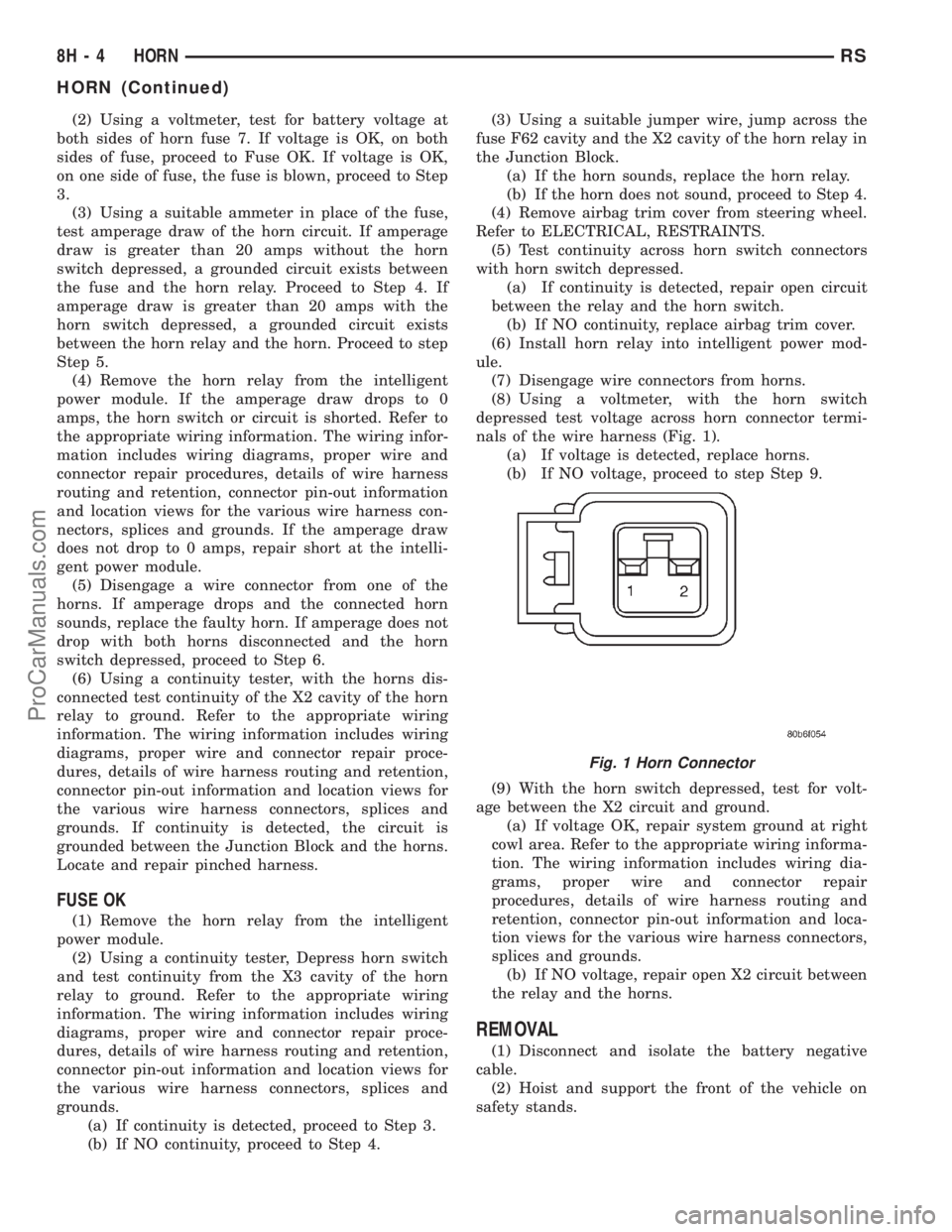
nals of the wire harness (Fig. 1).
(a) If voltage is detected, replace horns.
(b) If NO voltage, proceed to step Step 9.
(9) With the horn switch depressed, test for volt-
age between the X2 circuit and ground.
(a) If voltage OK, repair system ground at right
cowl area. Refer to the appropriate wiring informa-
tion. The wiring information includes wiring dia-
grams, proper wire and connector repair
procedures, details of wire harness routing and
retention, connector pin-out information and loca-
tion views for the various wire harness connectors,
splices and grounds.
(b) If NO voltage, repair open X2 circuit between
the relay and the horns.
REMOVAL
(1) Disconnect and isolate the battery negative
cable.
(2) Hoist and support the front of the vehicle on
safety stands.
Fig. 1 Horn Connector
8H - 4 HORNRS
HORN (Continued)
ProCarManuals.com
Page 455 of 2321

IGNITION COIL
DESCRIPTION
The ignition coil assembly consists of 2 or 3 inde-
pendent coils molded together (Fig. 10) or (Fig. 11).
The coil assembly for the 3.3/3.8L is mounted on the
intake manifold. The coil assembly for the 2.4L is
mounted on the cylinder head cover. Spark plug
cables route to each cylinder from the coil.
OPERATION
The coil fires two spark plugs every power stroke.
One plug is the cylinder under compression, the
other cylinder fires on the exhaust stroke. The Pow-
ertrain Control Module (PCM) determines which of
the coils to charge and fire at the correct time.
The Auto Shutdown (ASD) relay provides battery
voltage to the ignition coil. The PCM provides a
ground contact (circuit) for energizing the coil. When
the PCM breaks the contact, the magnetic energy in
the coil transfers to the secondary causing the spark.
The PCM will de-energize the ASD relay if it does
not receive the crankshaft position sensor and cam-
shaft position sensor inputs. Refer to Auto Shutdown
(ASD) RelayÐPCM Output, in this section for relay
operation.
REMOVAL - 2.4L
The electronic ignition coil pack attaches directly
to the valve cover.
(1) Diconnect the negative battery cable.
(2) Disconnect electrical connector from coil pack
(3) Remove coil pack mounting bolts.(4) Remove coil pack and heat shield (Fig. 10).
REMOVAL - 3.3/3.8L
(1) Disconnect the negative battery cable.
(2) Remove the throttle and speed control cables
from clip.
(3) Remove 2 bolts from the Power steering reser-
voir to intake manifold.
(4) Loosen the lower nut for the power steering
reservoir from stud on ignition coil bracket.
(5) Reposition the Power steering reservoir (Fig.
12).
(6) Remove the ignition cables from the ignition
coil.
(7) Disconnect the electrical connector from the
ignition coil.
(8) Remove 2 nuts from the ignition coil studs.
(9) Remove 2 bolts from ignition coil, remove coil.
INSTALLATION - 2.4L
(1) Install ignition coil and heat shield to valve
cover and tighten bolts.
(2) Connect the electrical connector to the ignition
coil.
(3) Transfer spark plug cables to new coil pack.
The coil pack towers are numbered with the cylinder
identification. Be sure the ignition cables are fully
seated onto the towers.
(4) Connect the negative battery cable.
Fig. 10 IGNITION COIL - 2.4L
Fig. 11 IGNITION COIL - 3.3/3.8L
1 - IGNITION COIL
8I - 6 IGNITION CONTROLRS
ProCarManuals.com
Page 456 of 2321

INSTALLATION - 3.3/3.8L
(1) Install coil over studs on bracket.
(2) Install 2 bolts to ignition coil.
(3) Install 2 nuts to the ignition coil studs. Tighten
nuts and bolts.
(4) Connect the electrical connector to the ignition
coil.
(5) Install the ignition cables to the ignition coil.
(6) Reposition the Power steering reservoir. Slide
bracket over the mounting stud (Fig. 12).
(7) Install 2 bolts the Power steering reservoir to
intake manifold.
(8) Tighten the lower nut to stud on ignition coil
bracket.
(9) Install the throttle and speed control cables to
clip.
(10) Connect the negative battery cable.
KNOCK SENSOR
DESCRIPTION
The knock sensor threads into the cylinder block.
The knock sensor is designed to detect engine vibra-
tion that is caused by detonation.
OPERATION
When the knock sensor detects a knock in one of
the cylinders, it sends an input signal to the PCM. In
response, the PCM retards ignition timing for all cyl-
inders by a scheduled amount.Knock sensors contain a piezoelectric material
which constantly vibrates and sends an input voltage
(signal) to the PCM while the engine operates. As the
intensity of the crystal's vibration increases, the
knock sensor output voltage also increases.
The voltage signal produced by the knock sensor
increases with the amplitude of vibration. The PCM
receives as an input the knock sensor voltage signal.
If the signal rises above a predetermined level, the
PCM will store that value in memory and retard
ignition timing to reduce engine knock. If the knock
sensor voltage exceeds a preset value, the PCM
retards ignition timing for all cylinders. It is not a
selective cylinder retard.
The PCM ignores knock sensor input during engine
idle conditions. Once the engine speed exceeds a
specified value, knock retard is allowed.
Knock retard uses its own short term and long
term memory program.
Long term memory stores previous detonation
information in its battery-backed RAM. The maxi-
mum authority that long term memory has over tim-
ing retard can be calibrated.
Short term memory is allowed to retard timing up
to a preset amount under all operating conditions (as
long as rpm is above the minimum rpm) except WOT.
The PCM, using short term memory, can respond
quickly to retard timing when engine knock is
detected. Short term memory is lost any time the
ignition key is turned off.
NOTE: Over or under tightening affects knock sen-
sor performance, possibly causing improper spark
control.
REMOVAL - 2.4L
The knock sensor threads into the side of the cyl-
inder block in front of the starter (Fig. 13).
(1) Disconnect electrical connector from knock sen-
sor.
(2) Use a crow foot socket to remove the knock
sensors.
REMOVAL - 3.8L
The knock sensor threads into the side of the cyl-
inder block in the rear.
(1) Disconnect the negative battery cable.
(2) Raise vehicle and support.
(3) On All Wheel Drive vehicles remove the PTU
(Power Transfer Unit), refer to the Transmission sec-
tion for more information.
(4) Disconnect electrical connector from knock sen-
sor.
(5) Use a crow foot socket to remove the knock
sensor.
Fig. 12 IGNITION COIL BRACKET 3.3/3.8L
RSIGNITION CONTROL8I-7
IGNITION COIL (Continued)
ProCarManuals.com
Page 469 of 2321
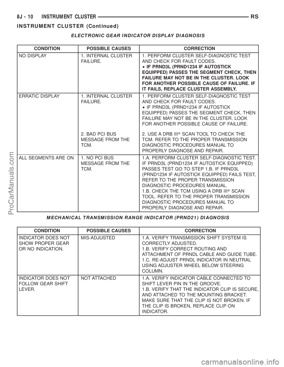
ELECTRONIC GEAR INDICATOR DISPLAY DIAGNOSIS
CONDITION POSSIBLE CAUSES CORRECTION
NO DISPLAY 1. INTERNAL CLUSTER
FAILURE.1. PERFORM CLUSTER SELF-DIAGNOSTIC TEST
AND CHECK FOR FAULT CODES.
²IF PRND3L (PRND1234 IF AUTOSTICK
EQUIPPED) PASSES THE SEGMENT CHECK, THEN
FAILURE MAY NOT BE IN THE CLUSTER. LOOK
FOR ANOTHER POSSIBLE CAUSE OF FAILURE. IF
IT FAILS, REPLACE CLUSTER ASSEMBLY.
ERRATIC DISPLAY 1. INTERNAL CLUSTER
FAILURE.1. PERFORM CLUSTER SELF-DIAGNOSTIC TEST
AND CHECK FOR FAULT CODES.
²IF PRND3L (PRND1234 IF AUTOSTICK
EQUIPPED) PASSES THE SEGMENT CHECK, THEN
FAILURE MAY NOT BE IN THE CLUSTER. LOOK
FOR ANOTHER POSSIBLE CAUSE OF FAILURE.
2. BAD PCI BUS
MESSAGE FROM THE
TCM.2. USE A DRB IIITSCAN TOOL TO CHECK THE
TCM. REFER TO THE PROPER TRANSMISSION
DIAGNOSTIC PROCEDURES MANUAL TO
PROPERLY DIAGNOSE AND REPAIR.
ALL SEGMENTS ARE ON 1. NO PCI BUS
MESSAGE FROM THE
TCM.1.A. PERFORM CLUSTER SELF-DIAGNOSTIC TEST.
IF PRND3L (PRND1234 IF AUTOSTICK EQUIPPED)
PASSES TEST GO TO STEP 1.B. IF PRND3L
(PRND1234 IF AUTOSTICK EQUIPPED) FAILS TEST,
REFER TO THE PROPER TRANSMISSION
DIAGNOSTIC PROCEDURES MANUAL.
1.B. CHECK THE TCM USING A DRB IIITSCAN
TOOL. REFER TO THE PROPER TRANSMISSION
DIAGNOSTIC PROCEDURES MANUAL TO
PROPERLY DIAGNOSE AND REPAIR.
MECHANICAL TRANSMISSION RANGE INDICATOR (PRND21) DIAGNOSIS
CONDITION POSSIBLE CAUSES CORRECTION
INDICATOR DOES NOT
SHOW PROPER GEAR
OR NO INDICATION.MIS-ADJUSTED 1.A. VERIFY TRANSMISSION SHIFT SYSTEM IS
CORRECTLY ADJUSTED.
1.B. VERIFY CORRECT ROUTING AND
ATTACHMENT OF PRNDL CABLE AND GUIDE TUBE.
1.C. RE-ADJUST PRNDL INDICATOR IN NEUTRAL
USING ADJUSTER WHEEL BELOW STEERING
COLUMN.
INDICATOR DOES NOT
FOLLOW GEAR SHIFT
LEVER.NOT ATTACHED 1.A. VERIFY INDICATOR CABLE CONNECTED TO
SHIFT LEVER PIN IN THE GROOVE.
1.B. VERIFY THAT THE INDICATOR CLIP IS SECURE,
AND ATTACHED TO THE MOUNTING BRACKET.
MAKE SURE THAT THE CLIP IS NOT BROKEN. IF
THE CLIP IS BROKEN, REPLACE CLIP ON
INDICATOR.
8J - 10 INSTRUMENT CLUSTERRS
INSTRUMENT CLUSTER (Continued)
ProCarManuals.com
Page 470 of 2321
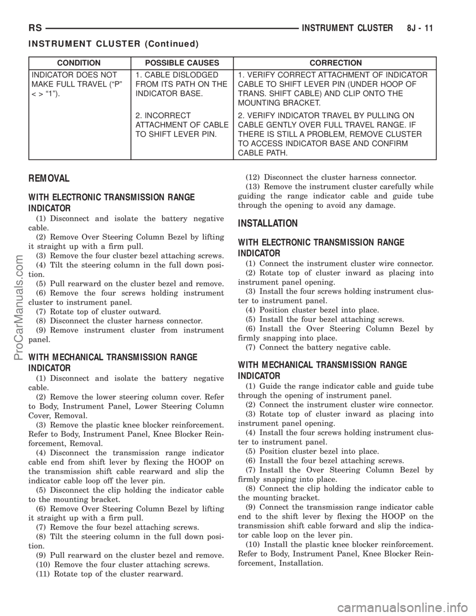
CONDITION POSSIBLE CAUSES CORRECTION
INDICATOR DOES NOT
MAKE FULL TRAVEL (ªPº
< > ª1º).1. CABLE DISLODGED
FROM ITS PATH ON THE
INDICATOR BASE.1. VERIFY CORRECT ATTACHMENT OF INDICATOR
CABLE TO SHIFT LEVER PIN (UNDER HOOP OF
TRANS. SHIFT CABLE) AND CLIP ONTO THE
MOUNTING BRACKET.
2. INCORRECT
ATTACHMENT OF CABLE
TO SHIFT LEVER PIN.2. VERIFY INDICATOR TRAVEL BY PULLING ON
CABLE GENTLY OVER FULL TRAVEL RANGE. IF
THERE IS STILL A PROBLEM, REMOVE CLUSTER
TO ACCESS INDICATOR BASE AND CONFIRM
CABLE PATH.
REMOVAL
WITH ELECTRONIC TRANSMISSION RANGE
INDICATOR
(1) Disconnect and isolate the battery negative
cable.
(2) Remove Over Steering Column Bezel by lifting
it straight up with a firm pull.
(3) Remove the four cluster bezel attaching screws.
(4) Tilt the steering column in the full down posi-
tion.
(5) Pull rearward on the cluster bezel and remove.
(6) Remove the four screws holding instrument
cluster to instrument panel.
(7) Rotate top of cluster outward.
(8) Disconnect the cluster harness connector.
(9) Remove instrument cluster from instrument
panel.
WITH MECHANICAL TRANSMISSION RANGE
INDICATOR
(1) Disconnect and isolate the battery negative
cable.
(2) Remove the lower steering column cover. Refer
to Body, Instrument Panel, Lower Steering Column
Cover, Removal.
(3) Remove the plastic knee blocker reinforcement.
Refer to Body, Instrument Panel, Knee Blocker Rein-
forcement, Removal.
(4) Disconnect the transmission range indicator
cable end from shift lever by flexing the HOOP on
the transmission shift cable rearward and slip the
indicator cable loop off the lever pin.
(5) Disconnect the clip holding the indicator cable
to the mounting bracket.
(6) Remove Over Steering Column Bezel by lifting
it straight up with a firm pull.
(7) Remove the four bezel attaching screws.
(8) Tilt the steering column in the full down posi-
tion.
(9) Pull rearward on the cluster bezel and remove.
(10) Remove the four cluster attaching screws.
(11) Rotate top of the cluster rearward.(12) Disconnect the cluster harness connector.
(13) Remove the instrument cluster carefully while
guiding the range indicator cable and guide tube
through the opening to avoid any damage.
INSTALLATION
WITH ELECTRONIC TRANSMISSION RANGE
INDICATOR
(1) Connect the instrument cluster wire connector.
(2) Rotate top of cluster inward as placing into
instrument panel opening.
(3) Install the four screws holding instrument clus-
ter to instrument panel.
(4) Position cluster bezel into place.
(5) Install the four bezel attaching screws.
(6) Install the Over Steering Column Bezel by
firmly snapping into place.
(7) Connect the battery negative cable.
WITH MECHANICAL TRANSMISSION RANGE
INDICATOR
(1) Guide the range indicator cable and guide tube
through the opening of instrument panel.
(2) Connect the instrument cluster wire connector.
(3) Rotate top of cluster inward as placing into
instrument panel opening.
(4) Install the four screws holding instrument clus-
ter to instrument panel.
(5) Position cluster bezel into place.
(6) Install the four bezel attaching screws.
(7) Install the Over Steering Column Bezel by
firmly snapping into place.
(8) Connect the clip holding the indicator cable to
the mounting bracket.
(9) Connect the transmission range indicator cable
end to the shift lever by flexing the HOOP on the
transmission shift cable forward and slip the indica-
tor cable loop on the lever pin.
(10) Install the plastic knee blocker reinforcement.
Refer to Body, Instrument Panel, Knee Blocker Rein-
forcement, Installation.
RSINSTRUMENT CLUSTER8J-11
INSTRUMENT CLUSTER (Continued)
ProCarManuals.com
Page 471 of 2321
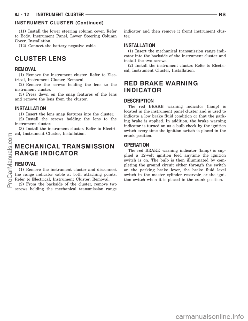
(11) Install the lower steering column cover. Refer
to Body, Instrument Panel, Lower Steering Column
Cover, Installation.
(12) Connect the battery negative cable.
CLUSTER LENS
REMOVAL
(1) Remove the instrument cluster. Refer to Elec-
trical, Instrument Cluster, Removal.
(2) Remove the screws holding the lens to the
instrument cluster.
(3) Press down on the snap features of the lens
and remove the lens from the cluster.
INSTALLATION
(1) Insert the lens snap features into the cluster.
(2) Install the screws holding the lens to the
instrument cluster.
(3) Install the instrument cluster. Refer to Electri-
cal, Instrument Cluster, Installation.
MECHANICAL TRANSMISSION
RANGE INDICATOR
REMOVAL
(1) Remove the instrument cluster and disconnect
the range indicator cable at both attaching points.
Refer to Electrical, Instrument Cluster, Removal.
(2) From the backside of the cluster, remove two
screws holding the mechanical transmission rangeindicator and then remove it fromt instrument clus-
ter.
INSTALLATION
(1) Insert the mechanical transmission range indi-
cator into the backside of the instrument cluster and
install the two screws.
(2) Install the instrument cluster. Refer to Electri-
cal, Instrument Cluster, Installation.
RED BRAKE WARNING
INDICATOR
DESCRIPTION
The red BRAKE warning indicator (lamp) is
located in the instrument panel cluster and is used to
indicate a low brake fluid condition or that the park-
ing brake is applied. In addition, the brake warning
indicator is turned on as a bulb check by the ignition
switch every time the ignition switch is placed in the
crank position.
OPERATION
The red BRAKE warning indicator (lamp) is sup-
plied a 12-volt ignition feed anytime the ignition
switch is on. The bulb is then illuminated by com-
pleting the ground circuit either through the switch
on the parking brake lever, the brake fluid level
switch in the master cylinder reservoir, or the igni-
tion switch when it is placed in the crank position.
8J - 12 INSTRUMENT CLUSTERRS
INSTRUMENT CLUSTER (Continued)
ProCarManuals.com
Page 481 of 2321
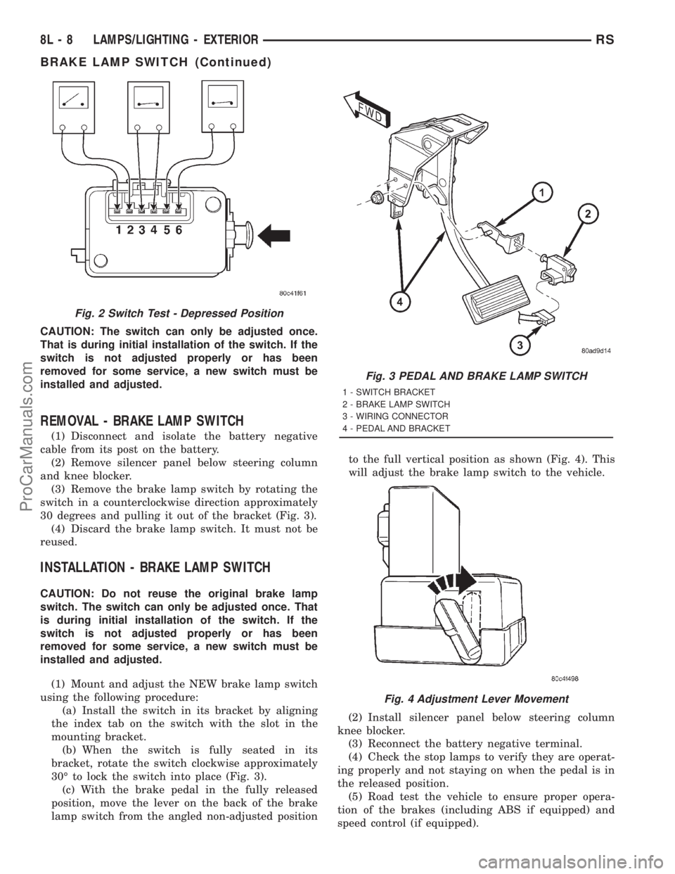
CAUTION: The switch can only be adjusted once.
That is during initial installation of the switch. If the
switch is not adjusted properly or has been
removed for some service, a new switch must be
installed and adjusted.
REMOVAL - BRAKE LAMP SWITCH
(1) Disconnect and isolate the battery negative
cable from its post on the battery.
(2) Remove silencer panel below steering column
and knee blocker.
(3) Remove the brake lamp switch by rotating the
switch in a counterclockwise direction approximately
30 degrees and pulling it out of the bracket (Fig. 3).
(4) Discard the brake lamp switch. It must not be
reused.
INSTALLATION - BRAKE LAMP SWITCH
CAUTION: Do not reuse the original brake lamp
switch. The switch can only be adjusted once. That
is during initial installation of the switch. If the
switch is not adjusted properly or has been
removed for some service, a new switch must be
installed and adjusted.
(1) Mount and adjust the NEW brake lamp switch
using the following procedure:
(a) Install the switch in its bracket by aligning
the index tab on the switch with the slot in the
mounting bracket.
(b) When the switch is fully seated in its
bracket, rotate the switch clockwise approximately
30É to lock the switch into place (Fig. 3).
(c) With the brake pedal in the fully released
position, move the lever on the back of the brake
lamp switch from the angled non-adjusted positionto the full vertical position as shown (Fig. 4). This
will adjust the brake lamp switch to the vehicle.
(2) Install silencer panel below steering column
knee blocker.
(3) Reconnect the battery negative terminal.
(4) Check the stop lamps to verify they are operat-
ing properly and not staying on when the pedal is in
the released position.
(5) Road test the vehicle to ensure proper opera-
tion of the brakes (including ABS if equipped) and
speed control (if equipped).
Fig. 2 Switch Test - Depressed Position
Fig. 3 PEDAL AND BRAKE LAMP SWITCH
1 - SWITCH BRACKET
2 - BRAKE LAMP SWITCH
3 - WIRING CONNECTOR
4 - PEDAL AND BRACKET
Fig. 4 Adjustment Lever Movement
8L - 8 LAMPS/LIGHTING - EXTERIORRS
BRAKE LAMP SWITCH (Continued)
ProCarManuals.com
Page 484 of 2321
HEADLAMP
REMOVAL
(1)Disconnect and isolate the battery negative cable.
(2) Remove headlamp unit retaining screws.
(3) Remove headlamp unit to expose back of unit.
(4) Remove wiring connector from bulb.
(5) Rotate headlamp bulb retaining ring counter-
clockwise.
(6) Pull headlamp bulb and remove from headlamp
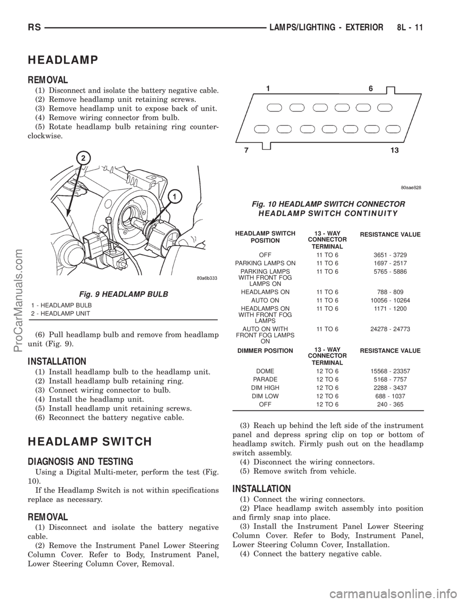
unit (Fig. 9).
INSTALLATION
(1) Install headlamp bulb to the headlamp unit.
(2) Install headlamp bulb retaining ring.
(3) Connect wiring connector to bulb.
(4) Install the headlamp unit.
(5) Install headlamp unit retaining screws.
(6) Reconnect the battery negative cable.
HEADLAMP SWITCH
DIAGNOSIS AND TESTING
Using a Digital Multi-meter, perform the test (Fig.
10).
If the Headlamp Switch is not within specifications
replace as necessary.
REMOVAL
(1) Disconnect and isolate the battery negative
cable.
(2) Remove the Instrument Panel Lower Steering
Column Cover. Refer to Body, Instrument Panel,
Lower Steering Column Cover, Removal.(3) Reach up behind the left side of the instrument
panel and depress spring clip on top or bottom of
headlamp switch. Firmly push out on the headlamp
switch assembly.
(4) Disconnect the wiring connectors.
(5) Remove switch from vehicle.
INSTALLATION
(1) Connect the wiring connectors.
(2) Place headlamp switch assembly into position
and firmly snap into place.
(3) Install the Instrument Panel Lower Steering
Column Cover. Refer to Body, Instrument Panel,
Lower Steering Column Cover, Installation.
(4) Connect the battery negative cable.
Fig. 9 HEADLAMP BULB
1 - HEADLAMP BULB
2 - HEADLAMP UNIT
Fig. 10 HEADLAMP SWITCH CONNECTOR
HEADLAMP SWITCH CONTINUITY
HEADLAMP SWITCH
POSITION13-WAY
CONNECTOR
TERMINALRESISTANCE VALUE
OFF 11 TO 6 3651 - 3729
PARKING LAMPS ON 11 TO 6 1697 - 2517
PARKING LAMPS
WITH FRONT FOG
LAMPS ON11 TO 6 5765 - 5886
HEADLAMPS ON 11 TO 6 788 - 809
AUTO ON 11 TO 6 10056 - 10264
HEADLAMPS ON
WITH FRONT FOG
LAMPS11 TO 6 1171 - 1200
AUTO ON WITH
FRONT FOG LAMPS
ON11 TO 6 24278 - 24773
DIMMER POSITION13-WAY
CONNECTOR
TERMINALRESISTANCE VALUE
DOME 12 TO 6 15568 - 23357
PARADE 12 TO 6 5168 - 7757
DIM HIGH 12 TO 6 2288 - 3437
DIM LOW 12 TO 6 688 - 1037
OFF 12 TO 6 240 - 365
RSLAMPS/LIGHTING - EXTERIOR8L-11
ProCarManuals.com