2001 DODGE TOWN AND COUNTRY battery location
[x] Cancel search: battery locationPage 1254 of 2321
(9) Install the cylinder head covers. (Refer to 9 -
ENGINE/CYLINDER HEAD/CYLINDER HEAD
COVER(S) - INSTALLATION)
(10) Install the exhaust manifolds. (Refer to 9 -
ENGINE/MANIFOLDS/EXHAUST MANIFOLD -
INSTALLATION)
(11) Install new O-ring on dipstick tube. Install
dipstick tube assembly (Fig. 16).
(12) Install the spark plugs.
(13) Install upper and lower intake manifolds.
(Refer to 9 - ENGINE/MANIFOLDS/INTAKE MANI-
FOLD - INSTALLATION)
(14) Fill the cooling system. (Refer to 7 - COOL-
ING - STANDARD PROCEDURE)
(15) Connect negative cable to battery.
CYLINDER HEAD COVER(S)
DESCRIPTION
The cylinder head covers are made of stamped
steel. The covers are sealed with steel reinforced sil-
icon rubber gaskets. The cylinder head cover uses
rubber isolators at each fastener location (Fig. 21).
NOTE: Due to the tight packaging near the cylinder
head covers, which makes spill clean-up difficult, a
spill during an engine oil change may be misinter-
preted as an oil leak. When investigating an oil leak
in the location of the cylinder head covers and
intake manifold, follow the procedure found in Oil
Leak Diagnosis (Refer to 9 - ENGINE - DIAGNOSIS
AND TESTING) for determining the source of a leak.
CYLINDER HEAD COVER -
RIGHT
REMOVAL
(1) Disconnect negative cable from battery.
(2) Remove the wiper module. (Refer to 8 - ELEC-
TRICAL/WIPERS/WASHERS/WIPER MODULE -
REMOVAL)
(3) Disconnect spark plug wires from plugs.(4) Disconnect power steering pump supply hose
support clip from cylinder head cover (Fig. 22).
(5) Disconnect PCV hose from cylinder head cover
(Fig. 23).
(6) Remove cylinder head cover bolts.
(7) Remove cylinder head cover and gasket (Fig.
21).
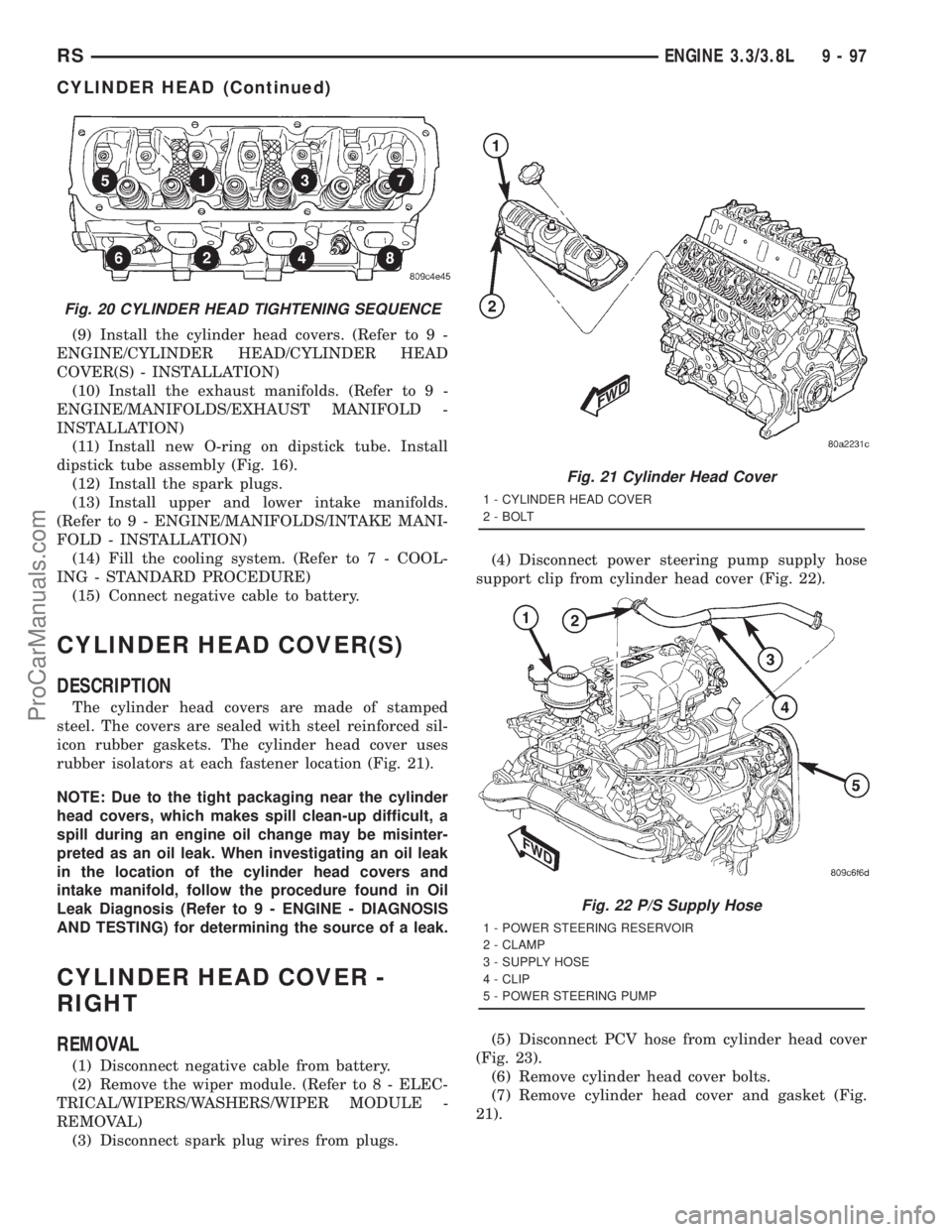
Fig. 20 CYLINDER HEAD TIGHTENING SEQUENCE
Fig. 21 Cylinder Head Cover
1 - CYLINDER HEAD COVER
2 - BOLT
Fig. 22 P/S Supply Hose
1 - POWER STEERING RESERVOIR
2 - CLAMP
3 - SUPPLY HOSE
4 - CLIP
5 - POWER STEERING PUMP
RSENGINE 3.3/3.8L9-97
CYLINDER HEAD (Continued)
ProCarManuals.com
Page 1278 of 2321
STANDARD PROCEDURES - FITTING PISTONS
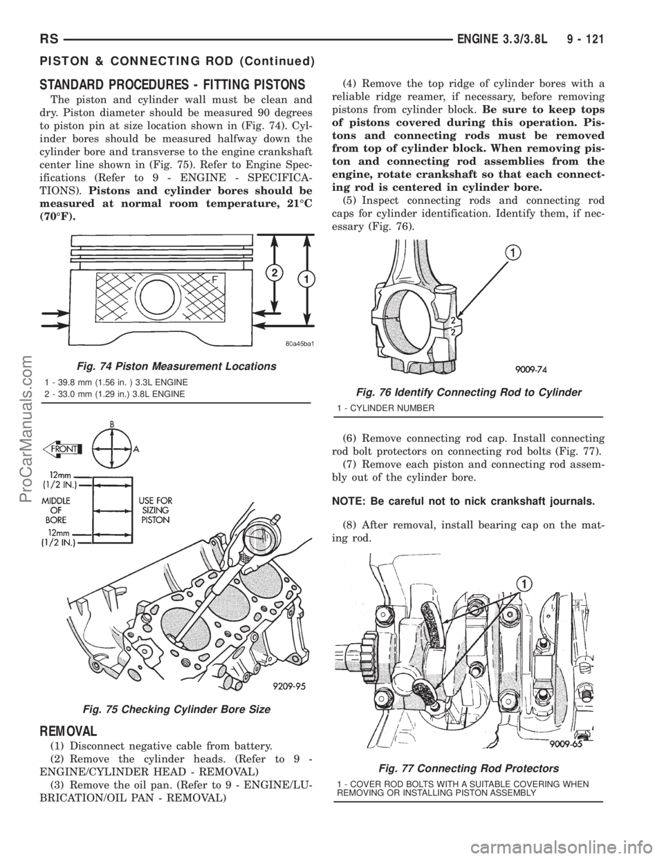
The piston and cylinder wall must be clean and
dry. Piston diameter should be measured 90 degrees
to piston pin at size location shown in (Fig. 74). Cyl-
inder bores should be measured halfway down the
cylinder bore and transverse to the engine crankshaft
center line shown in (Fig. 75). Refer to Engine Spec-
ifications (Refer to 9 - ENGINE - SPECIFICA-
TIONS).Pistons and cylinder bores should be
measured at normal room temperature, 21ÉC
(70ÉF).
REMOVAL
(1) Disconnect negative cable from battery.
(2) Remove the cylinder heads. (Refer to 9 -
ENGINE/CYLINDER HEAD - REMOVAL)
(3) Remove the oil pan. (Refer to 9 - ENGINE/LU-
BRICATION/OIL PAN - REMOVAL)(4) Remove the top ridge of cylinder bores with a
reliable ridge reamer, if necessary, before removing
pistons from cylinder block.Be sure to keep tops
of pistons covered during this operation. Pis-
tons and connecting rods must be removed
from top of cylinder block. When removing pis-
ton and connecting rod assemblies from the
engine, rotate crankshaft so that each connect-
ing rod is centered in cylinder bore.
(5) Inspect connecting rods and connecting rod
caps for cylinder identification. Identify them, if nec-
essary (Fig. 76).
(6) Remove connecting rod cap. Install connecting
rod bolt protectors on connecting rod bolts (Fig. 77).
(7) Remove each piston and connecting rod assem-
bly out of the cylinder bore.
NOTE: Be careful not to nick crankshaft journals.
(8) After removal, install bearing cap on the mat-
ing rod.
Fig. 74 Piston Measurement Locations
1 - 39.8 mm (1.56 in. ) 3.3L ENGINE
2 - 33.0 mm (1.29 in.) 3.8L ENGINE
Fig. 75 Checking Cylinder Bore Size
Fig. 76 Identify Connecting Rod to Cylinder
1 - CYLINDER NUMBER
Fig. 77 Connecting Rod Protectors
1 - COVER ROD BOLTS WITH A SUITABLE COVERING WHEN
REMOVING OR INSTALLING PISTON ASSEMBLY
RSENGINE 3.3/3.8L9 - 121
PISTON & CONNECTING ROD (Continued)
ProCarManuals.com
Page 1294 of 2321
(8) Connect negative cable to battery.
(9) Fill crankcase with oil to proper level.
OIL PRESSURE RELIEF VALVE
REMOVAL
(1) Remove oil pan.
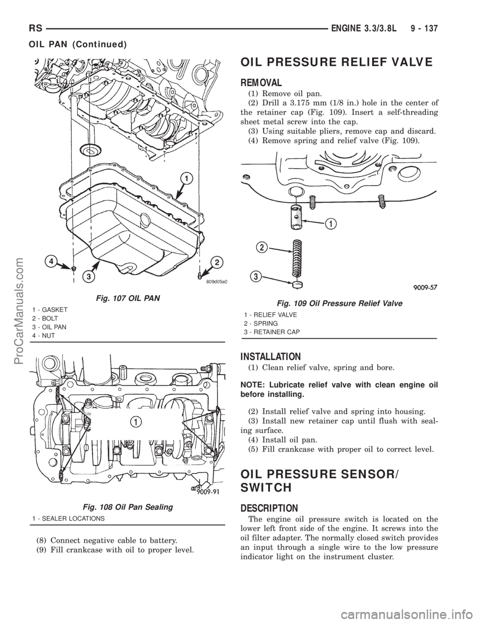
(2) Drill a 3.175 mm (1/8 in.) hole in the center of
the retainer cap (Fig. 109). Insert a self-threading
sheet metal screw into the cap.
(3) Using suitable pliers, remove cap and discard.
(4) Remove spring and relief valve (Fig. 109).
INSTALLATION
(1) Clean relief valve, spring and bore.
NOTE: Lubricate relief valve with clean engine oil
before installing.
(2) Install relief valve and spring into housing.
(3) Install new retainer cap until flush with seal-
ing surface.
(4) Install oil pan.
(5) Fill crankcase with proper oil to correct level.
OIL PRESSURE SENSOR/
SWITCH
DESCRIPTION
The engine oil pressure switch is located on the
lower left front side of the engine. It screws into the
oil filter adapter. The normally closed switch provides
an input through a single wire to the low pressure
indicator light on the instrument cluster.
Fig. 107 OIL PAN
1 - GASKET
2 - BOLT
3 - OIL PAN
4 - NUT
Fig. 108 Oil Pan Sealing
1 - SEALER LOCATIONS
Fig. 109 Oil Pressure Relief Valve
1 - RELIEF VALVE
2 - SPRING
3 - RETAINER CAP
RSENGINE 3.3/3.8L9 - 137
OIL PAN (Continued)
ProCarManuals.com
Page 1300 of 2321
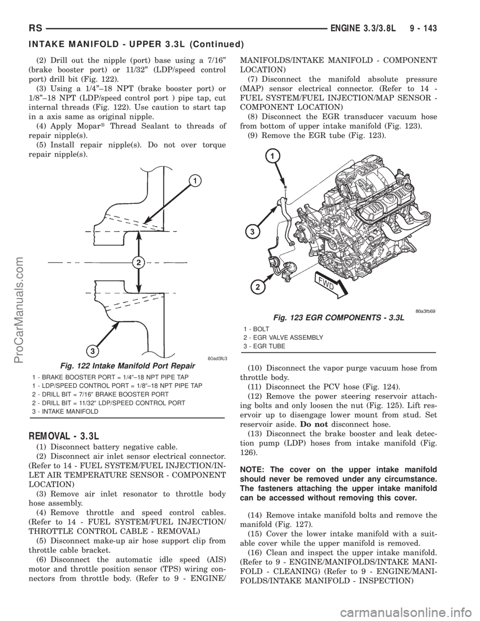
(2) Drill out the nipple (port) base using a 7/16º
(brake booster port) or 11/32º (LDP/speed control
port) drill bit (Fig. 122).
(3) Using a 1/4º±18 NPT (brake booster port) or
1/8º±18 NPT (LDP/speed control port ) pipe tap, cut
internal threads (Fig. 122). Use caution to start tap
in a axis same as original nipple.
(4) Apply MopartThread Sealant to threads of
repair nipple(s).
(5) Install repair nipple(s). Do not over torque
repair nipple(s).
REMOVAL - 3.3L
(1) Disconnect battery negative cable.
(2) Disconnect air inlet sensor electrical connector.
(Refer to 14 - FUEL SYSTEM/FUEL INJECTION/IN-
LET AIR TEMPERATURE SENSOR - COMPONENT
LOCATION)
(3) Remove air inlet resonator to throttle body
hose assembly.
(4) Remove throttle and speed control cables.
(Refer to 14 - FUEL SYSTEM/FUEL INJECTION/
THROTTLE CONTROL CABLE - REMOVAL)
(5) Disconnect make-up air hose support clip from
throttle cable bracket.
(6) Disconnect the automatic idle speed (AIS)
motor and throttle position sensor (TPS) wiring con-
nectors from throttle body. (Refer to 9 - ENGINE/MANIFOLDS/INTAKE MANIFOLD - COMPONENT
LOCATION)
(7) Disconnect the manifold absolute pressure
(MAP) sensor electrical connector. (Refer to 14 -
FUEL SYSTEM/FUEL INJECTION/MAP SENSOR -
COMPONENT LOCATION)
(8) Disconnect the EGR transducer vacuum hose
from bottom of upper intake manifold (Fig. 123).
(9) Remove the EGR tube (Fig. 123).
(10) Disconnect the vapor purge vacuum hose from
throttle body.
(11) Disconnect the PCV hose (Fig. 124).
(12) Remove the power steering reservoir attach-
ing bolts and only loosen the nut (Fig. 125). Lift res-
ervoir up to disengage lower mount from stud. Set
reservoir aside.Do notdisconnect hose.
(13) Disconnect the brake booster and leak detec-
tion pump (LDP) hoses from intake manifold (Fig.
126).
NOTE: The cover on the upper intake manifold
should never be removed under any circumstance.
The fasteners attaching the upper intake manifold
can be accessed without removing this cover.
(14) Remove intake manifold bolts and remove the
manifold (Fig. 127).
(15) Cover the lower intake manifold with a suit-
able cover while the upper manifold is removed.
(16) Clean and inspect the upper intake manifold.
(Refer to 9 - ENGINE/MANIFOLDS/INTAKE MANI-
FOLD - CLEANING) (Refer to 9 - ENGINE/MANI-
FOLDS/INTAKE MANIFOLD - INSPECTION)
Fig. 122 Intake Manifold Port Repair
1 - BRAKE BOOSTER PORT = 1/49±18 NPT PIPE TAP
1 - LDP/SPEED CONTROL PORT = 1/89±18 NPT PIPE TAP
2 - DRILL BIT = 7/169BRAKE BOOSTER PORT
2 - DRILL BIT = 11/329LDP/SPEED CONTROL PORT
3 - INTAKE MANIFOLD
Fig. 123 EGR COMPONENTS - 3.3L
1 - BOLT
2 - EGR VALVE ASSEMBLY
3 - EGR TUBE
RSENGINE 3.3/3.8L9 - 143
INTAKE MANIFOLD - UPPER 3.3L (Continued)
ProCarManuals.com
Page 1302 of 2321
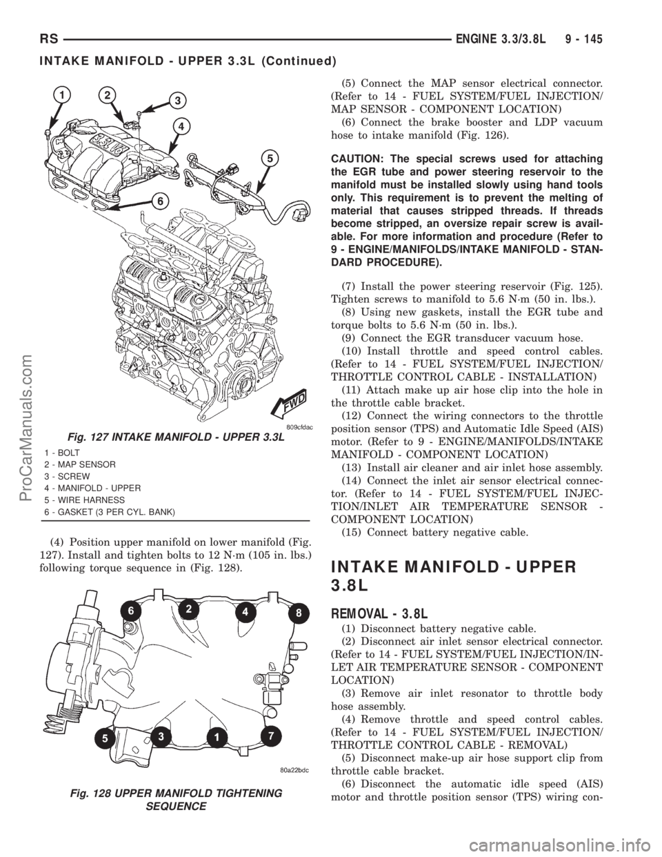
(4) Position upper manifold on lower manifold (Fig.
127). Install and tighten bolts to 12 N´m (105 in. lbs.)
following torque sequence in (Fig. 128).(5) Connect the MAP sensor electrical connector.
(Refer to 14 - FUEL SYSTEM/FUEL INJECTION/
MAP SENSOR - COMPONENT LOCATION)
(6) Connect the brake booster and LDP vacuum
hose to intake manifold (Fig. 126).
CAUTION: The special screws used for attaching
the EGR tube and power steering reservoir to the
manifold must be installed slowly using hand tools
only. This requirement is to prevent the melting of
material that causes stripped threads. If threads
become stripped, an oversize repair screw is avail-
able. For more information and procedure (Refer to
9 - ENGINE/MANIFOLDS/INTAKE MANIFOLD - STAN-
DARD PROCEDURE).
(7) Install the power steering reservoir (Fig. 125).
Tighten screws to manifold to 5.6 N´m (50 in. lbs.).
(8) Using new gaskets, install the EGR tube and
torque bolts to 5.6 N´m (50 in. lbs.).
(9) Connect the EGR transducer vacuum hose.
(10) Install throttle and speed control cables.
(Refer to 14 - FUEL SYSTEM/FUEL INJECTION/
THROTTLE CONTROL CABLE - INSTALLATION)
(11) Attach make up air hose clip into the hole in
the throttle cable bracket.
(12) Connect the wiring connectors to the throttle
position sensor (TPS) and Automatic Idle Speed (AIS)
motor. (Refer to 9 - ENGINE/MANIFOLDS/INTAKE
MANIFOLD - COMPONENT LOCATION)
(13) Install air cleaner and air inlet hose assembly.
(14) Connect the inlet air sensor electrical connec-
tor. (Refer to 14 - FUEL SYSTEM/FUEL INJEC-
TION/INLET AIR TEMPERATURE SENSOR -
COMPONENT LOCATION)
(15) Connect battery negative cable.
INTAKE MANIFOLD - UPPER
3.8L
REMOVAL - 3.8L
(1) Disconnect battery negative cable.
(2) Disconnect air inlet sensor electrical connector.
(Refer to 14 - FUEL SYSTEM/FUEL INJECTION/IN-
LET AIR TEMPERATURE SENSOR - COMPONENT
LOCATION)
(3) Remove air inlet resonator to throttle body
hose assembly.
(4) Remove throttle and speed control cables.
(Refer to 14 - FUEL SYSTEM/FUEL INJECTION/
THROTTLE CONTROL CABLE - REMOVAL)
(5) Disconnect make-up air hose support clip from
throttle cable bracket.
(6) Disconnect the automatic idle speed (AIS)
motor and throttle position sensor (TPS) wiring con-
Fig. 127 INTAKE MANIFOLD - UPPER 3.3L
1 - BOLT
2 - MAP SENSOR
3 - SCREW
4 - MANIFOLD - UPPER
5 - WIRE HARNESS
6 - GASKET (3 PER CYL. BANK)
Fig. 128 UPPER MANIFOLD TIGHTENING
SEQUENCE
RSENGINE 3.3/3.8L9 - 145
INTAKE MANIFOLD - UPPER 3.3L (Continued)
ProCarManuals.com
Page 1305 of 2321
(11) Install throttle and speed control cables.
(Refer to 14 - FUEL SYSTEM/FUEL INJECTION/
THROTTLE CONTROL CABLE - INSTALLATION)
(12) Attach make up air hose clip into the hole in
the throttle cable bracket.
(13) Connect the vapor purge vacuum hose to
throttle body.
(14) Connect the wiring connectors to the throttle
position sensor (TPS) and Automatic Idle Speed (AIS)
motor. (Refer to 9 - ENGINE/MANIFOLDS/INTAKE
MANIFOLD - COMPONENT LOCATION)
(15) Install air cleaner and air inlet hose assembly.
(16) Connect the inlet air sensor electrical connec-
tor. (Refer to 14 - FUEL SYSTEM/FUEL INJEC-
TION/INLET AIR TEMPERATURE SENSOR -
COMPONENT LOCATION)
(17) Connect battery negative cable.
INTAKE MANIFOLD - LOWER
REMOVAL
(1) Perform fuel system pressure release procedure
(before attempting any repairs).(Refer to 14 -
FUEL SYSTEM/FUEL DELIVERY - STANDARD
PROCEDURE)
(2) Drain the cooling system. (Refer to 7 - COOL-
ING - STANDARD PROCEDURE)
(3) Remove the upper intake manifold. (Refer to 9
- ENGINE/MANIFOLDS/INTAKE MANIFOLD -
REMOVAL)
(4) Remove the fuel line. (Refer to 14 - FUEL SYS-
TEM/FUEL DELIVERY/FUEL LINES - STANDARD
PROCEDURE) (Refer to 14 - FUEL SYSTEM/FUEL
DELIVERY/QUICK CONNECT FITTING - STAN-
DARD PROCEDURE)
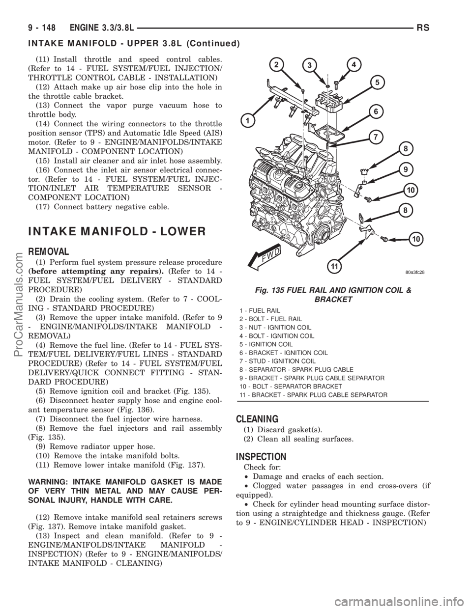
(5) Remove ignition coil and bracket (Fig. 135).
(6) Disconnect heater supply hose and engine cool-
ant temperature sensor (Fig. 136).
(7) Disconnect the fuel injector wire harness.
(8) Remove the fuel injectors and rail assembly
(Fig. 135).
(9) Remove radiator upper hose.
(10) Remove the intake manifold bolts.
(11) Remove lower intake manifold (Fig. 137).
WARNING: INTAKE MANIFOLD GASKET IS MADE
OF VERY THIN METAL AND MAY CAUSE PER-
SONAL INJURY, HANDLE WITH CARE.
(12) Remove intake manifold seal retainers screws
(Fig. 137). Remove intake manifold gasket.
(13) Inspect and clean manifold. (Refer to 9 -
ENGINE/MANIFOLDS/INTAKE MANIFOLD -
INSPECTION) (Refer to 9 - ENGINE/MANIFOLDS/
INTAKE MANIFOLD - CLEANING)
CLEANING
(1) Discard gasket(s).
(2) Clean all sealing surfaces.
INSPECTION
Check for:
²Damage and cracks of each section.
²Clogged water passages in end cross-overs (if
equipped).
²Check for cylinder head mounting surface distor-
tion using a straightedge and thickness gauge. (Refer
to 9 - ENGINE/CYLINDER HEAD - INSPECTION)
Fig. 135 FUEL RAIL AND IGNITION COIL &
BRACKET
1 - FUEL RAIL
2 - BOLT - FUEL RAIL
3 - NUT - IGNITION COIL
4 - BOLT - IGNITION COIL
5 - IGNITION COIL
6 - BRACKET - IGNITION COIL
7 - STUD - IGNITION COIL
8 - SEPARATOR - SPARK PLUG CABLE
9 - BRACKET - SPARK PLUG CABLE SEPARATOR
10 - BOLT - SEPARATOR BRACKET
11 - BRACKET - SPARK PLUG CABLE SEPARATOR
9 - 148 ENGINE 3.3/3.8LRS
INTAKE MANIFOLD - UPPER 3.8L (Continued)
ProCarManuals.com
Page 1306 of 2321
INSTALLATION
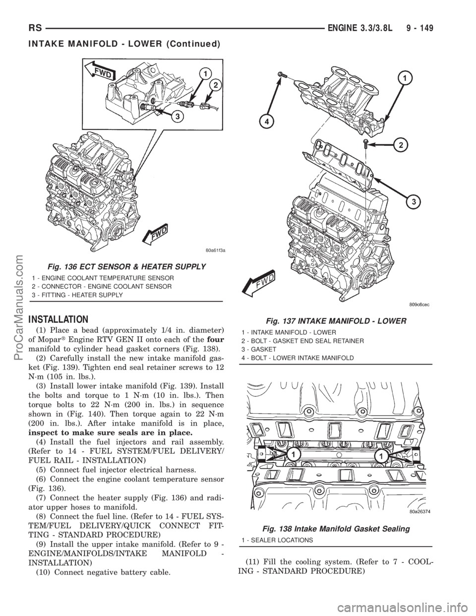
(1) Place a bead (approximately 1/4 in. diameter)
of MopartEngine RTV GEN II onto each of thefour
manifold to cylinder head gasket corners (Fig. 138).
(2) Carefully install the new intake manifold gas-
ket (Fig. 139). Tighten end seal retainer screws to 12
N´m (105 in. lbs.).
(3) Install lower intake manifold (Fig. 139). Install
the bolts and torque to 1 N´m (10 in. lbs.). Then
torque bolts to 22 N´m (200 in. lbs.) in sequence
shown in (Fig. 140). Then torque again to 22 N´m
(200 in. lbs.). After intake manifold is in place,
inspect to make sure seals are in place.
(4) Install the fuel injectors and rail assembly.
(Refer to 14 - FUEL SYSTEM/FUEL DELIVERY/
FUEL RAIL - INSTALLATION)
(5) Connect fuel injector electrical harness.
(6) Connect the engine coolant temperature sensor
(Fig. 136).
(7) Connect the heater supply (Fig. 136) and radi-
ator upper hoses to manifold.
(8) Connect the fuel line. (Refer to 14 - FUEL SYS-
TEM/FUEL DELIVERY/QUICK CONNECT FIT-
TING - STANDARD PROCEDURE)
(9) Install the upper intake manifold. (Refer to 9 -
ENGINE/MANIFOLDS/INTAKE MANIFOLD -
INSTALLATION)
(10) Connect negative battery cable.(11) Fill the cooling system. (Refer to 7 - COOL-
ING - STANDARD PROCEDURE)
Fig. 136 ECT SENSOR & HEATER SUPPLY
1 - ENGINE COOLANT TEMPERATURE SENSOR
2 - CONNECTOR - ENGINE COOLANT SENSOR
3 - FITTING - HEATER SUPPLY
Fig. 137 INTAKE MANIFOLD - LOWER
1 - INTAKE MANIFOLD - LOWER
2 - BOLT - GASKET END SEAL RETAINER
3 - GASKET
4 - BOLT - LOWER INTAKE MANIFOLD
Fig. 138 Intake Manifold Gasket Sealing
1 - SEALER LOCATIONS
RSENGINE 3.3/3.8L9 - 149
INTAKE MANIFOLD - LOWER (Continued)
ProCarManuals.com
Page 1313 of 2321
TIMING CHAIN AND
SPROCKETS
REMOVAL - TIMING CHAIN AND CAMSHAFT
SPROCKET
(1) Disconnect negative cable from battery.
(2) Remove the timing chain cover. (Refer to 9 -
ENGINE/VALVE TIMING/TIMING BELT / CHAIN
COVER(S) - REMOVAL)
(3) Rotate engine by turning crankshaft until the
timing marks are aligned as shown in (Fig. 156).
(4) Remove camshaft sprocket attaching bolt.
(5) Remove the timing chain with camshaft
sprocket.
(6) Remove the crankshaft sprocket. (Refer to 9 -
ENGINE/VALVE TIMING/TIMING BELT/CHAIN
AND SPROCKETS - REMOVAL)
REMOVAL - CRANKSHAFT SPROCKET
(1) Remove the timing chain. (Refer to 9 -
ENGINE/VALVE TIMING/TIMING BELT/CHAIN
AND SPROCKETS - REMOVAL)
(2) Using Special Tools 8539, 5048-6, and 5048-1,
remove the crankshaft sprocket while holding the
crankshaft from turning (Fig. 157). Be careful not to
damage the crankshaft surfaces.
INSPECTION
(1) Position a scale next to timing chain so that
any movement of chain may be measured.
(2) Position a torque wrench and socket on the
camshaft sprocket attaching bolt. Apply force in the
direction of crankshaft rotation to take up slack to
the following torque:
²41 N´m (30 ft. lb.) with cylinder heads installed
²20 N´m (15 ft. lb.) with cylinder heads removed
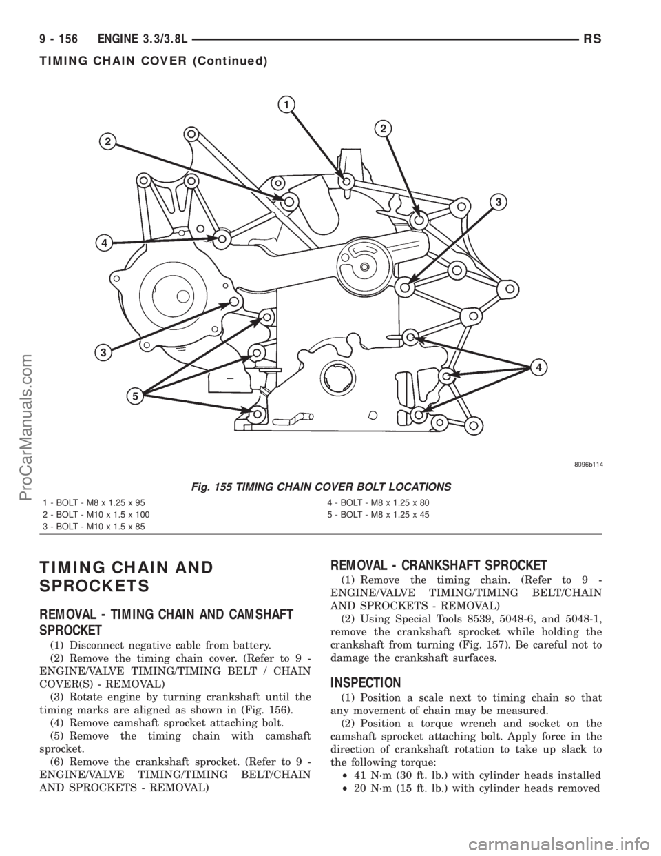
Fig. 155 TIMING CHAIN COVER BOLT LOCATIONS
1 - BOLT - M8 x 1.25 x 95 4 - BOLT - M8 x 1.25 x 80
2 - BOLT - M10 x 1.5 x 100 5 - BOLT - M8 x 1.25 x 45
3 - BOLT - M10 x 1.5 x 85
9 - 156 ENGINE 3.3/3.8LRS
TIMING CHAIN COVER (Continued)
ProCarManuals.com