2001 DODGE RAM radio
[x] Cancel search: radioPage 1098 of 2889
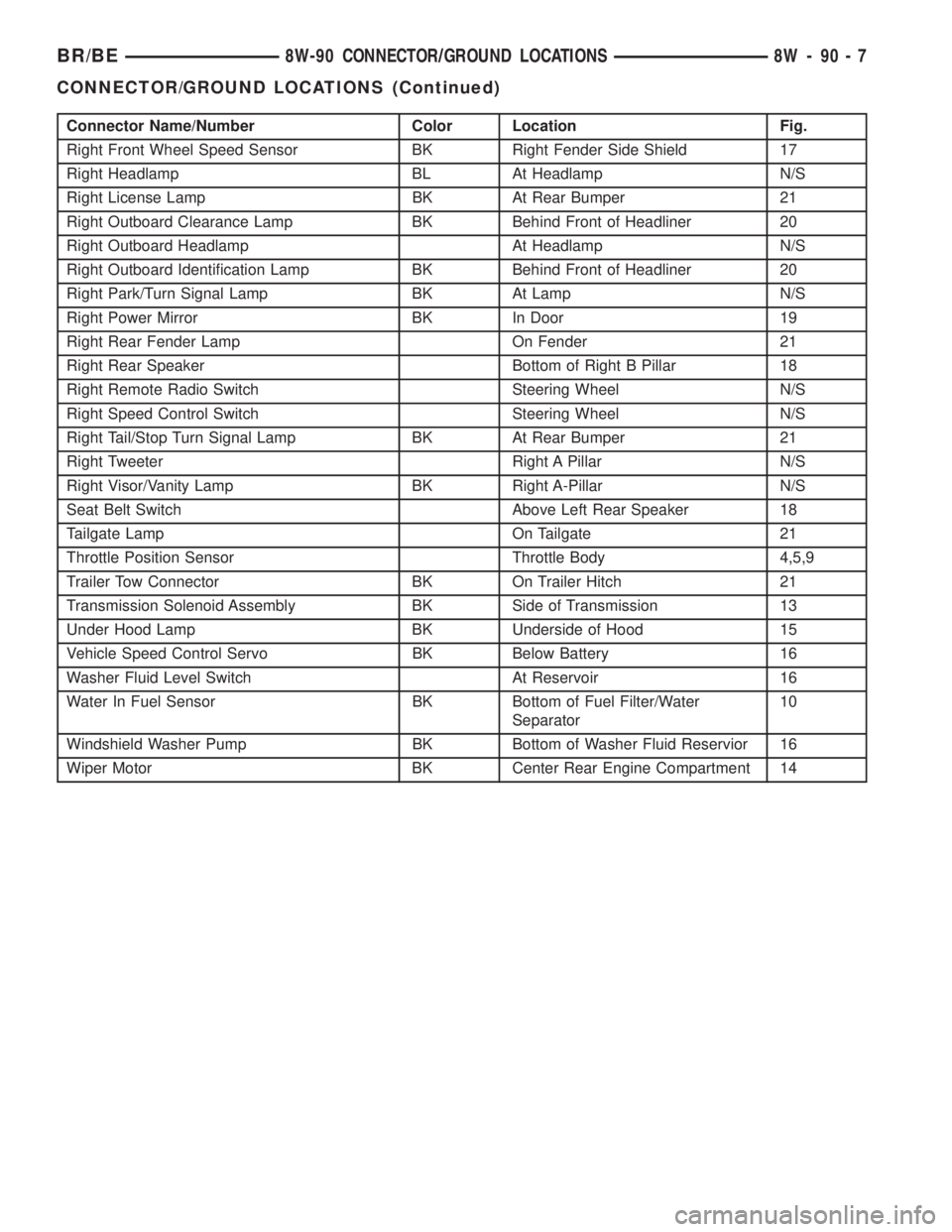
Connector Name/Number Color Location Fig.
Right Front Wheel Speed Sensor BK Right Fender Side Shield 17
Right Headlamp BL At Headlamp N/S
Right License Lamp BK At Rear Bumper 21
Right Outboard Clearance Lamp BK Behind Front of Headliner 20
Right Outboard Headlamp At Headlamp N/S
Right Outboard Identification Lamp BK Behind Front of Headliner 20
Right Park/Turn Signal Lamp BK At Lamp N/S
Right Power Mirror BK In Door 19
Right Rear Fender Lamp On Fender 21
Right Rear Speaker Bottom of Right B Pillar 18
Right Remote Radio Switch Steering Wheel N/S
Right Speed Control Switch Steering Wheel N/S
Right Tail/Stop Turn Signal Lamp BK At Rear Bumper 21
Right Tweeter Right A Pillar N/S
Right Visor/Vanity Lamp BK Right A-Pillar N/S
Seat Belt Switch Above Left Rear Speaker 18
Tailgate Lamp On Tailgate 21
Throttle Position Sensor Throttle Body 4,5,9
Trailer Tow Connector BK On Trailer Hitch 21
Transmission Solenoid Assembly BK Side of Transmission 13
Under Hood Lamp BK Underside of Hood 15
Vehicle Speed Control Servo BK Below Battery 16
Washer Fluid Level Switch At Reservoir 16
Water In Fuel Sensor BK Bottom of Fuel Filter/Water
Separator10
Windshield Washer Pump BK Bottom of Washer Fluid Reservior 16
Wiper Motor BK Center Rear Engine Compartment 14
BR/BE8W-90 CONNECTOR/GROUND LOCATIONS 8W - 90 - 7
CONNECTOR/GROUND LOCATIONS (Continued)
Page 1125 of 2889
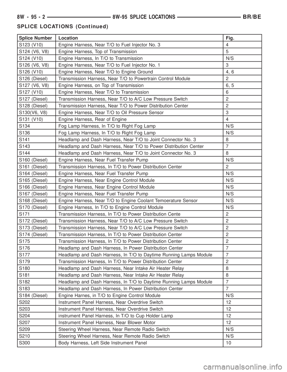
Splice Number Location Fig.
S123 (V10) Engine Harness, Near T/O to Fuel Injector No. 3 4
S124 (V6, V8) Engine Harness, Top of Transmission 5
S124 (V10) Engine Harness, In T/O to Transmission N/S
S126 (V6, V8) Engine Harness, Near T/O to Fuel Injector No. 1 3
S126 (V10) Engine Harness, Near T/O to Engine Ground 4, 6
S126 (Diesel) Transmission Harness, Near T/O to Powertrain Control Module 2
S127 (V6, V8) Engine Harness, on Top of Transmission 6, 5
S127 (V10) Engine Harness, Near T/O to Transmission 6
S127 (Diesel) Transmission Harness, Near T/O to A/C Low Pressure Switch 2
S128 (Diesel) Transmission Harness, Near T/O to Power Distribution Center 2
S130(V6, V8) Engine Harness, Near T/O to Oil Pressure Sensor 3
S131 (V10) Engine Harness, Rear of Engine 4
S134 Fog Lamp Harness, In T/O to Right Fog Lamp N/S
S136 Fog Lamp Harness, In T/O to Right Fog Lamp N/S
S141 Headlamp and Dash Harness, Near T/O to Joint Connector No. 3 8
S143 Headlamp and Dash Harness, Near T/O to Power Distribution Center 7
S144 Headlamp and Dash Harness, Near T/O to Joint Connector No. 3 8
S160 (Diesel) Engine Harness, Near Fuel Transfer Pump N/S
S161 (Diesel) Transmission Harness, In T/O to Power Distribution Center 2
S164 (Diesel) Engine Harness, Near Fuel Transfer Pump N/S
S165 (Diesel) Engine Harness, Near Engine Control Module N/S
S166 (Diesel) Engine Harness, Near Engine Control Module N/S
S167 (Diesel) Engine Harness, Near Fuel Transfer Pump N/S
S168 (Diesel) Engine Harness, Near T/O to Engine Coolant Temoerature Sensor N/S
S170 (Diesel) Engine Harness, In T/O to Engine Control Module N/S
S171 Transmission Harness, In T/O to Power Distribution Cente 2
S172 (Diesel) Transmission Harness, Near T/O to A/C Low Pressure Switch 2
S173 (Diesel) Transmission Harness, Near T/O to A/C Low Pressure Switch 2
S174 (Diesel) Transmission Harness, In T/O to Power Distribution Center 2
S175 Transmission Harness, In T/O to Power Distribution Center 2
S176 Headlamp and Dash Harness, In Power Distribution Center 7
S177 Headlamp and Dash Harness, In T/O to Daytime Running Lamps Module 7
S179 Transmission Harness, In T/O to Power Distribution Center 2
S180 Headlamp and Dash Harness, Near Intake Air Heater Relay 8
S181 Headlamp and Dash Harness, Near Intake Air Heater Relay 8
S182 Headlamp and Dash Harness, In T/O to Daytime Running Lamps Module 7
S183 Headlamp and Dash Harness, In Power Distribution Center 7
S184 (Diesel) Engine Harnes, in T/O to Engine Control Module N/S
S202 Instrument Panel Harness, Near Overdrive Switch 12
S203 Instrument Panel Harness, Near Overdrive Switch 12
S204 instrument Panel Harness, In T/O to Cup Holder Lamp 12
S207 Instrument Panel Harness, Near Blower Motor 12
S209 Steering Wheel Harness, Near Remote Radio Switch N/S
S210 Steering Wheel Harness, Near Remote Radio Switch N/S
S300 Body Harness, Left Side Instrument Panel 10
8W - 95 - 2 8W-95 SPLICE LOCATIONSBR/BE
SPLICE LOCATIONS (Continued)
Page 1137 of 2889
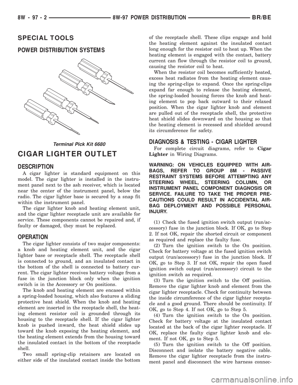
SPECIAL TOOLS
POWER DISTRIBUTION SYSTEMS
CIGAR LIGHTER OUTLET
DESCRIPTION
A cigar lighter is standard equipment on this
model. The cigar lighter is installed in the instru-
ment panel next to the ash receiver, which is located
near the center of the instrument panel, below the
radio. The cigar lighter base is secured by a snap fit
within the instrument panel.
The cigar lighter knob and heating element unit,
and the cigar lighter receptacle unit are available for
service. These components cannot be repaired and, if
faulty or damaged, they must be replaced.
OPERATION
The cigar lighter consists of two major components:
a knob and heating element unit, and the cigar
lighter base or receptacle shell. The receptacle shell
is connected to ground, and an insulated contact in
the bottom of the shell is connected to battery cur-
rent. The cigar lighter receives battery voltage from a
fuse in the junction block only when the ignition
switch is in the Accessory or On positions.
The knob and heating element are encased within
a spring-loaded housing, which also features a sliding
protective heat shield. When the knob and heating
element are inserted in the receptacle shell, the heat-
ing element resistor coil is grounded through its
housing to the receptacle shell. If the cigar lighter
knob is pushed inward, the heat shield slides up
toward the knob exposing the heating element, and
the heating element extends from the housing toward
the insulated contact in the bottom of the receptacle
shell.
Two small spring-clip retainers are located on
either side of the insulated contact inside the bottomof the receptacle shell. These clips engage and hold
the heating element against the insulated contact
long enough for the resistor coil to heat up. When the
heating element is engaged with the contact, battery
current can flow through the resistor coil to ground,
causing the resistor coil to heat.
When the resistor coil becomes sufficiently heated,
excess heat radiates from the heating element caus-
ing the spring-clips to expand. Once the spring-clips
expand far enough to release the heating element,
the spring-loaded housing forces the knob and heat-
ing element to pop back outward to their relaxed
position. When the cigar lighter knob and element
are pulled out of the receptacle shell, the protective
heat shield slides downward on the housing so that
the heating element is recessed and shielded around
its circumference for safety.
DIAGNOSIS & TESTING - CIGAR LIGHTER
For complete circuit diagrams, refer toCigar
Lighterin Wiring Diagrams.
WARNING: ON VEHICLES EQUIPPED WITH AIR-
BAGS, REFER TO GROUP 8M - PASSIVE
RESTRAINT SYSTEMS BEFORE ATTEMPTING ANY
STEERING WHEEL, STEERING COLUMN, OR
INSTRUMENT PANEL COMPONENT DIAGNOSIS OR
SERVICE. FAILURE TO TAKE THE PROPER PRE-
CAUTIONS COULD RESULT IN ACCIDENTAL AIR-
BAG DEPLOYMENT AND POSSIBLE PERSONAL
INJURY.
(1) Check the fused ignition switch output (run/ac-
cessory) fuse in the junction block. If OK, go to Step
2. If not OK, repair the shorted circuit or component
as required and replace the faulty fuse.
(2) Turn the ignition switch to the On position.
Check for battery voltage at the fused ignition switch
output (run/accessory) fuse in the junction block. If
OK, go to Step 3. If not OK, repair the open fused
ignition switch output (run/accessory) circuit to the
ignition switch as required.
(3) Turn the ignition switch to the Off position.
Remove the cigar lighter knob and element from the
cigar lighter receptacle. Check for continuity between
the inside circumference of the cigar lighter recepta-
cle and a good ground. There should be continuity. If
OK, go to Step 4. If not OK, go to Step 5.
(4) Turn the ignition switch to the On position.
Check for battery voltage at the insulated contact
located at the back of the cigar lighter receptacle. If
OK, replace the faulty cigar lighter knob and ele-
ment. If not OK, go to Step 5.
(5) Turn the ignition switch to the Off position.
Disconnect and isolate the battery negative cable.
Remove the cigar lighter receptacle from the instru-
ment panel and disconnect the wire harness connec-Terminal Pick Kit 6680
8W - 97 - 2 8W-97 POWER DISTRIBUTIONBR/BE
Page 1145 of 2889
the instrument panel, below the radio. The power
outlet base is secured by a snap fit within the instru-
ment panel. A plastic protective cap snaps into the
power outlet base when the power outlet is not being
used, and hangs from the power outlet base mount
by an integral bail strap while the power outlet is in
use.
The power outlet receptacle unit and the accessory
power outlet protective cap are available for service.
The power outlet receptacle cannot be repaired and,
if faulty or damaged, it must be replaced.
OPERATION
The power outlet base or receptacle shell is con-
nected to ground, and an insulated contact in the
bottom of the shell is connected to battery current.
The power outlet receives battery voltage from a fuse
in the Power Distribution Center (PDC) at all times.
While the power outlet is very similar to a cigar
lighter base unit, it does not include the two small
spring-clip retainers inside the bottom of the recepta-
cle shell that are used to secure the cigar lighter
heating element to the insulated contact.
DIAGNOSIS & TESTING - POWER OUTLET
For complete circuit diagrams, refer toPower
Outletin Wiring Diagrams.
WARNING: ON VEHICLES EQUIPPED WITH AIR-
BAGS, REFER TO GROUP 8M - PASSIVE
RESTRAINT SYSTEMS BEFORE ATTEMPTING ANY
STEERING WHEEL, STEERING COLUMN, OR
INSTRUMENT PANEL COMPONENT DIAGNOSIS OR
SERVICE. FAILURE TO TAKE THE PROPER PRE-
CAUTIONS COULD RESULT IN ACCIDENTAL AIR-
BAG DEPLOYMENT AND POSSIBLE PERSONAL
INJURY.
(1) Check the fused B(+) fuse in the Power Distri-
bution Center (PDC). If OK, go to Step 2. If not OK,
repair the shorted circuit or component as required
and replace the faulty fuse.
(2) Check for battery voltage at the fused B(+) fuse
in the PDC. If OK, go to Step 3. If not OK, repair the
open fused B(+) circuit to the battery as required.
(3) Remove the plastic protective cap from the
power outlet receptacle. Check for continuity between
the inside circumference of the power outlet recepta-
cle and a good ground. There should be continuity. If
OK, go to Step 4. If not OK, go to Step 5.
(4) Check for battery voltage at the insulated con-
tact located at the back of the power outlet recepta-
cle. If not OK, go to Step 5.
(5) Disconnect and isolate the battery negative
cable. Remove the power outlet receptacle from the
instrument panel. Disconnect the wire harness con-
nector from the power outlet receptacle. Check forcontinuity between the ground circuit cavity of the
power outlet wire harness connector and a good
ground. There should be continuity. If OK, go to Step
6. If not OK, repair the open ground circuit to ground
as required.
(6) Connect the battery negative cable. Check for
battery voltage at the fused B(+) circuit cavity of the
power outlet wire harness connector. If OK, replace
the faulty power outlet receptacle. If not OK, repair
the open fused B(+) circuit to the PDC fuse as
required.
REMOVAL
(1) Disconnect and isolate the battery negative
cable.
(2) Pull the cigar lighter knob and element out of
the cigar lighter receptacle base, or unsnap the pro-
tective cap from the power outlet receptacle base
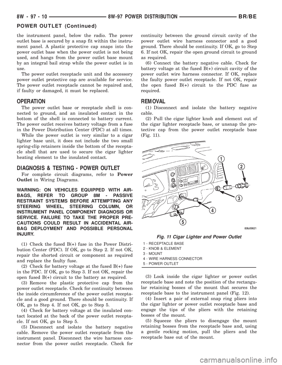
(Fig. 11).
(3) Look inside the cigar lighter or power outlet
receptacle base and note the position of the rectangu-
lar retaining bosses of the mount that secures the
receptacle base to the instrument panel (Fig. 12).
(4) Insert a pair of external snap ring pliers into
the cigar lighter or power outlet receptacle base and
engage the tips of the pliers with the retaining
bosses of the mount.
(5) Squeeze the pliers to disengage the mount
retaining bosses from the receptacle base and, using
a gentle rocking motion, pull the pliers and the
receptacle base out of the mount.
Fig. 11 Cigar Lighter and Power Outlet
1 - RECEPTACLE BASE
2 - KNOB & ELEMENT
3 - MOUNT
4 - WIRE HARNESS CONNECTOR
5 - POWER OUTLET
8W - 97 - 10 8W-97 POWER DISTRIBUTIONBR/BE
POWER OUTLET (Continued)
Page 2677 of 2889
INSTRUMENT PANEL SYSTEM
TABLE OF CONTENTS
page page
INSTRUMENT PANEL SYSTEM
DESCRIPTION..........................104
OPERATION............................105
REMOVAL.............................106
INSTALLATION..........................107
ASH RECEIVER
REMOVAL.............................108
INSTALLATION..........................109
CLUSTER BEZEL
REMOVAL.............................109
INSTALLATION..........................110
CUBBY BIN
REMOVAL.............................110
INSTALLATION..........................110
CUP HOLDER
REMOVAL.............................110
INSTALLATION..........................111
GLOVE BOX
REMOVAL.............................112DISASSEMBLY..........................112
ASSEMBLY.............................112
INSTALLATION..........................113
GLOVE BOX LATCH STRIKER
REMOVAL.............................113
INSTALLATION..........................113
GLOVE BOX OPENING UPPER TRIM
REMOVAL.............................114
INSTALLATION..........................114
INSTRUMENT PANEL TOP COVER
REMOVAL.............................114
INSTALLATION..........................115
STEERING COLUMN OPENING COVER
REMOVAL.............................115
INSTALLATION..........................116
STORAGE BIN
REMOVAL.............................116
INSTALLATION..........................116
INSTRUMENT PANEL SYSTEM
DESCRIPTION
The instrument panel is located at the front of the
passenger compartment. This instrument panel is
molded from a blend of various plastics that are
mechanically attached to the vehicle. Colors are
molded into the plastic components to minimize
appearance degradation from scratches or abrasions.
The panel components are internally ribbed and riv-
eted to steel reinforcements for additional structural
integrity and dimensional stability. The instrument
panel surface components are designed to deform
upon impact without breaking. This type of construc-
tion provides improved energy absorption which, in
conjunction with the dual airbags and seat belts,
helps to improve occupant protection.
The top of the instrument panel is secured to the
top of the dash panel near the base of the windshield
using screws. An end bracket integral to each end of
the instrument panel structure is secured to each
cowl side inner panel with a screw. A stamped metal
bracket supports the center of the instrument panel
by securing it to the top of the floor panel transmis-
sion tunnel below the instrument panel with screws.
The instrument cluster, radio, heater-air conditioner
control, passenger airbag, glove box, electrical junc-
tion block, Central Timer Module (CTM), accessoryswitches, ash receiver, cigar lighter, accessory power
outlet, park brake release handle, inside hood release
handle, as well as numerous other components are
secured to and supported by this unit.
The instrument panel for this vehicle includes the
following major features:
²Cluster Bezel- This molded plastic bezel is
secured with snap clips to the instrument panel sup-
porting structure. It trims out the edges of the head-
lamp switch, instrument cluster, radio, heater-air
conditioner controls, passenger airbag on-off switch,
and the heated seat switches on vehicles so equipped.
On vehicles without the heated seat option, a small
storage cubby bin is provided in the cluster bezel.
This bezel also incorporates three completely adjust-
able panel outlets for the climate control system, and
fills the opening between the instrument cluster and
the top of the steering column where it passes
through the instrument panel.
²Cup Holder/Storage Bin- Vehicles equipped
with an automatic transmission feature a latching
fold-down, adjustable cup holder located on the lower
instrument panel between the glove box and the ash
receiver. Vehicles equipped with a manual transmis-
sion have a lighted storage bin on the instrument
panel in place of the cup holder.
²Glove Box- The hinged bin-type glove box in
the passenger side of the instrument panel features a
recessed paddle-operated latch handle. Three molded
23 - 104 INSTRUMENT PANEL SYSTEMBR/BE
Page 2678 of 2889
hook formations on the lower edge of the glove box
door are engaged with and pivot on three hinge pins
integral to the lower edge of the instrument panel
support structure. The glove box door also serves as
the passenger side knee blocker. A honeycomb struc-
ture between the inner and outer glove box door pan-
els helps to absorb the impact load and distribute it
to the instrument panel structure.
²Steering Column Opening Cover- The steer-
ing column opening cover serves as the driver side
knee blocker. This molded plastic cover has an inte-
gral ribbed plastic liner concealed behind it, for
increased strength and integrity. The steering column
opening cover transfers impact loads to the instru-
ment panel structural support.
²Top Cover- The instrument panel top cover or
base trim is the molded, grained, and color impreg-
nated plastic outer skin of the instrument panel
structural support.
Hard wired circuitry connects the electrical compo-
nents on the instrument panel to each other through
the electrical system of the vehicle. These hard wired
circuits are integral to several wire harnesses, which
are routed throughout the vehicle and retained by
many different methods. These circuits may be con-
nected to each other, to the vehicle electrical system
and to the instrument panel components through the
use of a combination of soldered splices, splice block
connectors and many different types of wire harness
terminal connectors and insulators. Refer to the
appropriate wiring information. The wiring informa-
tion includes complete circuit diagrams, proper wire
and connector repair procedures, further details on
wire harness routing and retention, as well as pin-
out and location views for the various wire harness
connectors, splices, and grounds.
OPERATION
The instrument panel serves as the command cen-
ter of the vehicle, which necessarily makes it a very
complex unit. The instrument panel is designed to
house the controls and monitors for standard and
optional powertrains, climate control systems, audio
systems, safety systems, and many other comfort or
convenience items. When the components of the
instrument panel structural support are properly
assembled and secured in the vehicle they provide
superior instrument panel stiffness and integrity to
help reduce buzzes, squeaks, and rattles. This type of
construction also provides improved energy absorp-
tion which, in conjunction with the dual airbags and
seat belts, helps to improve occupant protection.
The instrument panel is also designed so that all of
the various controls can be safely reached and the
monitors can be easily viewed by the vehicle operator
when driving, while still allowing relative ease ofaccess to each of these items for service. Modular
instrument panel construction allows all of the
gauges and controls to be serviced from the front of
the panel. In addition, most of the instrument panel
electrical components can be accessed without com-
plete instrument panel removal. However, if neces-
sary, the instrument panel can be removed from the
vehicle as an assembly.
The steering column opening cover with its inte-
gral knee blocker located on the driver side of the
instrument panel works in conjunction with the air-
bag system in a frontal vehicle impact to keep the
driver properly positioned for an airbag deployment.
In addition, removal of this component provides
access to the steering column mounts, the steering
column wiring, the Junction Block (JB) (removal of a
snap-fit fuse access panel on the left end of the
instrument panel allows access to the fuses and cir-
cuit breakers), the Central Timer Module (CTM), the
Infinity speaker filter choke and relay unit, much of
the instrument panel wiring, and the gear selector
indicator cable (automatic transmission).
In a frontal collision, the glove box door on the pas-
senger side of the instrument panel provides the
same function for the front seat passenger as the
knee blocker does for the driver. The glove box door
also incorporates a recessed latch handle. Removal of
the glove box provides access to the passenger airbag,
the glove box lamp and switch, the radio antenna
coaxial cable, the heating and air conditioning vac-
uum harness connector, and additional instrument
panel wiring.
Removal of the instrument panel cluster bezel
allows access to the headlamp switch, instrument
cluster, radio, passenger airbag on-off switch, heated
seat switches (if equipped), and the heating and air
conditioning control. Removal of the instrument clus-
ter allows access to the cluster illumination and indi-
cator bulbs, and more of the instrument panel
wiring. Complete instrument panel removal is
required for service of most components internal to
the heating and air conditioning system housing,
including the heater core and the evaporator.
See the owner's manual in the vehicle glove box for
more information on the features, use and operation
of all of the components and systems mounted on or
in the instrument panel.
BR/BEINSTRUMENT PANEL SYSTEM 23 - 105
INSTRUMENT PANEL SYSTEM (Continued)
Page 2679 of 2889
REMOVAL
WARNING: ON VEHICLES EQUIPPED WITH AIR-
BAGS, DISABLE THE AIRBAG SYSTEM BEFORE
ATTEMPTING ANY STEERING WHEEL, STEERING
COLUMN, OR INSTRUMENT PANEL COMPONENT
DIAGNOSIS OR SERVICE. DISCONNECT AND ISO-
LATE THE BATTERY NEGATIVE (GROUND) CABLE,
THEN WAIT TWO MINUTES FOR THE AIRBAG SYS-
TEM CAPACITOR TO DISCHARGE BEFORE PER-
FORMING FURTHER DIAGNOSIS OR SERVICE. THIS
IS THE ONLY SURE WAY TO DISABLE THE AIRBAG
SYSTEM. FAILURE TO TAKE THE PROPER PRE-
CAUTIONS COULD RESULT IN ACCIDENTAL AIR-
BAG DEPLOYMENT AND POSSIBLE PERSONAL
INJURY.
NOTE: Before starting this procedure, be certain to
turn the steering wheel until the front wheels are in
the straight-ahead position.
(1) Disconnect and isolate the battery negative
cable.
(2) Remove the Airbag Control Module (ACM) and
bracket from the floor panel transmission tunnel.
(Refer to 8 - ELECTRICAL/RESTRAINTS/AIRBAG
CONTROL MODULE - REMOVAL).
(3) Remove the trim from the left and right cowl
side inner panels. (Refer to 23 - BODY/INTERIOR/
COWL TRIM COVER - REMOVAL).
(4) Remove the steering column opening cover
from the instrument panel. (Refer to 23 - BODY/IN-
STRUMENT PANEL/STEERING COLUMN OPEN-
ING COVER - REMOVAL).
(5) Remove the two screws that secure the inside
hood latch release handle to the instrument panel
lower reinforcement and lower the release handle to
the floor.
(6) Disconnect the clockspring pigtail wire connec-
tor from the instrument panel wire harness connec-
tor located on the instrument panel lower
reinforcement.
(7) If the vehicle is so equipped, disconnect the
overdrive lockout switch pigtail wire connector from
the instrument panel wire harness connector near
the instrument panel lower reinforcement.
(8) Remove the steering column from the vehicle,
but do not remove the driver airbag, the steering
wheel, or the switches from the column. Be certain
that the steering wheel is locked and secured from
rotation to prevent the loss of clockspring centering.
(Refer to 19 - STEERING/COLUMN - REMOVAL).
(9) From under the driver side of the instrument
panel, perform the following:
(a) Disengage the park brake release handle
linkage rod from the park brake mechanism on theleft cowl side inner panel. (Refer to 5 - BRAKES/
PARKING BRAKE/RELEASE - REMOVAL).
(b) Disconnect the instrument panel wire har-
ness connector from the park brake switch on the
park brake mechanism.
(c) Disconnect the three connectors (one from the
body wire harness, and two from the headlamp and
dash wire harness) from the three connector recep-
tacles located closest to the dash panel on the back
of the Junction Block (JB).
(d) Remove the screw from the center of the
headlamp and dash wire harness to instrument
panel wire harness bulkhead connector and discon-
nect the connector.
(e) Disconnect the instrument panel wire har-
ness to door wire harness connector located directly
below the instrument panel wire harness to head-
lamp and dash wire harness bulkhead connector.
(f) If the vehicle is equipped with the Infinity
sound system option, disconnect the Infinity wire
harness connector from the instrument panel wire
harness connector that is secured to the outboard
side of the instrument panel wire harness to head-
lamp and dash wire harness bulkhead connector.
(g) Disconnect the instrument panel wire har-
ness connector from the stop lamp switch.
(h) Disconnect the heater-A/C housing vacuum
harness connector from the heater-A/C control vac-
uum harness connector located near the left end of
the heater-A/C housing.
(10) From under the passenger side of the instru-
ment panel, disconnect the two halves of the radio
antenna coaxial cable connector.
(11) Loosen the right and left instrument panel
cowl side roll-down bracket screws about 13 mm
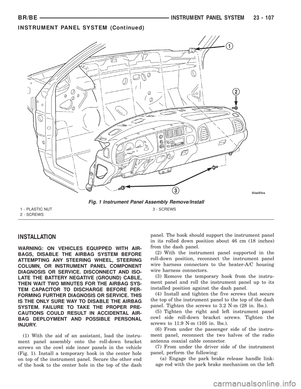
(0.50 inch) (Fig. 1).
(12) Remove the five screws that secure the top of
the instrument panel to the top of the dash panel,
removing the center screw last.
(13) Roll down the instrument panel and install a
temporary hook in the center hole on top of the
instrument panel. Secure the other end of the hook
to the center hole in the top of the dash panel. The
hook should support the instrument panel in its
rolled down position about 46 cm (18 inches) from
the dash panel.
(14) With the instrument panel supported in the
roll-down position, disconnect the instrument panel
wire harness connectors from the heater-A/C housing
wire harness connectors.
(15) With the aid of an assistant, remove the tem-
porary hook and lift the instrument panel assembly
off of the roll-down bracket screws and remove it
from the vehicle.
23 - 106 INSTRUMENT PANEL SYSTEMBR/BE
INSTRUMENT PANEL SYSTEM (Continued)
Page 2680 of 2889
INSTALLATION
WARNING: ON VEHICLES EQUIPPED WITH AIR-
BAGS, DISABLE THE AIRBAG SYSTEM BEFORE
ATTEMPTING ANY STEERING WHEEL, STEERING
COLUMN, OR INSTRUMENT PANEL COMPONENT
DIAGNOSIS OR SERVICE. DISCONNECT AND ISO-
LATE THE BATTERY NEGATIVE (GROUND) CABLE,
THEN WAIT TWO MINUTES FOR THE AIRBAG SYS-
TEM CAPACITOR TO DISCHARGE BEFORE PER-
FORMING FURTHER DIAGNOSIS OR SERVICE. THIS
IS THE ONLY SURE WAY TO DISABLE THE AIRBAG
SYSTEM. FAILURE TO TAKE THE PROPER PRE-
CAUTIONS COULD RESULT IN ACCIDENTAL AIR-
BAG DEPLOYMENT AND POSSIBLE PERSONAL
INJURY.
(1) With the aid of an assistant, load the instru-
ment panel assembly onto the roll-down bracket
screws on the cowl side inner panels in the vehicle
(Fig. 1). Install a temporary hook in the center hole
on top of the instrument panel. Secure the other end
of the hook to the center hole in the top of the dashpanel. The hook should support the instrument panel
in its rolled down position about 46 cm (18 inches)
from the dash panel.
(2) With the instrument panel supported in the
roll-down position, reconnect the instrument panel
wire harness connectors to the heater-A/C housing
wire harness connectors.
(3) Remove the temporary hook from the instru-
ment panel and roll the instrument panel up to its
installed position against the dash panel.
(4) Install and tighten the five screws that secure
the top of the instrument panel to the top of the dash
panel. Tighten the screws to 3.2 N´m (28 in. lbs.).
(5) Tighten the right and left instrument panel
cowl side roll-down bracket screws. Tighten the
screws to 11.9 N´m (105 in. lbs.).
(6) From under the passenger side of the instru-
ment panel, reconnect the two halves of the radio
antenna coaxial cable connector.
(7) From under the driver side of the instrument
panel, perform the following:
(a) Engage the park brake release handle link-
age rod with the park brake mechanism on the left
Fig. 1 Instrument Panel Assembly Remove/Install
1 - PLASTIC NUT
2 - SCREWS3 - SCREWS
BR/BEINSTRUMENT PANEL SYSTEM 23 - 107
INSTRUMENT PANEL SYSTEM (Continued)