2001 DODGE RAM ESP
[x] Cancel search: ESPPage 710 of 2889
(5) Before starting engine, operate accelerator
pedal to check for any binding.
(6) Install cable/lever cover.
SPEED CONTROL SERVO
DESCRIPTION
A speed control servo is not used if equipped
with both a diesel engine and a manual trans-
mission.
The servo unit consists of a solenoid valve body,
and a vacuum chamber. The solenoid valve body con-
tains three solenoids:
²Vacuum
²Vent
²Dump
The vacuum chamber contains a diaphragm with a
cable attached to control the throttle linkage.
OPERATION
A speed control servo is not used if equipped
with both a diesel engine and a manual trans-
mission.
The Powertrain Control Module (PCM) controls the
solenoid valve body. The solenoid valve body controls
the application and release of vacuum to the dia-
phragm of the vacuum servo. The servo unit cannot
be repaired and is serviced only as a complete assem-
bly.
Power is supplied to the servo's by the PCM
through the brake switch. The PCM controls the
ground path for the vacuum and vent solenoids.
The dump solenoid is energized anytime it receives
power. If power to the dump solenoid is interrupted,
the solenoid dumps vacuum in the servo. This pro-
vides a safety backup to the vent and vacuum sole-
noids.
The vacuum and vent solenoids must be grounded
at the PCM to operate. When the PCM grounds the
vacuum servo solenoid, the solenoid allows vacuum
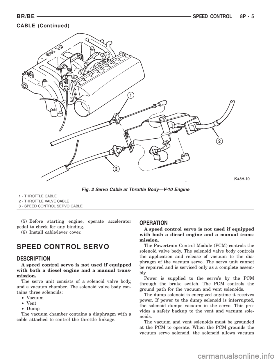
Fig. 2 Servo Cable at Throttle BodyÐV-10 Engine
1 - THROTTLE CABLE
2 - THROTTLE VALVE CABLE
3 - SPEED CONTROL SERVO CABLE
BR/BESPEED CONTROL 8P - 5
CABLE (Continued)
Page 712 of 2889
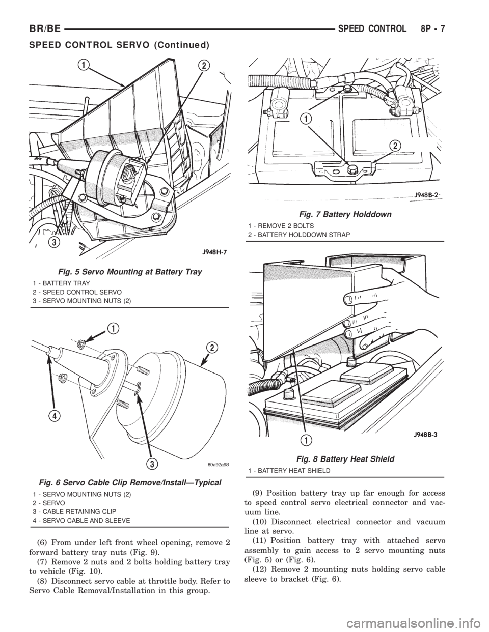
(6) From under left front wheel opening, remove 2
forward battery tray nuts (Fig. 9).
(7) Remove 2 nuts and 2 bolts holding battery tray
to vehicle (Fig. 10).
(8) Disconnect servo cable at throttle body. Refer to
Servo Cable Removal/Installation in this group.(9) Position battery tray up far enough for access
to speed control servo electrical connector and vac-
uum line.
(10) Disconnect electrical connector and vacuum
line at servo.
(11) Position battery tray with attached servo
assembly to gain access to 2 servo mounting nuts
(Fig. 5) or (Fig. 6).
(12) Remove 2 mounting nuts holding servo cable
sleeve to bracket (Fig. 6).
Fig. 5 Servo Mounting at Battery Tray
1 - BATTERY TRAY
2 - SPEED CONTROL SERVO
3 - SERVO MOUNTING NUTS (2)
Fig. 6 Servo Cable Clip Remove/InstallÐTypical
1 - SERVO MOUNTING NUTS (2)
2 - SERVO
3 - CABLE RETAINING CLIP
4 - SERVO CABLE AND SLEEVE
Fig. 7 Battery Holddown
1 - REMOVE 2 BOLTS
2 - BATTERY HOLDDOWN STRAP
Fig. 8 Battery Heat Shield
1 - BATTERY HEAT SHIELD
BR/BESPEED CONTROL 8P - 7
SPEED CONTROL SERVO (Continued)
Page 714 of 2889
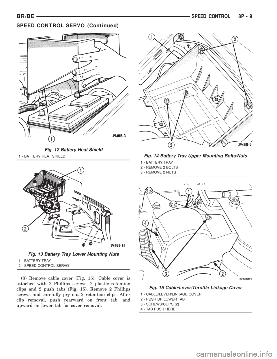
(8) Remove cable cover (Fig. 15). Cable cover is
attached with 2 Phillips screws, 2 plastic retention
clips and 2 push tabs (Fig. 15). Remove 2 Phillips
screws and carefully pry out 2 retention clips. After
clip removal, push rearward on front tab, and
upward on lower tab for cover removal.
Fig. 12 Battery Heat Shield
1 - BATTERY HEAT SHIELD
Fig. 13 Battery Tray Lower Mounting Nuts
1 - BATTERY TRAY
2 - SPEED CONTROL SERVO
Fig. 14 Battery Tray Upper Mounting Bolts/Nuts
1 - BATTERY TRAY
2 - REMOVE 2 BOLTS
3 - REMOVE 2 NUTS
Fig. 15 Cable/Lever/Throttle Linkage Cover
1 - CABLE/LEVER/LINKAGE COVER
2 - PUSH UP LOWER TAB
3 - SCREWS/CLIPS (2)
4 - TAB PUSH HERE
BR/BESPEED CONTROL 8P - 9
SPEED CONTROL SERVO (Continued)
Page 716 of 2889
8.0L V-10 ENGINE
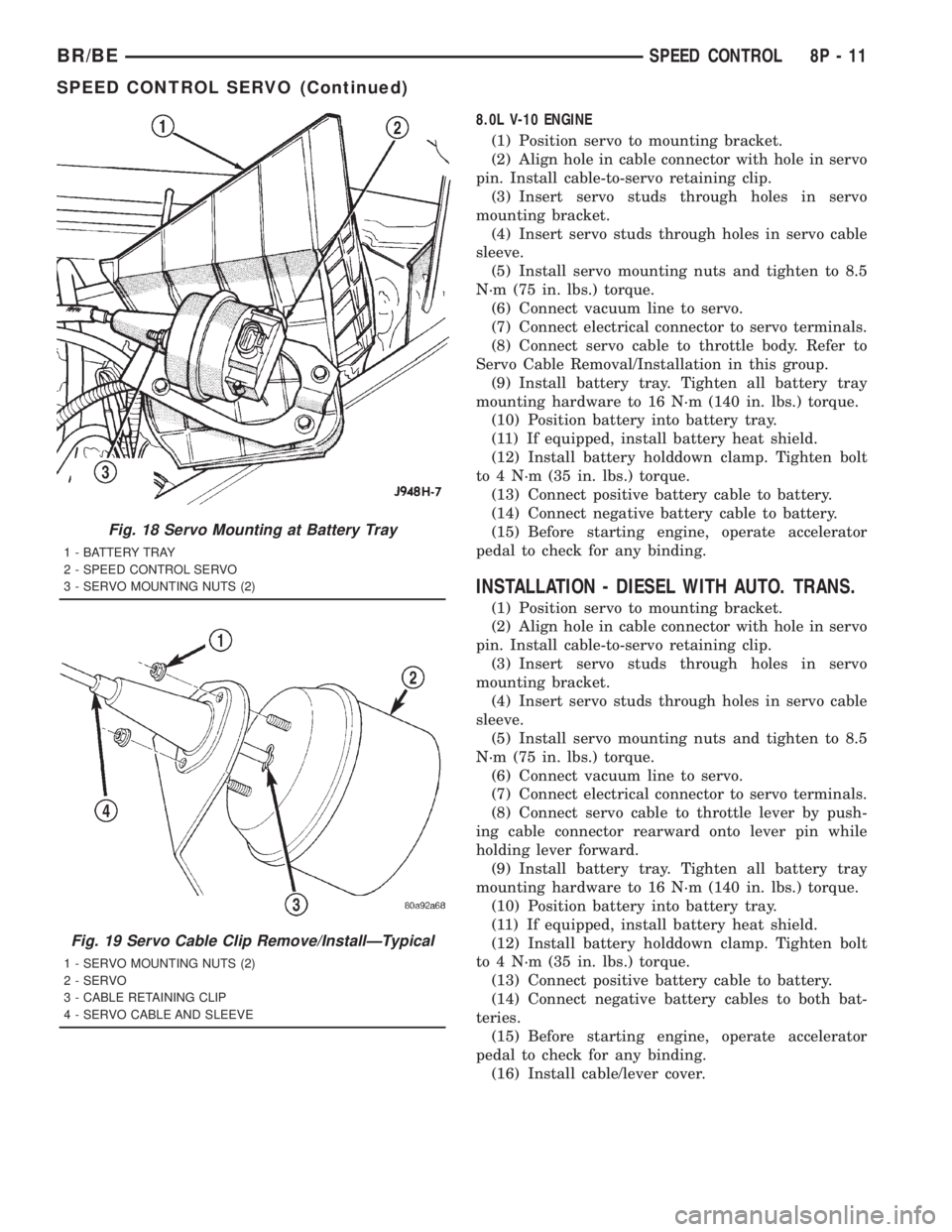
(1) Position servo to mounting bracket.
(2) Align hole in cable connector with hole in servo
pin. Install cable-to-servo retaining clip.
(3) Insert servo studs through holes in servo
mounting bracket.
(4) Insert servo studs through holes in servo cable
sleeve.
(5) Install servo mounting nuts and tighten to 8.5
N´m (75 in. lbs.) torque.
(6) Connect vacuum line to servo.
(7) Connect electrical connector to servo terminals.
(8) Connect servo cable to throttle body. Refer to
Servo Cable Removal/Installation in this group.
(9) Install battery tray. Tighten all battery tray
mounting hardware to 16 N´m (140 in. lbs.) torque.
(10) Position battery into battery tray.
(11) If equipped, install battery heat shield.
(12) Install battery holddown clamp. Tighten bolt
to 4 N´m (35 in. lbs.) torque.
(13) Connect positive battery cable to battery.
(14) Connect negative battery cable to battery.
(15) Before starting engine, operate accelerator
pedal to check for any binding.
INSTALLATION - DIESEL WITH AUTO. TRANS.
(1) Position servo to mounting bracket.
(2) Align hole in cable connector with hole in servo
pin. Install cable-to-servo retaining clip.
(3) Insert servo studs through holes in servo
mounting bracket.
(4) Insert servo studs through holes in servo cable
sleeve.
(5) Install servo mounting nuts and tighten to 8.5
N´m (75 in. lbs.) torque.
(6) Connect vacuum line to servo.
(7) Connect electrical connector to servo terminals.
(8) Connect servo cable to throttle lever by push-
ing cable connector rearward onto lever pin while
holding lever forward.
(9) Install battery tray. Tighten all battery tray
mounting hardware to 16 N´m (140 in. lbs.) torque.
(10) Position battery into battery tray.
(11) If equipped, install battery heat shield.
(12) Install battery holddown clamp. Tighten bolt
to 4 N´m (35 in. lbs.) torque.
(13) Connect positive battery cable to battery.
(14) Connect negative battery cables to both bat-
teries.
(15) Before starting engine, operate accelerator
pedal to check for any binding.
(16) Install cable/lever cover.
Fig. 18 Servo Mounting at Battery Tray
1 - BATTERY TRAY
2 - SPEED CONTROL SERVO
3 - SERVO MOUNTING NUTS (2)
Fig. 19 Servo Cable Clip Remove/InstallÐTypical
1 - SERVO MOUNTING NUTS (2)
2 - SERVO
3 - CABLE RETAINING CLIP
4 - SERVO CABLE AND SLEEVE
BR/BESPEED CONTROL 8P - 11
SPEED CONTROL SERVO (Continued)
Page 718 of 2889
²If the actual speed is not within 20 mph of the
set speedThe previous disengagement conditions are
programmed for added safety.
Once the speed control has been disengaged,
depressing the ACCEL switch restores the vehicle to
the target speed that was stored in the ECM's RAM.
NOTE: Depressing the OFF switch will erase the set
speed stored in the ECM's RAM.
If, while the speed control is engaged, the driver
wishes to increase vehicle speed, the ECM is pro-
grammed for an acceleration feature. With the
ACCEL switch held closed, the vehicle accelerates
slowly to the desired speed. The new target speed is
stored in the ECM's RAM when the ACCEL switch is
released. The ECM also has a9tap-up9feature in
which vehicle speed increases at a rate of approxi-
mately 2 mph for each momentary switch activation
of the ACCEL switch.
The ECM also provides a means to decelerate with-
out disengaging speed control. To decelerate from an
existing recorded target speed, depress and hold the
COAST switch until the desired speed is reached.
Then release the switch. The ON, OFF switch oper-
ates two components: the ECM's ON, OFF input, and
the battery voltage to the brake switch, which powers
the speed control servo.
REMOVAL
WARNING: BEFORE BEGINNING ANY AIRBAG SYS-
TEM COMPONENT REMOVAL OR INSTALLATION,
REMOVE AND ISOLATE THE NEGATIVE (-)
CABLE(S) FROM THE BATTERY. THIS IS THE ONLY
SURE WAY TO DISABLE THE AIRBAG SYSTEM.
THEN WAIT TWO MINUTES FOR SYSTEM CAPACI-
TOR TO DISCHARGE BEFORE FURTHER SYSTEM
SERVICE. FAILURE TO DO THIS COULD RESULT IN
ACCIDENTAL AIRBAG DEPLOYMENT AND POSSI-
BLE INJURY.
(1) Disconnect and isolate negative battery
cable(s).
(2) Remove airbag module. Refer to 8, Restraint
Systems for procedures.
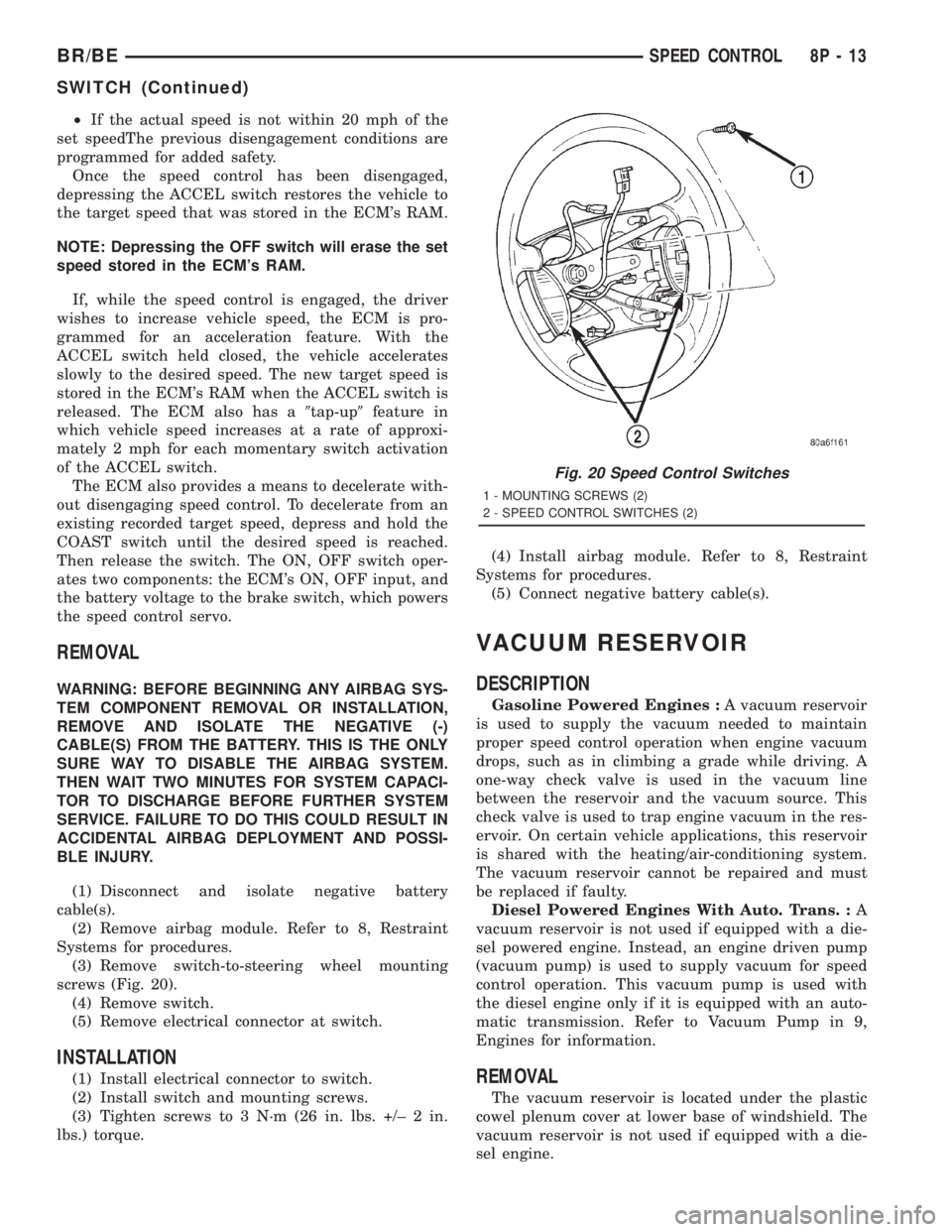
(3) Remove switch-to-steering wheel mounting
screws (Fig. 20).
(4) Remove switch.
(5) Remove electrical connector at switch.
INSTALLATION
(1) Install electrical connector to switch.
(2) Install switch and mounting screws.
(3) Tighten screws to 3 N´m (26 in. lbs. +/± 2 in.
lbs.) torque.(4) Install airbag module. Refer to 8, Restraint
Systems for procedures.
(5) Connect negative battery cable(s).
VACUUM RESERVOIR
DESCRIPTION
Gasoline Powered Engines :A vacuum reservoir
is used to supply the vacuum needed to maintain
proper speed control operation when engine vacuum
drops, such as in climbing a grade while driving. A
one-way check valve is used in the vacuum line
between the reservoir and the vacuum source. This
check valve is used to trap engine vacuum in the res-
ervoir. On certain vehicle applications, this reservoir
is shared with the heating/air-conditioning system.
The vacuum reservoir cannot be repaired and must
be replaced if faulty.
Diesel Powered Engines With Auto. Trans. :A
vacuum reservoir is not used if equipped with a die-
sel powered engine. Instead, an engine driven pump
(vacuum pump) is used to supply vacuum for speed
control operation. This vacuum pump is used with
the diesel engine only if it is equipped with an auto-
matic transmission. Refer to Vacuum Pump in 9,
Engines for information.
REMOVAL
The vacuum reservoir is located under the plastic
cowel plenum cover at lower base of windshield. The
vacuum reservoir is not used if equipped with a die-
sel engine.
Fig. 20 Speed Control Switches
1 - MOUNTING SCREWS (2)
2 - SPEED CONTROL SWITCHES (2)
BR/BESPEED CONTROL 8P - 13
SWITCH (Continued)
Page 720 of 2889
VEHICLE THEFT SECURITY
TABLE OF CONTENTS
page page
VEHICLE THEFT SECURITY
DESCRIPTION............................1
OPERATION.............................2
DIAGNOSIS AND TESTING..................3
VEHICLE THEFT SECURITY SYSTEM........3VTSS INDICATOR
DESCRIPTION............................3
OPERATION.............................3
DIAGNOSIS AND TESTING..................3
VTSS INDICATOR.......................3
VEHICLE THEFT SECURITY
DESCRIPTION
The Vehicle Theft Security System (VTSS) is an
available factory-installed option on this model when
it is also equipped with the high-line or premium
Central Timer Module (CTM). The VTSS is designed
to provide perimeter protection against unauthorized
use or tampering by monitoring the vehicle doors and
the ignition system. If unauthorized vehicle use or
tampering is detected, the system responds by puls-
ing the horn, flashing the headlamps, and preventing
the engine from operating.
The VTSS includes the following major compo-
nents, which are described in further detail else-
where in this service manual:
²Central Timer Module- The high-line or pre-
mium Central Timer Module (CTM) is located under
the driver side end of the instrument panel, inboard
of the instrument panel steering column opening.
The high-line or premium CTM contains a micropro-
cessor and software that allow it to provide many
electronic functions and features not available with
base version of the CTM, including the VTSS. The
CTM provides all of the proper VTSS features and
outputs based upon the monitored inputs. The CTM
circuitry monitors hard wired switch inputs, as well
as message inputs received from other vehicle elec-
tronic modules over the Chrysler Collision Detection
(CCD) data bus network. (Refer to 8 - ELECTRICAL/
ELECTRONIC CONTROL MODULES/BODY CON-
TROL/CENTRAL TIMER MODULE -
DESCRIPTION).
²Door Ajar Switch- A door ajar switch is
located on the hinge pillar of each front door in the
vehicle. These switches provide an input to the VTSS
indicating whether the door is opened or closed.
(Refer to 8 - ELECTRICAL/LAMPS/LIGHTING -
INTERIOR/DOOR AJAR SWITCH - DESCRIPTION).
²Door Cylinder Lock Switch- A door cylinder
lock switch is located on the back of each front door
lock cylinder. This switch provides an input to theVTSS indicating whether the system should remain
armed or be disarmed. (Refer to 8 - ELECTRICAL/
POWER LOCKS/DOOR CYLINDER LOCK SWITCH
- DESCRIPTION).
²Horn Relay- The horn relay is located in the
Power Distribution Center (PDC) in the engine com-
partment near the battery. The horn relay is nor-
mally activated by the horn switch to control the
sounding of the vehicle horn or horns. However, it
can also be activated by an output of the Central
Timer Module (CTM) to provide an audible indication
that unauthorized vehicle use or tampering has been
detected. (Refer to 8 - ELECTRICAL/HORN/HORN
RELAY - DESCRIPTION).
²Headlamp Relay- The headlamp relay (also
known as the security relay) is located in the Power
Distribution Center (PDC) in the engine compart-
ment near the battery. The headlamp relay is nor-
mally activated by the Central Timer Module (CTM)
based upon inputs from the Remote Keyless Entry
(RKE) panic mode feature. However, it can also be
activated by an output of the CTM to flash the head-
lamp low beams to provide a highly visible indication
that unauthorized vehicle use or tampering has been
detected. (Refer to 8 - ELECTRICAL/LAMPS/LIGHT-
ING - EXTERIOR/HEADLAMP RELAY - DESCRIP-
TION).
²VTSS Indicator- A red Light Emitting Diode
(LED) located on the lower surface of the overhead
console near the windshield is illuminated by an out-
put of the Central Timer Module (CTM) to indicate
the status of the VTSS. This LED is integral to the
electronic circuit board for the Compass Mini-Trip
Computer (CMTC). (Refer to 8 - ELECTRICAL/
OVERHEAD CONSOLE/COMPASS/MINI-TRIP
COMPUTER - DESCRIPTION).
The engine no-run feature of the VTSS relies upon
communication between the high-line or premium
CTM and the Powertrain Control Module (PCM) over
the Chrysler Collision Detection (CCD) data bus net-
work.
Hard wired circuitry connects many of the VTSS
components to each other through the electrical sys-
BR/BEVEHICLE THEFT SECURITY 8Q - 1
Page 722 of 2889
er-up mode will also apply if the battery goes dead
while the system is armed, and battery jump-starting
is attempted. The engine no-run feature will prevent
the engine from starting until the alarm system has
been actively or passively disarmed. The VTSS will
be armed until the technician or vehicle operator has
actively or passively disarmed the alarm system. If
the VTSS is in the disarmed mode prior to a battery
disconnect or failure, it will remain disarmed after
the battery is reconnected or replaced, or if jump-
starting is attempted.
TAMPER ALERT
The VTSS tamper alert feature will sound the horn
three times upon disarming, if the alarm was trig-
gered and has since timed-out (about fifteen min-
utes). This feature alerts the vehicle operator that
the VTSS alarm was activated while the vehicle was
unattended.
DIAGNOSIS AND TESTING - VEHICLE THEFT
SECURITY SYSTEM
The VTSS-related hard wired inputs to and out-
puts from the high-line or premium Central Timer
Module (CTM) may be diagnosed and tested using
conventional diagnostic tools and procedures. Refer
to the appropriate wiring information. The wiring
information includes wiring diagrams, proper wire
and connector repair procedures, further details on
wire harness routing and retention, as well as pin-
out and location views for the various wire harness
connectors, splices and grounds.
However, conventional diagnostic methods may not
prove conclusive in the diagnosis of the CTM, the
Powertrain Control Module (PCM), or the Chrysler
Collision Detection (CCD) data bus network. In order
to obtain conclusive testing of the VTSS, the CTM,
the PCM, and the CCD data bus network must also
be checked. The most reliable, efficient, and accurate
means to diagnose the VTSS requires the use of a
DRBIIIž scan tool. Refer to the appropriate diagnos-
tic information. The DRBIIIž scan tool can provide
confirmation that the CCD data bus network is func-
tional, that all of the electronic modules are sending
and receiving the proper messages over the CCD
data bus, and that these modules are receiving the
proper hard wired inputs and responding with the
proper hard wired outputs needed to perform their
functions. See the ªVehicle Theft Security Systemº
menu item on the DRBIIIž scan tool.
WARNING: ON VEHICLES EQUIPPED WITH AIR-
BAGS, DISABLE THE AIRBAG SYSTEM BEFORE
ATTEMPTING ANY STEERING WHEEL, STEERING
COLUMN, OR INSTRUMENT PANEL COMPONENT
DIAGNOSIS OR SERVICE. DISCONNECT AND ISO-LATE THE BATTERY NEGATIVE (GROUND) CABLE,
THEN WAIT TWO MINUTES FOR THE AIRBAG SYS-
TEM CAPACITOR TO DISCHARGE BEFORE PER-
FORMING FURTHER DIAGNOSIS OR SERVICE. THIS
IS THE ONLY SURE WAY TO DISABLE THE AIRBAG
SYSTEM. FAILURE TO TAKE THE PROPER PRE-
CAUTIONS COULD RESULT IN ACCIDENTAL AIR-
BAG DEPLOYMENT AND POSSIBLE PERSONAL
INJURY.
VTSS INDICATOR
DESCRIPTION
The Vehicle Theft Security System (VTSS) indica-
tor consists of a red Light-Emitting Diode (LED)
located on the electronic circuit board of the Compass
Mini-Trip Computer (CMTC) within the overhead
console. The LED extends through a hole in the
CMTC lens located near the forward end of the over-
head console housing near the windshield.
The VTSS indicator cannot be adjusted or repaired
and, if faulty or damaged, the entire CMTC unit
must be replaced. (Refer to 8 - ELECTRICAL/OVER-
HEAD CONSOLE/COMPASS/MINI-TRIP COM-
PUTER - DESCRIPTION).
OPERATION
The Vehicle Theft Security System (VTSS) indica-
tor gives a visible indication of the VTSS arming sta-
tus. One side of Light-Emitting Diode (LED) in the
VTSS indicator is connected to battery current
through a fused B(+) circuit and a fuse in the Junc-
tion Block (JB), so the indicator remains functional
regardless of the ignition switch position. The other
side of the LED is hard wired to the Central Timer
Module (CTM), which controls the operation of the
VTSS indicator by pulling this side of the LED cir-
cuit to ground. When the VTSS arming is in
progress, the CTM will flash the LED rapidly on and
off for about fifteen seconds. When the VTSS has
been successfully armed, the CTM will flash the LED
on and off continually at a much slower rate until
the VTSS has been disarmed. The VTSS indicator
can be diagnosed using conventional diagnostic tools
and methods.
DIAGNOSIS AND TESTING - VTSS INDICATOR
The diagnosis found here addresses an inoperative
Vehicle Theft Security System (VTSS) indicator con-
dition. If the problem being diagnosed is related to
indicator accuracy, be certain to confirm that the
problem is with the indicator and not with an inop-
erative VTSS. (Refer to 8 - ELECTRICAL/VEHICLE
THEFT SECURITY SYSTEM- DIAGNOSIS AND
BR/BEVEHICLE THEFT SECURITY 8Q - 3
VEHICLE THEFT SECURITY (Continued)
Page 726 of 2889
activates the washer pump/motor, which dispenses
washer fluid onto the windshield glass through the
washer nozzles.
When the ignition switch is in the Accessory or On
positions, battery current from a fuse in the Junction
Block (JB) is provided through a fused ignition
switch output (run-acc) circuit to the wiper motor
park switch, the wiper relay, and the multi-function
switch. The internal circuitry of the multi-function
switch provides a direct hard wired battery current
output to the low speed or high speed brushes of the
wiper motor when the Lo or Hi switch setting is
selected, which causes the wipers to cycle at the
selected speed. The intermittent wipe, and wipe-af-
ter-wash features of the wiper and washer system
are provided by the electronic intermittent wipe logic
circuit within the Central Timer Module (CTM). In
order to provide the intermittent wipe feature, the
CTM monitors the wiper switch state and the wiper
motor park switch state. In order to provide the
wipe-after-wash feature, the CTM monitors both the
washer switch state and the wiper motor park switch
state. When a Delay position is selected with the
multi-function switch control knob, the CTM logic cir-
cuit responds by calculating the correct delay inter-
val. The CTM then energizes the wiper relay by
pulling the relay control coil to ground. The ener-
gized wiper relay directs battery current through the
normally open contact of the relay back through the
internal circuitry of the multi-function switch to the
low speed brush of the wiper motor. The CTM moni-
tors the wiper motor operation through the wiper
park switch sense circuit, which allows the CTM to
determine the proper timing to begin the next wiper
blade sweep. The normal delay intervals are driver
adjustable from about one-half second to about eigh-
teen seconds.
The high-line and premium CTM also provides a
speed sensitive intermittent wipe feature. By moni-
toring vehicle speed messages received from the Pow-
ertrain Control Module (PCM) over the Chrysler
Collision Detection (CCD) data bus network, the
high-line or premium CTM is able to adjust the delay
intervals to compensate for vehicle speed. Above
about sixteen kilometers-per-hour (ten miles-per-
hour) the delay is driver adjustable from about one-
half second to about eighteen seconds. Below about
sixteen kilometers-per-hour (ten miles-per-hour) the
delay times are doubled by the CTM, from about one
second to about thirty-six seconds.
When the Off position of the multi-function switch
wiper control knob is selected, one of two events is
possible. The event that will occur depends upon the
position of the wiper blades on the windshield at the
moment that the Off position is selected. If the wiper
blades are in the down position on the windshieldwhen the Off position is selected, the park switch
that is integral to the wiper motor is closed to ground
and the wiper motor ceases to operate. If the wiper
blades are not in the down position on the windshield
at the moment the Off position is selected, the park
switch is closed to battery current through a fused
ignition switch output (run-acc) circuit. The park
switch sense circuit directs this battery current to
the low speed brush of the wiper motor through the
normally closed contact of the wiper relay and the
internal Off position circuitry of the multi-function
switch. This causes the wiper motor to continue run-
ning until the wiper blades are in the down position
on the windshield and the park switch is again
closed to ground.
When the Wash position of the multi-function
switch is selected, the Wash position circuitry within
the switch directs battery current to the washer
pump/motor. The CTM monitors the washer switch
state through a washer switch sense input. When the
washer switch is closed with the wiper system turned
Off, the CTM operates the wiper motor through the
wiper relay in the same manner as it does to provide
the Delay mode operation. After the state of the
washer switch changes to open, the CTM monitors
the wiper motor through the wiper park switch sense
circuit, which allows the CTM to monitor the number
of wiper blade sweeps.
Proper testing of the CTM, the PCM, or the CCD
data bus vehicle speed messages requires a DRBIIIt
scan tool. Refer to the appropriate diagnostic infor-
mation. Refer to the owner's manual in the vehicle
glove box for more information on the features and
operation of the wiper and washer system.
DIAGNOSIS AND TESTING - WIPER &
WASHER SYSTEM
WIPER SYSTEM
The diagnosis found here addresses an electrically
inoperative wiper system. If the wiper motor oper-
ates, but the wipers do not move on the windshield,
replace the faulty wiper module. If the wipers oper-
ate, but chatter, lift, or do not clear the glass, clean
and inspect the wiper system components as
required. (Refer to 8 - ELECTRICAL/WIPERS/
WASHERS - INSPECTION) and (Refer to 8 - ELEC-
TRICAL/WIPERS/WASHERS - CLEANING). Refer to
the appropriate wiring information. The wiring infor-
mation includes wiring diagrams, proper wire and
connector repair procedures, details of wire harness
routing and retention, connector pin-out information
and location views for the various wire harness con-
nectors, splices and grounds.
The following tests will help to diagnose the hard
wired components and circuits of the wiper system.
BR/BEWIPERS/WASHERS 8R - 3
WIPERS/WASHERS (Continued)