2001 DODGE RAM service
[x] Cancel search: servicePage 2783 of 2889
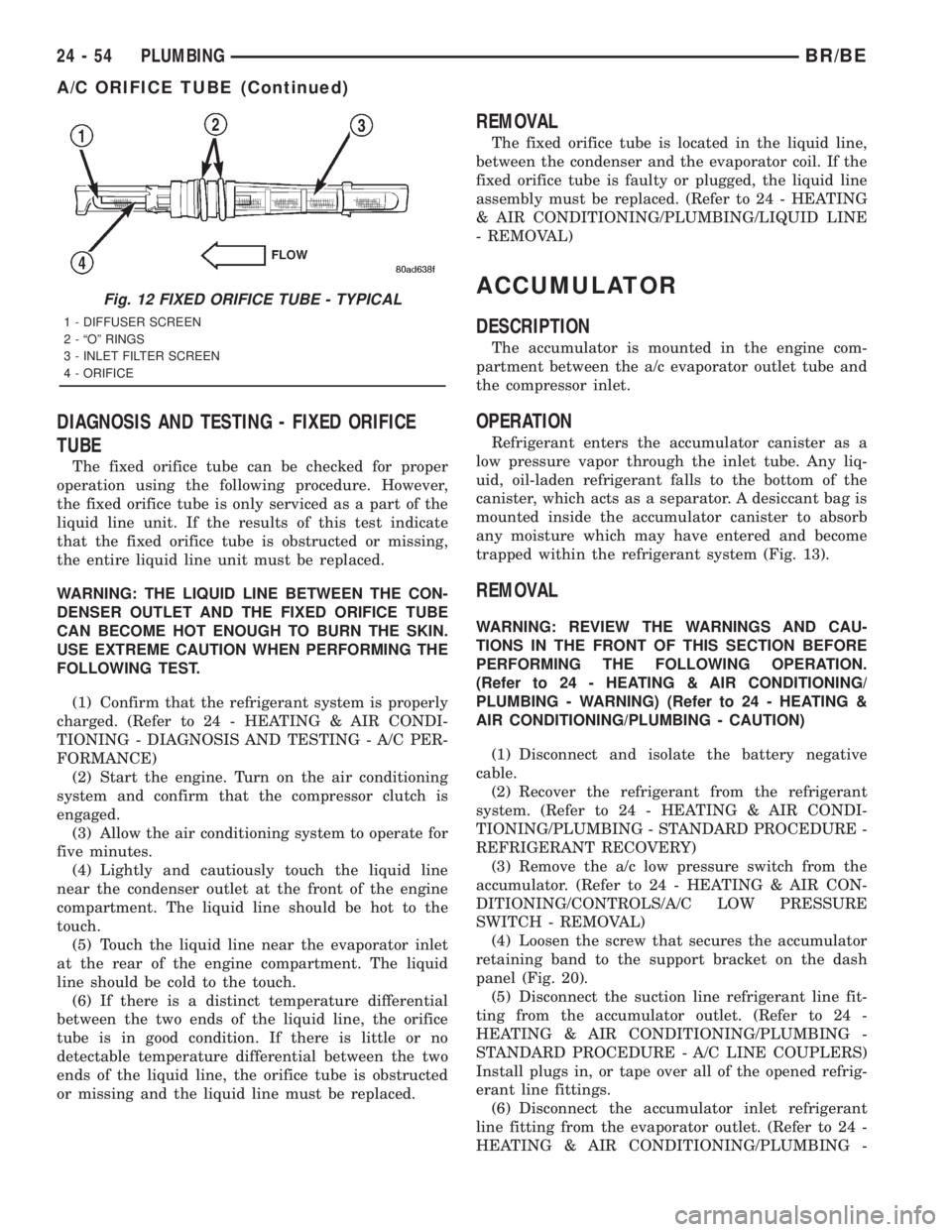
DIAGNOSIS AND TESTING - FIXED ORIFICE
TUBE
The fixed orifice tube can be checked for proper
operation using the following procedure. However,
the fixed orifice tube is only serviced as a part of the
liquid line unit. If the results of this test indicate
that the fixed orifice tube is obstructed or missing,
the entire liquid line unit must be replaced.
WARNING: THE LIQUID LINE BETWEEN THE CON-
DENSER OUTLET AND THE FIXED ORIFICE TUBE
CAN BECOME HOT ENOUGH TO BURN THE SKIN.
USE EXTREME CAUTION WHEN PERFORMING THE
FOLLOWING TEST.
(1) Confirm that the refrigerant system is properly
charged. (Refer to 24 - HEATING & AIR CONDI-
TIONING - DIAGNOSIS AND TESTING - A/C PER-
FORMANCE)
(2) Start the engine. Turn on the air conditioning
system and confirm that the compressor clutch is
engaged.
(3) Allow the air conditioning system to operate for
five minutes.
(4) Lightly and cautiously touch the liquid line
near the condenser outlet at the front of the engine
compartment. The liquid line should be hot to the
touch.
(5) Touch the liquid line near the evaporator inlet
at the rear of the engine compartment. The liquid
line should be cold to the touch.
(6) If there is a distinct temperature differential
between the two ends of the liquid line, the orifice
tube is in good condition. If there is little or no
detectable temperature differential between the two
ends of the liquid line, the orifice tube is obstructed
or missing and the liquid line must be replaced.
REMOVAL
The fixed orifice tube is located in the liquid line,
between the condenser and the evaporator coil. If the
fixed orifice tube is faulty or plugged, the liquid line
assembly must be replaced. (Refer to 24 - HEATING
& AIR CONDITIONING/PLUMBING/LIQUID LINE
- REMOVAL)
ACCUMULATOR
DESCRIPTION
The accumulator is mounted in the engine com-
partment between the a/c evaporator outlet tube and
the compressor inlet.
OPERATION
Refrigerant enters the accumulator canister as a
low pressure vapor through the inlet tube. Any liq-
uid, oil-laden refrigerant falls to the bottom of the
canister, which acts as a separator. A desiccant bag is
mounted inside the accumulator canister to absorb
any moisture which may have entered and become
trapped within the refrigerant system (Fig. 13).
REMOVAL
WARNING: REVIEW THE WARNINGS AND CAU-
TIONS IN THE FRONT OF THIS SECTION BEFORE
PERFORMING THE FOLLOWING OPERATION.
(Refer to 24 - HEATING & AIR CONDITIONING/
PLUMBING - WARNING) (Refer to 24 - HEATING &
AIR CONDITIONING/PLUMBING - CAUTION)
(1) Disconnect and isolate the battery negative
cable.
(2) Recover the refrigerant from the refrigerant
system. (Refer to 24 - HEATING & AIR CONDI-
TIONING/PLUMBING - STANDARD PROCEDURE -
REFRIGERANT RECOVERY)
(3) Remove the a/c low pressure switch from the
accumulator. (Refer to 24 - HEATING & AIR CON-
DITIONING/CONTROLS/A/C LOW PRESSURE
SWITCH - REMOVAL)
(4) Loosen the screw that secures the accumulator
retaining band to the support bracket on the dash
panel (Fig. 20).
(5) Disconnect the suction line refrigerant line fit-
ting from the accumulator outlet. (Refer to 24 -
HEATING & AIR CONDITIONING/PLUMBING -
STANDARD PROCEDURE - A/C LINE COUPLERS)
Install plugs in, or tape over all of the opened refrig-
erant line fittings.
(6) Disconnect the accumulator inlet refrigerant
line fitting from the evaporator outlet. (Refer to 24 -
HEATING & AIR CONDITIONING/PLUMBING -
Fig. 12 FIXED ORIFICE TUBE - TYPICAL
1 - DIFFUSER SCREEN
2 - ªOº RINGS
3 - INLET FILTER SCREEN
4 - ORIFICE
24 - 54 PLUMBINGBR/BE
A/C ORIFICE TUBE (Continued)
Page 2785 of 2889
more information on the engine cooling system, the
engine coolant and the heater hoses.
REMOVAL
(1) Remove the HVAC housing from the vehicle.
(Refer to 24 - HEATING & AIR CONDITIONING/
DISTRIBUTION/HVAC HOUSING - REMOVAL)
(2) Remove the screws and retainers that secure
the heater core to the HVAC housing.
(3) Lift the heater core straight up and out of the
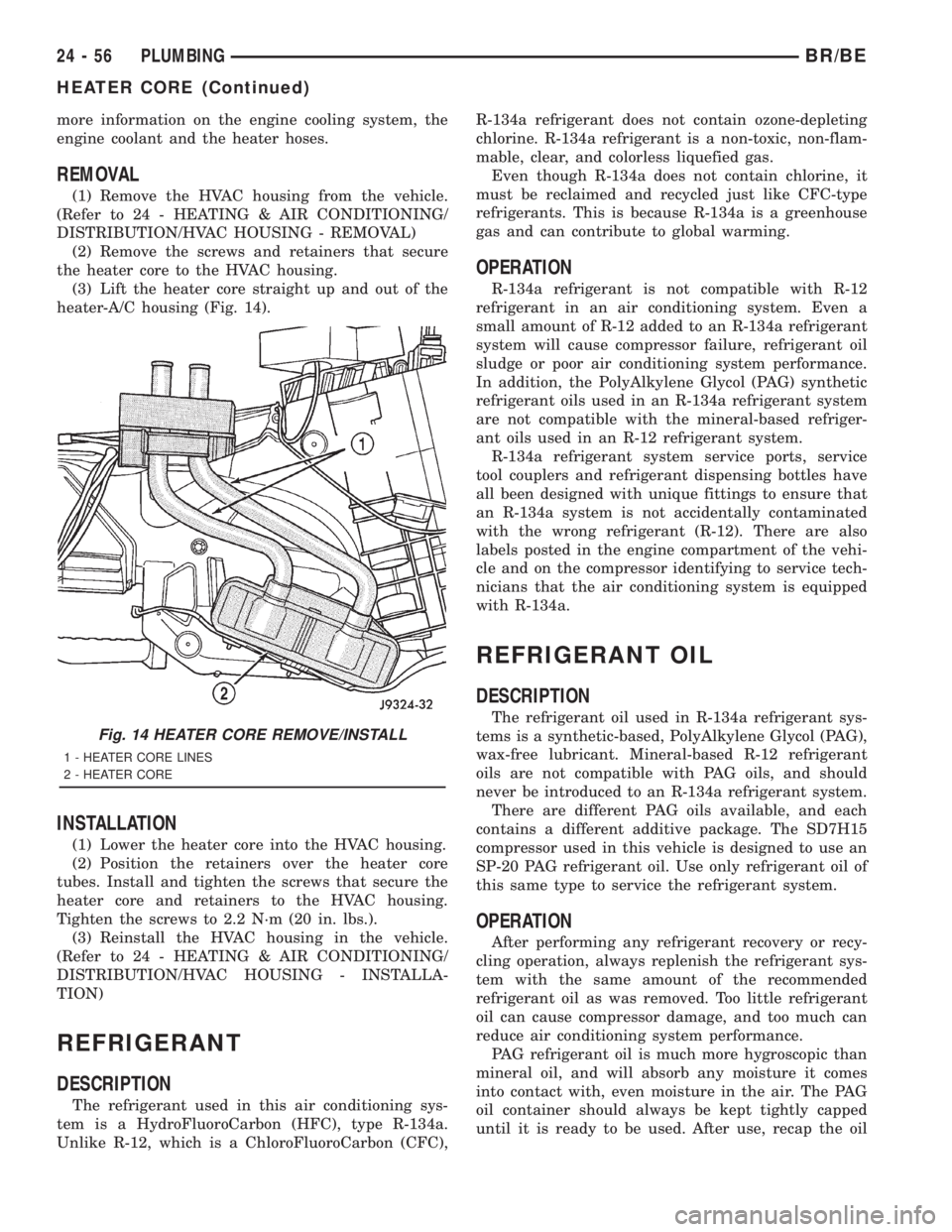
heater-A/C housing (Fig. 14).
INSTALLATION
(1) Lower the heater core into the HVAC housing.
(2) Position the retainers over the heater core
tubes. Install and tighten the screws that secure the
heater core and retainers to the HVAC housing.
Tighten the screws to 2.2 N´m (20 in. lbs.).
(3) Reinstall the HVAC housing in the vehicle.
(Refer to 24 - HEATING & AIR CONDITIONING/
DISTRIBUTION/HVAC HOUSING - INSTALLA-
TION)
REFRIGERANT
DESCRIPTION
The refrigerant used in this air conditioning sys-
tem is a HydroFluoroCarbon (HFC), type R-134a.
Unlike R-12, which is a ChloroFluoroCarbon (CFC),R-134a refrigerant does not contain ozone-depleting
chlorine. R-134a refrigerant is a non-toxic, non-flam-
mable, clear, and colorless liquefied gas.
Even though R-134a does not contain chlorine, it
must be reclaimed and recycled just like CFC-type
refrigerants. This is because R-134a is a greenhouse
gas and can contribute to global warming.
OPERATION
R-134a refrigerant is not compatible with R-12
refrigerant in an air conditioning system. Even a
small amount of R-12 added to an R-134a refrigerant
system will cause compressor failure, refrigerant oil
sludge or poor air conditioning system performance.
In addition, the PolyAlkylene Glycol (PAG) synthetic
refrigerant oils used in an R-134a refrigerant system
are not compatible with the mineral-based refriger-
ant oils used in an R-12 refrigerant system.
R-134a refrigerant system service ports, service
tool couplers and refrigerant dispensing bottles have
all been designed with unique fittings to ensure that
an R-134a system is not accidentally contaminated
with the wrong refrigerant (R-12). There are also
labels posted in the engine compartment of the vehi-
cle and on the compressor identifying to service tech-
nicians that the air conditioning system is equipped
with R-134a.
REFRIGERANT OIL
DESCRIPTION
The refrigerant oil used in R-134a refrigerant sys-
tems is a synthetic-based, PolyAlkylene Glycol (PAG),
wax-free lubricant. Mineral-based R-12 refrigerant
oils are not compatible with PAG oils, and should
never be introduced to an R-134a refrigerant system.
There are different PAG oils available, and each
contains a different additive package. The SD7H15
compressor used in this vehicle is designed to use an
SP-20 PAG refrigerant oil. Use only refrigerant oil of
this same type to service the refrigerant system.
OPERATION
After performing any refrigerant recovery or recy-
cling operation, always replenish the refrigerant sys-
tem with the same amount of the recommended
refrigerant oil as was removed. Too little refrigerant
oil can cause compressor damage, and too much can
reduce air conditioning system performance.
PAG refrigerant oil is much more hygroscopic than
mineral oil, and will absorb any moisture it comes
into contact with, even moisture in the air. The PAG
oil container should always be kept tightly capped
until it is ready to be used. After use, recap the oil
Fig. 14 HEATER CORE REMOVE/INSTALL
1 - HEATER CORE LINES
2 - HEATER CORE
24 - 56 PLUMBINGBR/BE
HEATER CORE (Continued)
Page 2801 of 2889
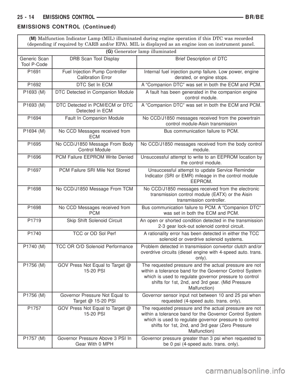
(M)Malfunction Indicator Lamp (MIL) illuminated during engine operation if this DTC was recorded
(depending if required by CARB and/or EPA). MIL is displayed as an engine icon on instrument panel.
(G)Generator lamp illuminated
Generic Scan
Tool P-CodeDRB Scan Tool Display Brief Description of DTC
P1691 Fuel Injection Pump Controller
Calibration ErrorInternal fuel injection pump failure. Low power, engine
derated, or engine stops.
P1692 DTC Set In ECM A9Companion DTC9was set in both the ECM and PCM.
P1693 (M) DTC Detected in Companion Module A fault has been generated in the companion engine
control module.
P1693 (M) DTC Detected in PCM/ECM or DTC
Detected in ECMA9Companion DTC9was set in both the ECM and PCM.
P1694 Fault In Companion Module No CCD/J1850 messages received from the powertrain
control module-Aisin transmission
P1694 (M) No CCD Messages received from
ECMBus communication failure to PCM.
P1695 No CCD/J1850 Message From Body
Control ModuleNo CCD/J1850 messages received from the body control
module.
P1696 PCM Failure EEPROM Write Denied Unsuccessful attempt to write to an EEPROM location by
the control module.
P1697 PCM Failure SRI Mile Not Stored Unsuccessful attempt to update Service Reminder
Indicator (SRI or EMR) mileage in the control module
EEPROM.
P1698 No CCD/J1850 Message From TCM No CCD/J1850 messages received from the electronic
transmission control module (EATX) or the Aisin
transmission controller.
P1698 No CCD Messages received from
PCMBus communication failure to PCM. A9Companion DTC9
was set in both the ECM and PCM.
P1719 Skip Shift Solenoid Circuit An open or shorted condition detected in the transmission
2-3 gear lock-out solenoid control circuit.
P1740 TCC or OD Sol Perf A rationality error has been detected in either the TCC
solenoid or overdrive solenoid systems.
P1740 (M) TCC OR O/D Solenoid Performance Problem detected in transmission convertor clutch and/or
overdrive circuits (diesel engine with 4-speed auto. trans.
only).
P1756 (M) GOV Press Not Equal to Target @
15-20 PSIThe requested pressure and the actual pressure are not
within a tolerance band for the Governor Control System
which is used to regulate governor pressure to control
shifts for 1st, 2nd, and 3rd gear. (Mid Pressure
Malfunction)
P1756 (M) Governor Pressure Not Equal to
Target @ 15-20 PSIGovernor sensor input not between 10 and 25 psi when
requested (4-speed auto. trans. only).
P1757 GOV Press Not Equal to Target @
15-20 PSIThe requested pressure and the actual pressure are not
within a tolerance band for the Governor Control System
which is used to regulate governor pressure to control
shifts for 1st, 2nd, and 3rd gear (Zero Pressure
Malfunction)
P1757 (M) Governor Pressure Above 3 PSI In
Gear With 0 MPHGovernor pressure greater than 3 psi when requested to
be 0 psi (4-speed auto. trans. only).
25 - 14 EMISSIONS CONTROLBR/BE
EMISSIONS CONTROL (Continued)
Page 2816 of 2889
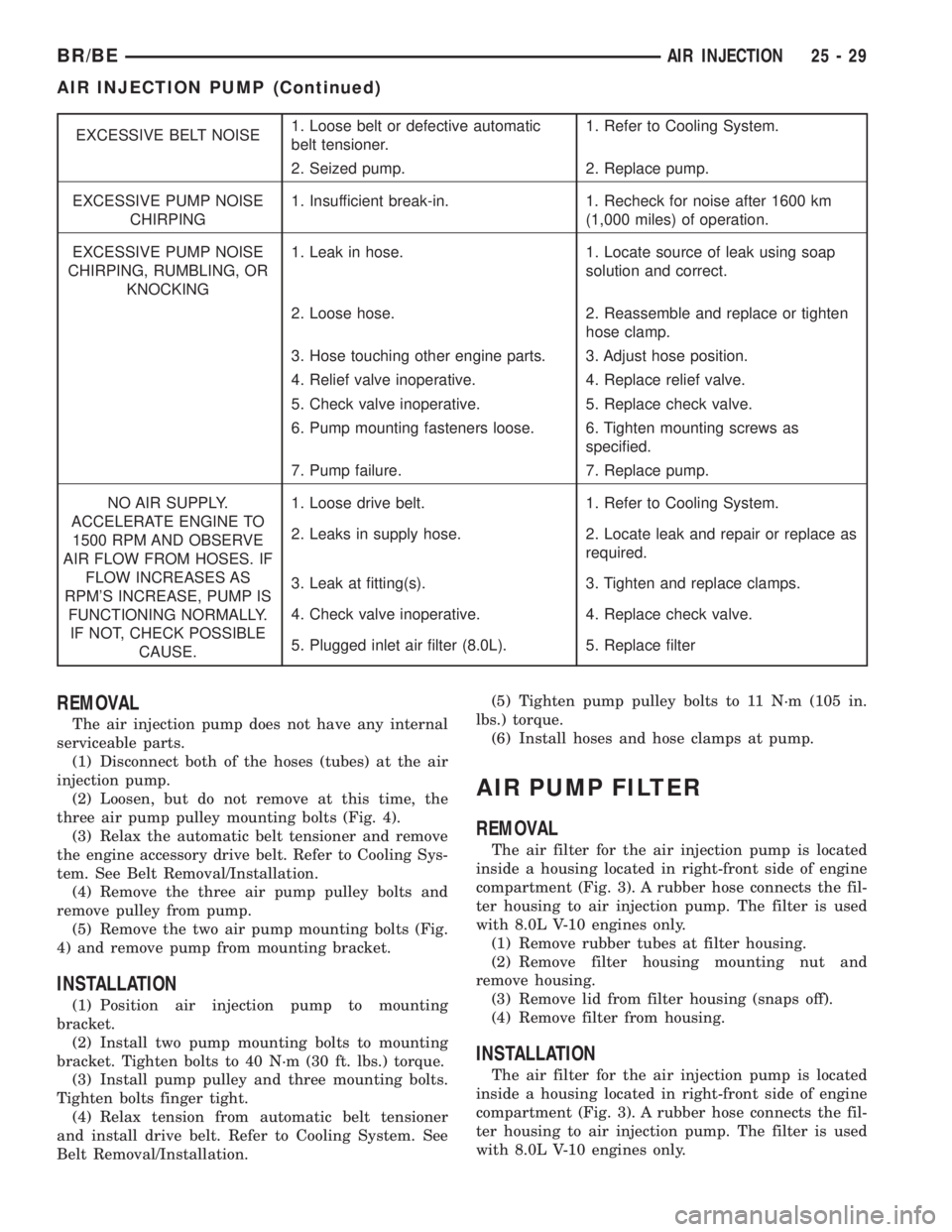
EXCESSIVE BELT NOISE1. Loose belt or defective automatic
belt tensioner.1. Refer to Cooling System.
2. Seized pump. 2. Replace pump.
EXCESSIVE PUMP NOISE
CHIRPING1. Insufficient break-in. 1. Recheck for noise after 1600 km
(1,000 miles) of operation.
EXCESSIVE PUMP NOISE
CHIRPING, RUMBLING, OR
KNOCKING1. Leak in hose. 1. Locate source of leak using soap
solution and correct.
2. Loose hose. 2. Reassemble and replace or tighten
hose clamp.
3. Hose touching other engine parts. 3. Adjust hose position.
4. Relief valve inoperative. 4. Replace relief valve.
5. Check valve inoperative. 5. Replace check valve.
6. Pump mounting fasteners loose. 6. Tighten mounting screws as
specified.
7. Pump failure. 7. Replace pump.
NO AIR SUPPLY.
ACCELERATE ENGINE TO
1500 RPM AND OBSERVE
AIR FLOW FROM HOSES. IF
FLOW INCREASES AS
RPM'S INCREASE, PUMP IS
FUNCTIONING NORMALLY.
IF NOT, CHECK POSSIBLE
CAUSE.1. Loose drive belt. 1. Refer to Cooling System.
2. Leaks in supply hose. 2. Locate leak and repair or replace as
required.
3. Leak at fitting(s). 3. Tighten and replace clamps.
4. Check valve inoperative. 4. Replace check valve.
5. Plugged inlet air filter (8.0L). 5. Replace filter
REMOVAL
The air injection pump does not have any internal
serviceable parts.
(1) Disconnect both of the hoses (tubes) at the air
injection pump.
(2) Loosen, but do not remove at this time, the
three air pump pulley mounting bolts (Fig. 4).
(3) Relax the automatic belt tensioner and remove
the engine accessory drive belt. Refer to Cooling Sys-
tem. See Belt Removal/Installation.
(4) Remove the three air pump pulley bolts and
remove pulley from pump.
(5) Remove the two air pump mounting bolts (Fig.
4) and remove pump from mounting bracket.
INSTALLATION
(1) Position air injection pump to mounting
bracket.
(2) Install two pump mounting bolts to mounting
bracket. Tighten bolts to 40 N´m (30 ft. lbs.) torque.
(3) Install pump pulley and three mounting bolts.
Tighten bolts finger tight.
(4) Relax tension from automatic belt tensioner
and install drive belt. Refer to Cooling System. See
Belt Removal/Installation.(5) Tighten pump pulley bolts to 11 N´m (105 in.
lbs.) torque.
(6) Install hoses and hose clamps at pump.
AIR PUMP FILTER
REMOVAL
The air filter for the air injection pump is located
inside a housing located in right-front side of engine
compartment (Fig. 3). A rubber hose connects the fil-
ter housing to air injection pump. The filter is used
with 8.0L V-10 engines only.
(1) Remove rubber tubes at filter housing.
(2) Remove filter housing mounting nut and
remove housing.
(3) Remove lid from filter housing (snaps off).
(4) Remove filter from housing.
INSTALLATION
The air filter for the air injection pump is located
inside a housing located in right-front side of engine
compartment (Fig. 3). A rubber hose connects the fil-
ter housing to air injection pump. The filter is used
with 8.0L V-10 engines only.
BR/BEAIR INJECTION 25 - 29
AIR INJECTION PUMP (Continued)
Page 2821 of 2889
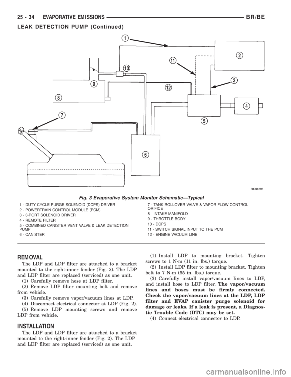
REMOVAL
The LDP and LDP filter are attached to a bracket
mounted to the right-inner fender (Fig. 2). The LDP
and LDP filter are replaced (serviced) as one unit.
(1) Carefully remove hose at LDP filter.
(2) Remove LDP filter mounting bolt and remove
from vehicle.
(3) Carefully remove vapor/vacuum lines at LDP.
(4) Disconnect electrical connector at LDP (Fig. 2).
(5) Remove LDP mounting screws and remove
LDP from vehicle.
INSTALLATION
The LDP and LDP filter are attached to a bracket
mounted to the right-inner fender (Fig. 2). The LDP
and LDP filter are replaced (serviced) as one unit.(1) Install LDP to mounting bracket. Tighten
screws to 1 N´m (11 in. lbs.) torque.
(2) Install LDP filter to mounting bracket. Tighten
bolt to 7 N´m (65 in. lbs.) torque.
(3) Carefully install vapor/vacuum lines to LDP,
and install hose to LDP filter.The vapor/vacuum
lines and hoses must be firmly connected.
Check the vapor/vacuum lines at the LDP, LDP
filter and EVAP canister purge solenoid for
damage or leaks. If a leak is present, a Diagnos-
tic Trouble Code (DTC) may be set.
(4) Connect electrical connector to LDP.
Fig. 3 Evaporative System Monitor SchematicÐTypical
1 - DUTY CYCLE PURGE SOLENOID (DCPS) DRIVER
2 - POWERTRAIN CONTROL MODULE (PCM)
3 - 3-PORT SOLENOID DRIVER
4 - REMOTE FILTER
5 - COMBINED CANISTER VENT VALVE & LEAK DETECTION
PUMP
6 - CANISTER7 - TANK ROLLOVER VALVE & VAPOR FLOW CONTROL
ORIFICE
8 - INTAKE MANIFOLD
9 - THROTTLE BODY
10 - DCPS
11 - SWITCH SIGNAL INPUT TO THE PCM
12 - ENGINE VACUUM LINE
25 - 34 EVAPORATIVE EMISSIONSBR/BE
LEAK DETECTION PUMP (Continued)
Page 2826 of 2889
NEW VEHICLE PREPARATION
TABLE OF CONTENTS
page page
INTRODUCTION
DESCRIPTION............................1
RECEIVING
INSPECTION.............................3
UNDER HOOD
INSPECTION.............................4
UNDER VEHICLE
INSPECTION.............................8
INSTALLATION...........................10
EXTERIOR
INSPECTION............................10
BODY INTERIOR
INSPECTION............................12
INSTALLATION...........................14
ROAD TEST
DESCRIPTION...........................15INSPECTION............................15
PRE DELIVERY STORAGE
DESCRIPTION...........................19
STANDARD PROCEDURE..................20
PRE DELIVERY STORAGE................20
PROGRAMMABLE ELECTRONIC FEATURES
DESCRIPTION...........................20
OPERATION.............................20
APPEARANCE TIPS
CLEANING..............................21
FINAL STEPS
STANDARD PROCEDURE..................22
NEW VEHICLE PREPARATION FORM.......22
OWNER CHECK OUT....................22
INSPECTION............................22
INTRODUCTION
DESCRIPTION - THE IMPORTANCE OF
CAREFUL NEW VEHICLE PREPARATION
Today, the automobile industry is more competitive
than it has been for decades. Automakers around the
world, including DaimlerChrysler, have made tre-
mendous improvements in the quality of their vehi-
cles.
As a result, customer expectations have also risen.
Today's customers are more particular about their
vehicles than ever before. The result is that problems
once regarded as insignificant (such as a squeak or
rattle) can now make the difference between a repeat
customer and one who never purchases another vehi-
cle from you dealership or another DaimlerChrysler
Corporation product.
As a technician preparing a new car or truck for
delivery, you are the final step in the entire quality
process. Your inspection is the final opportunity to
detect any flaws that would disappoint the customer.
Your efforts will reflect upon the thousands of men
and women who design, engineer and build Daimler-
Chrysler products as well as upon your dealership
and on yourself as a competent, conscientious techni-
cian.
As manufacturing quality has improved, prep pro-
cedures have come to serve as additional quality
checks. However, there are several compelling rea-
sons for careful new vehicle preparation.²Safety-You assure the customer that his or her
new vehicle meets all federal safety standards.
²Emissions Controls-When your customers are
assured that their new cars meet emissions stan-
dards, they will know that they are contributing to
cleaner air and helping control pollution.
²Customer Satisfaction-First impressions are very
important on a new vehicle. Careful new vehicle
preparation will impress your customer.
²Competition-It is common knowledge in the
industry that the availability of efficient service is
one of the decisive factors in determining which cars
will sell. A vehicle delivered to your customers in
first class condition, inside and out, will bring them
back to the dealership for the kind of service you
have led them to expect and for their next new car.
This information outlines service procedures which
will ensure that DaimlerChrysler Corporation vehi-
cles are ready for delivery to the customer when they
are complete. These procedures follow a logical order,
from a careful underhood inspection, to the moment
when you complete the warranty certificate and turn
the keys over to your customer.
When you have completed the procedures described
in this information, both you and your customer will
be assured that his or her new vehicle will perform
as expected.
USING THE MANUAL
This guide to new vehicle preparation covers all
items on the New Vehicle Preparation Form (Fig. 1).
BR/BENEW VEHICLE PREPARATION 30 - 1
Page 2829 of 2889
UNDER HOOD
INSPECTION - HOOD LATCH/SAFETY CATCH
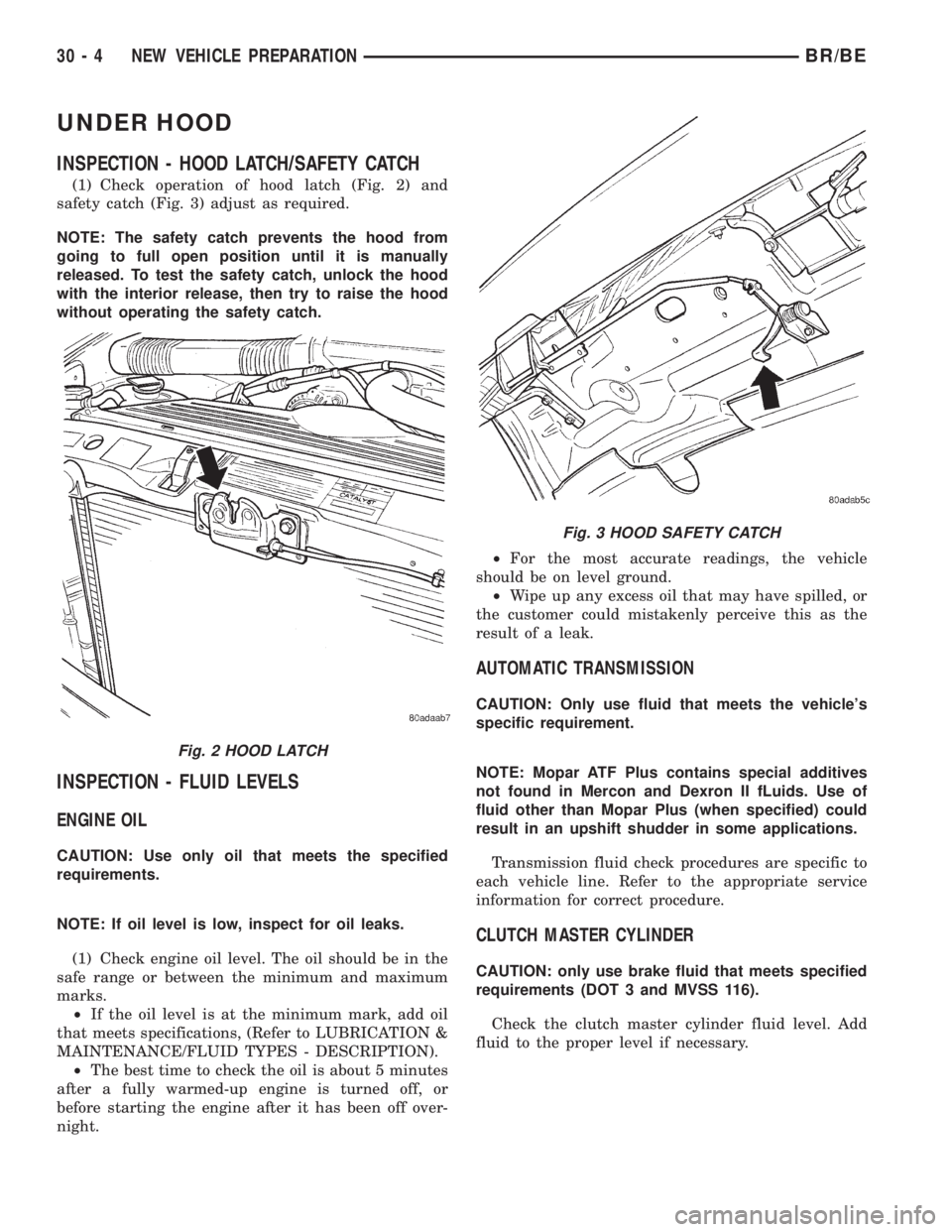
(1) Check operation of hood latch (Fig. 2) and
safety catch (Fig. 3) adjust as required.
NOTE: The safety catch prevents the hood from
going to full open position until it is manually
released. To test the safety catch, unlock the hood
with the interior release, then try to raise the hood
without operating the safety catch.
INSPECTION - FLUID LEVELS
ENGINE OIL
CAUTION: Use only oil that meets the specified
requirements.
NOTE: If oil level is low, inspect for oil leaks.
(1) Check engine oil level. The oil should be in the
safe range or between the minimum and maximum
marks.
²If the oil level is at the minimum mark, add oil
that meets specifications, (Refer to LUBRICATION &
MAINTENANCE/FLUID TYPES - DESCRIPTION).
²The best time to check the oil is about 5 minutes
after a fully warmed-up engine is turned off, or
before starting the engine after it has been off over-
night.²For the most accurate readings, the vehicle
should be on level ground.
²Wipe up any excess oil that may have spilled, or
the customer could mistakenly perceive this as the
result of a leak.
AUTOMATIC TRANSMISSION
CAUTION: Only use fluid that meets the vehicle's
specific requirement.
NOTE: Mopar ATF Plus contains special additives
not found in Mercon and Dexron II fLuids. Use of
fluid other than Mopar Plus (when specified) could
result in an upshift shudder in some applications.
Transmission fluid check procedures are specific to
each vehicle line. Refer to the appropriate service
information for correct procedure.
CLUTCH MASTER CYLINDER
CAUTION: only use brake fluid that meets specified
requirements (DOT 3 and MVSS 116).
Check the clutch master cylinder fluid level. Add
fluid to the proper level if necessary.
Fig. 2 HOOD LATCH
Fig. 3 HOOD SAFETY CATCH
30 - 4 NEW VEHICLE PREPARATIONBR/BE
Page 2831 of 2889
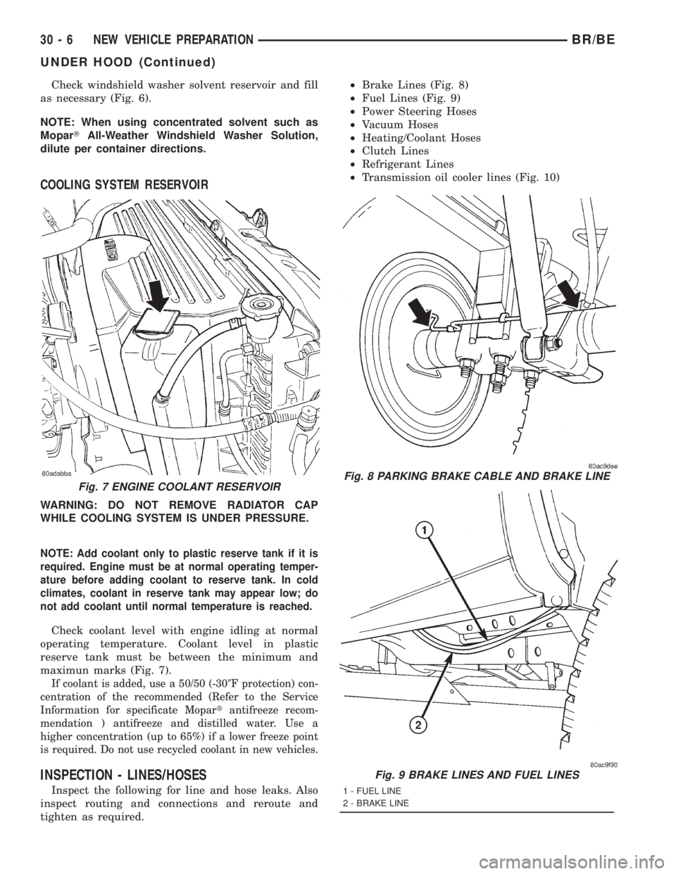
Check windshield washer solvent reservoir and fill
as necessary (Fig. 6).
NOTE: When using concentrated solvent such as
MoparTAll-Weather Windshield Washer Solution,
dilute per container directions.
COOLING SYSTEM RESERVOIR
WARNING: DO NOT REMOVE RADIATOR CAP
WHILE COOLING SYSTEM IS UNDER PRESSURE.
NOTE: Add coolant only to plastic reserve tank if it is
required. Engine must be at normal operating temper-
ature before adding coolant to reserve tank. In cold
climates, coolant in reserve tank may appear low; do
not add coolant until normal temperature is reached.
Check coolant level with engine idling at normal
operating temperature. Coolant level in plastic
reserve tank must be between the minimum and
maximun marks (Fig. 7).
If coolant is added, use a 50/50 (-309F protection) con-
centration of the recommended (Refer to the Service
Information for specificate Mopartantifreeze recom-
mendation ) antifreeze and distilled water. Use a
higher concentration (up to 65%) if a lower freeze point
is required. Do not use recycled coolant in new vehicles.
INSPECTION - LINES/HOSES
Inspect the following for line and hose leaks. Also
inspect routing and connections and reroute and
tighten as required.²Brake Lines (Fig. 8)
²Fuel Lines (Fig. 9)
²Power Steering Hoses
²Vacuum Hoses
²Heating/Coolant Hoses
²Clutch Lines
²Refrigerant Lines
²Transmission oil cooler lines (Fig. 10)
Fig. 7 ENGINE COOLANT RESERVOIRFig. 8 PARKING BRAKE CABLE AND BRAKE LINE
Fig. 9 BRAKE LINES AND FUEL LINES
1 - FUEL LINE
2 - BRAKE LINE
30 - 6 NEW VEHICLE PREPARATIONBR/BE
UNDER HOOD (Continued)