2001 DODGE RAM engine coolant
[x] Cancel search: engine coolantPage 347 of 2889
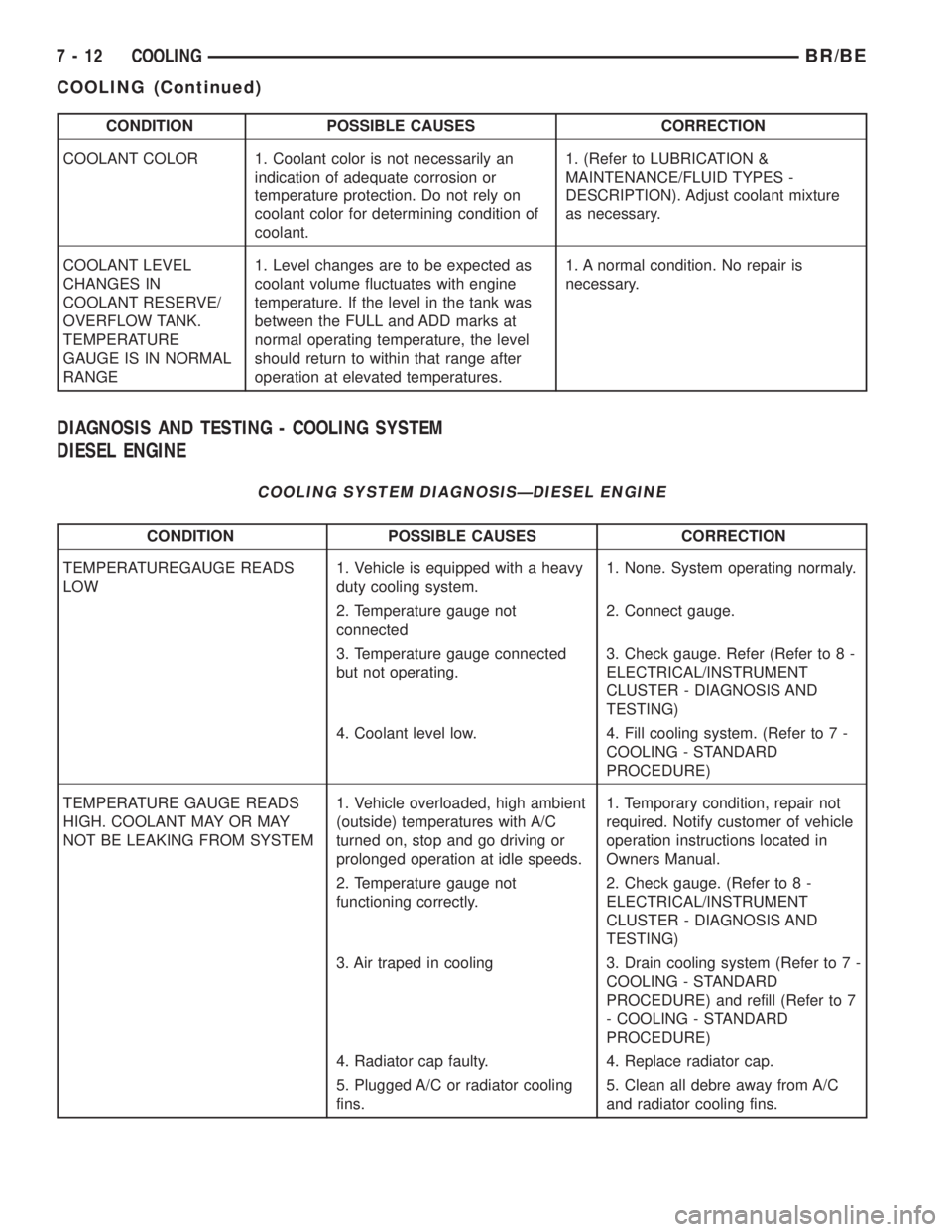
CONDITION POSSIBLE CAUSES CORRECTION
COOLANT COLOR 1. Coolant color is not necessarily an
indication of adequate corrosion or
temperature protection. Do not rely on
coolant color for determining condition of
coolant.1. (Refer to LUBRICATION &
MAINTENANCE/FLUID TYPES -
DESCRIPTION). Adjust coolant mixture
as necessary.
COOLANT LEVEL
CHANGES IN
COOLANT RESERVE/
OVERFLOW TANK.
TEMPERATURE
GAUGE IS IN NORMAL
RANGE1. Level changes are to be expected as
coolant volume fluctuates with engine
temperature. If the level in the tank was
between the FULL and ADD marks at
normal operating temperature, the level
should return to within that range after
operation at elevated temperatures.1. A normal condition. No repair is
necessary.
DIAGNOSIS AND TESTING - COOLING SYSTEM
DIESEL ENGINE
COOLING SYSTEM DIAGNOSISÐDIESEL ENGINE
CONDITION POSSIBLE CAUSES CORRECTION
TEMPERATUREGAUGE READS
LOW1. Vehicle is equipped with a heavy
duty cooling system.1. None. System operating normaly.
2. Temperature gauge not
connected2. Connect gauge.
3. Temperature gauge connected
but not operating.3. Check gauge. Refer (Refer to 8 -
ELECTRICAL/INSTRUMENT
CLUSTER - DIAGNOSIS AND
TESTING)
4. Coolant level low. 4. Fill cooling system. (Refer to 7 -
COOLING - STANDARD
PROCEDURE)
TEMPERATURE GAUGE READS
HIGH. COOLANT MAY OR MAY
NOT BE LEAKING FROM SYSTEM1. Vehicle overloaded, high ambient
(outside) temperatures with A/C
turned on, stop and go driving or
prolonged operation at idle speeds.1. Temporary condition, repair not
required. Notify customer of vehicle
operation instructions located in
Owners Manual.
2. Temperature gauge not
functioning correctly.2. Check gauge. (Refer to 8 -
ELECTRICAL/INSTRUMENT
CLUSTER - DIAGNOSIS AND
TESTING)
3. Air traped in cooling 3. Drain cooling system (Refer to 7 -
COOLING - STANDARD
PROCEDURE) and refill (Refer to 7
- COOLING - STANDARD
PROCEDURE)
4. Radiator cap faulty. 4. Replace radiator cap.
5. Plugged A/C or radiator cooling
fins.5. Clean all debre away from A/C
and radiator cooling fins.
7 - 12 COOLINGBR/BE
COOLING (Continued)
Page 348 of 2889

CONDITION POSSIBLE CAUSES CORRECTION
6. Coolant mixture incorrect. 6. Drain cooling system (Refer to 7 -
COOLING - STANDARD
PROCEDURE) refill with correct
mixture (Refer to 7 - COOLING -
STANDARD PROCEDURE).
7. Thermostat stuck shut. 7. Replace thermostat.
8. Bug screen or winter front being
used.8. Remove bug screen or winter
front.
9. Viscous fan drive not operating
properly.9. Check viscous fan (Refer to 7 -
COOLING/ENGINE/FAN DRIVE
VISCOUS CLUTCH - DIAGNOSIS
AND TESTING)
10. Cylinder head gasket leaking. 10. Check for leaking head gaskets
(Refer to 7 - COOLING -
DIAGNOSIS AND TESTING).
11. Heater core leaking. 11. Replace heater core.
12. cooling system hoses leaking. 12. Tighten clamps or Replace
hoses.
13. Brakes dragging. 13. Check brakes. (Refer to 5 -
BRAKES/HYDRAULIC/
MECHANICAL - DIAGNOSIS AND
TESTING)
TEMPERATURE GAUGE READING
INCONSISTENT ( ERRATIC,
CYCLES OR FLUCTUATES)1. Heavy duty cooling system,
extream cold ambient (outside)
temperature or heater blower motor
in high position.1. None. System operating normaly.
2. Temperature gauge or gauge
sensor defective.2. Check gauge. (Refer to 8 -
ELECTRICAL/INSTRUMENT
CLUSTER - DIAGNOSIS AND
TESTING)
3. Temporary heavy usage or load. 3. None. Normal condition.
4. Air traped in cooling system. 4. Fill cooling system (Refer to 7 -
COOLING - STANDARD
PROCEDURE).
5. Water pump 5. Replace water pump.
6. Air leak on suction side of water
pump.6. Check for leak. (Refer to 7 -
COOLING - DIAGNOSIS AND
TESTING)
RADIATOR CAP LEAKING STEAM
AND /OR COOLANT INTO
RESERVOIR BOTTLE.
(TEMPERATURE GAUGE MAY
READ HIGH)1. Radiator cap defective. 1. Replace radiator cap.
2. Radiator neck surface damaged. 2. Replace radiator.
BR/BECOOLING 7 - 13
COOLING (Continued)
Page 349 of 2889
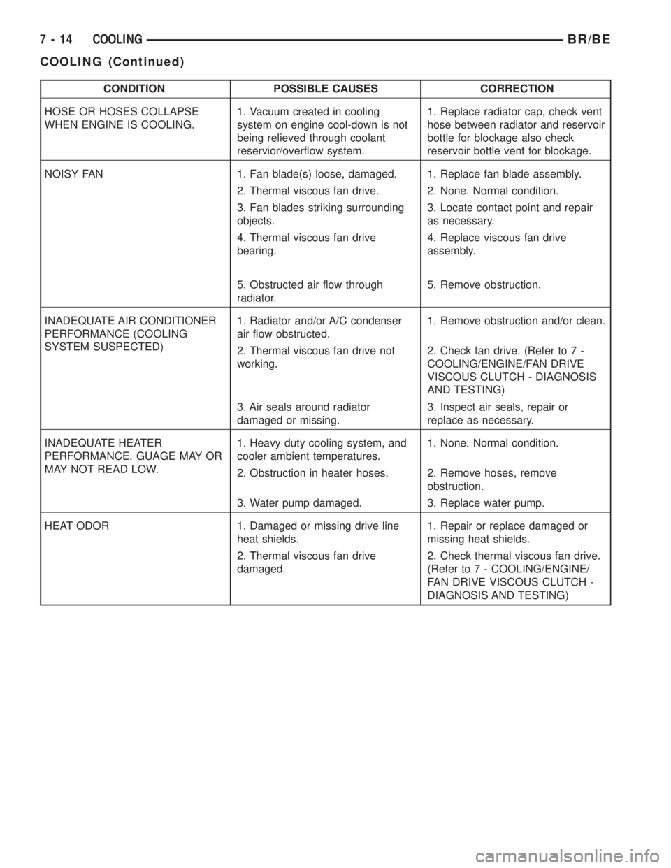
CONDITION POSSIBLE CAUSES CORRECTION
HOSE OR HOSES COLLAPSE
WHEN ENGINE IS COOLING.1. Vacuum created in cooling
system on engine cool-down is not
being relieved through coolant
reservior/overflow system.1. Replace radiator cap, check vent
hose between radiator and reservoir
bottle for blockage also check
reservoir bottle vent for blockage.
NOISY FAN 1. Fan blade(s) loose, damaged. 1. Replace fan blade assembly.
2. Thermal viscous fan drive. 2. None. Normal condition.
3. Fan blades striking surrounding
objects.3. Locate contact point and repair
as necessary.
4. Thermal viscous fan drive
bearing.4. Replace viscous fan drive
assembly.
5. Obstructed air flow through
radiator.5. Remove obstruction.
INADEQUATE AIR CONDITIONER
PERFORMANCE (COOLING
SYSTEM SUSPECTED)1. Radiator and/or A/C condenser
air flow obstructed.1. Remove obstruction and/or clean.
2. Thermal viscous fan drive not
working.2. Check fan drive. (Refer to 7 -
COOLING/ENGINE/FAN DRIVE
VISCOUS CLUTCH - DIAGNOSIS
AND TESTING)
3. Air seals around radiator
damaged or missing.3. Inspect air seals, repair or
replace as necessary.
INADEQUATE HEATER
PERFORMANCE. GUAGE MAY OR
MAY NOT READ LOW.1. Heavy duty cooling system, and
cooler ambient temperatures.1. None. Normal condition.
2. Obstruction in heater hoses. 2. Remove hoses, remove
obstruction.
3. Water pump damaged. 3. Replace water pump.
HEAT ODOR 1. Damaged or missing drive line
heat shields.1. Repair or replace damaged or
missing heat shields.
2. Thermal viscous fan drive
damaged.2. Check thermal viscous fan drive.
(Refer to 7 - COOLING/ENGINE/
FAN DRIVE VISCOUS CLUTCH -
DIAGNOSIS AND TESTING)
7 - 14 COOLINGBR/BE
COOLING (Continued)
Page 350 of 2889
STANDARD PROCEDUREÐDRAINING
COOLING SYSTEM 3.9L/5.2L/5.9L/8.0L
ENGINES
WARNING: DO NOT REMOVE CYLINDER BLOCK
DRAIN PLUGS OR LOOSEN RADIATOR DRAIN-
COCK WITH SYSTEM HOT AND UNDER PRESSURE.
SERIOUS BURNS FROM COOLANT CAN OCCUR.
DO NOT WASTE reusable coolant. If solution is
clean, drain coolant into a clean container for reuse.
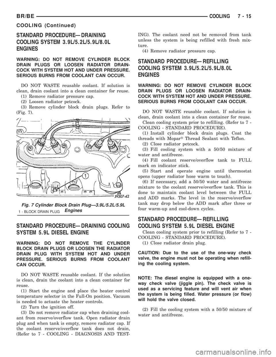
(1) Remove radiator pressure cap.
(2) Loosen radiator petcock.
(3) Remove cylinder block drain plugs. Refer to
(Fig. 7).
STANDARD PROCEDUREÐDRAINING COOLING
SYSTEM 5.9L DIESEL ENGINE
WARNING: DO NOT REMOVE THE CYLINDER
BLOCK DRAIN PLUGS OR LOOSEN THE RADIATOR
DRAIN PLUG WITH SYSTEM HOT AND UNDER
PRESSURE. SERIOUS BURNS FROM COOLANT
CAN OCCUR.
DO NOT WASTE reusable coolant. If the solution
is clean, drain the coolant into a clean container for
reuse.
(1) Start the engine and place the heater control
temperature selector in the Full-On position. Vacuum
is needed to actuate the heater controls.
(2) Turn the ignition off.
(3) Do not remove radiator cap when draining cool-
ant from reserve/overflow tank. Open radiator drain
plug and when tank is empty, remove radiator cap. If
the coolant reserve/overflow tank does not drain,
(Refer to 7 - COOLING - DIAGNOSIS AND TEST-ING). The coolant need not be removed from tank
unless the system is being refilled with fresh mix-
ture.
(4) Remove radiator pressure cap.
STANDARD PROCEDUREÐREFILLING
COOLING SYSTEM 3.9L/5.2L/5.9L/8.0L
ENGINES
WARNING: DO NOT REMOVE CYLINDER BLOCK
DRAIN PLUGS OR LOOSEN RADIATOR DRAIN-
COCK WITH SYSTEM HOT AND UNDER PRESSURE.
SERIOUS BURNS FROM COOLANT CAN OCCUR.
DO NOT WASTE reusable coolant. If solution is
clean, drain coolant into a clean container for reuse.
Clean cooling system prior to refilling. (Refer to 7 -
COOLING - STANDARD PROCEDURE).
(1) Install cylinder block drain plugs. Coat the
threads with MopartThread Sealant with Teflon.
(2) Close radiator petcock.
(3) Fill cooling system with a 50/50 mixture of
water and antifreeze.
(4) Fill coolant reserve/overflow tank to FULL
mark on indicator stick.
(5) Start and operate engine until thermostat
opens (upper radiator hose warm to touch).
(6) If necessary, add a 50/50 water and antifreeze
mixture to the coolant reserve/overflow tank. This is
done to maintain coolant level between the FULL
and ADD marks. The level in the reserve/overflow
tank may drop below the ADD mark after three or
four warm-up and cool-down cycles.
STANDARD PROCEDUREÐREFILLING
COOLING SYSTEM 5.9L DIESEL ENGINE
Clean cooling system prior to refilling (Refer to 7 -
COOLING - STANDARD PROCEDURE).
(1) Close radiator drain plug.
CAUTION: Due to the use of the one-way check
valve, the engine must not be operating when refill-
ing the cooling system.
NOTE: The diesel engine is equipped with a one-
way check valve (jiggle pin). The check valve is
used as a servicing feature and will vent air when
the system is being filled. Water pressure (or flow)
will hold the valve closed.
(2) Fill the cooling system with a 50/50 mixture of
water and antifreeze.
Fig. 7 Cylinder Block Drain PlugÐ3.9L/5.2L/5.9L
Engines
1 - BLOCK DRAIN PLUG
BR/BECOOLING 7 - 15
COOLING (Continued)
Page 351 of 2889
(3) Fill coolant reserve/overflow tank to the FULL
mark.
(4) Start and operate engine until thermostat
opens. Upper radiator hose should be warm to touch.
(5) If necessary, add 50/50 water and antifreeze
mixture to the coolant reserve/overflow tank to main-
tain coolant level. This level should be between the
ADD and FULL marks. The level in the reserve/over-
flow tank may drop below the ADD mark after three
or four warm-up and cool-down cycles.
STANDARD PROCEDUREÐADDING
ADDITIONAL COOLANT
Do not remove radiator cap to add coolant to
system.When adding coolant to maintain correct
level, do so at coolant reserve/overflow tank. Use a
50/50 mixture of ethylene glycol antifreeze containing
Alugard 340-2yand low mineral content water.
Remove radiator cap only for testing or when refill-
ing system after service. Removing cap unnecessarily
can cause loss of coolant and allow air to enter sys-
tem, which produces corrosion.
STANDARD PROCEDUREÐCOOLANT LEVEL
CHECK
NOTE: Do not remove radiator cap for routine cool-
ant level inspections. The coolant level can be
checked at coolant recovery bottle .
The coolant reserve/overflow system provides a
quick method for determining coolant level without
removing radiator pressure cap. With engine not run-
ning, open the coolant recovery bottle cap and
remove coolant level indicator dipstick to observe
coolant level in coolant recovery bottle. The coolant
level should be between ADD and FULL marks. If
the coolant level is at or below the ADD mark, fill
the recovery bottle with a 50/50 mixture of antifreeze
and water ONE QUART AT A TIME. Repeat this pro-
cedure until the coolant level is at the FULL mark
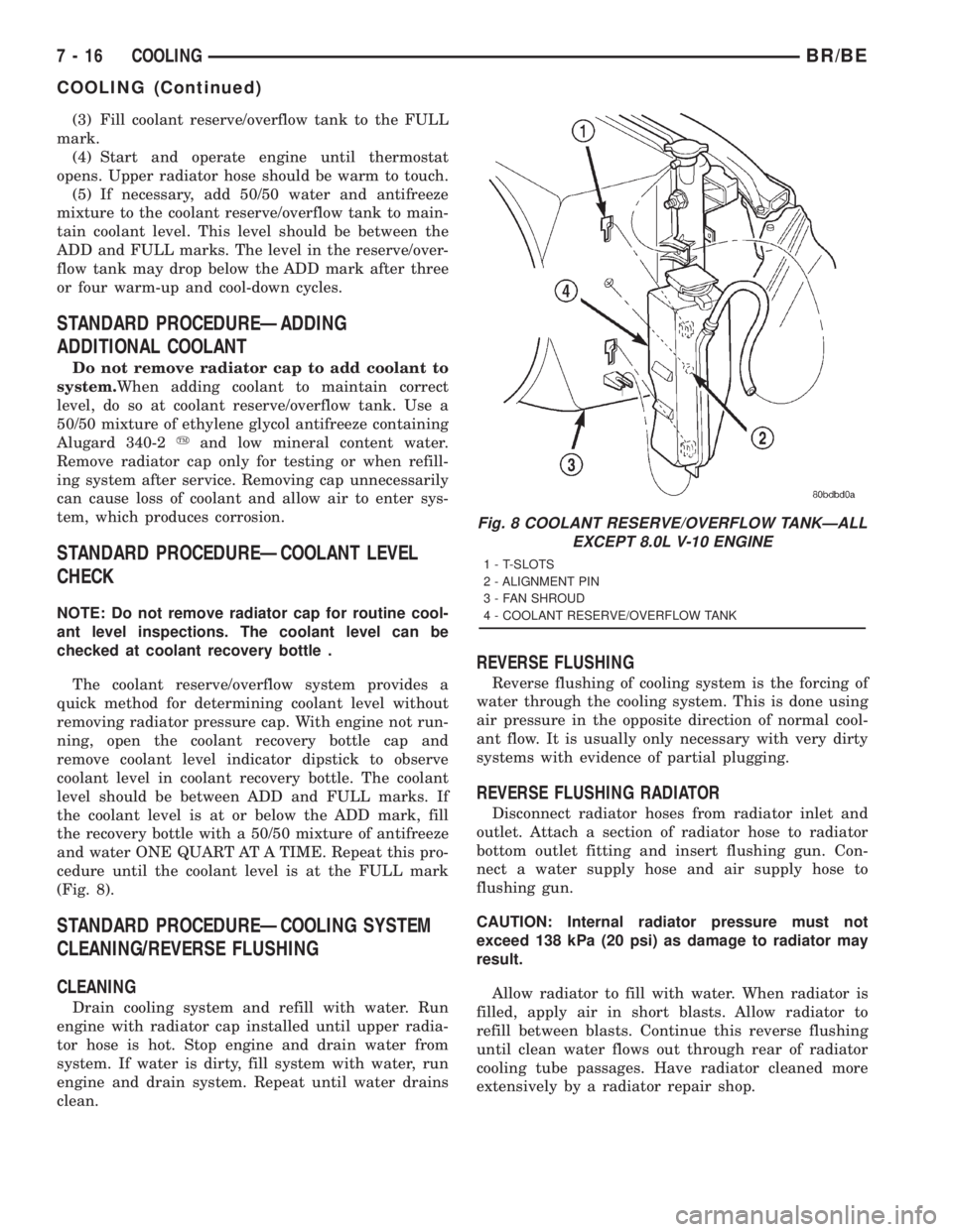
(Fig. 8).
STANDARD PROCEDUREÐCOOLING SYSTEM
CLEANING/REVERSE FLUSHING
CLEANING
Drain cooling system and refill with water. Run
engine with radiator cap installed until upper radia-
tor hose is hot. Stop engine and drain water from
system. If water is dirty, fill system with water, run
engine and drain system. Repeat until water drains
clean.
REVERSE FLUSHING
Reverse flushing of cooling system is the forcing of
water through the cooling system. This is done using
air pressure in the opposite direction of normal cool-
ant flow. It is usually only necessary with very dirty
systems with evidence of partial plugging.
REVERSE FLUSHING RADIATOR
Disconnect radiator hoses from radiator inlet and
outlet. Attach a section of radiator hose to radiator
bottom outlet fitting and insert flushing gun. Con-
nect a water supply hose and air supply hose to
flushing gun.
CAUTION: Internal radiator pressure must not
exceed 138 kPa (20 psi) as damage to radiator may
result.
Allow radiator to fill with water. When radiator is
filled, apply air in short blasts. Allow radiator to
refill between blasts. Continue this reverse flushing
until clean water flows out through rear of radiator
cooling tube passages. Have radiator cleaned more
extensively by a radiator repair shop.
Fig. 8 COOLANT RESERVE/OVERFLOW TANKÐALL
EXCEPT 8.0L V-10 ENGINE
1 - T-SLOTS
2 - ALIGNMENT PIN
3 - FAN SHROUD
4 - COOLANT RESERVE/OVERFLOW TANK
7 - 16 COOLINGBR/BE
COOLING (Continued)
Page 352 of 2889
REVERSE FLUSHING ENGINE
Drain cooling system. Remove thermostat housing
and thermostat. Install thermostat housing. Discon-
nect radiator upper hose from radiator and attach
flushing gun to hose. Disconnect radiator lower hose
from water pump and attach a lead-away hose to
water pump inlet fitting.
CAUTION: On vehicles equipped with a heater water
control valve, be sure heater control valve is closed
(heat off). This will prevent coolant flow with scale
and other deposits from entering heater core.
Connect water supply hose and air supply hose to
flushing gun. Allow engine to fill with water. When
engine is filled, apply air in short blasts, allowing
system to fill between air blasts. Continue until clean
water flows through the lead away hose.
Remove lead away hose, flushing gun, water sup-
ply hose and air supply hose. Remove thermostat
housing and install thermostat. Install thermostat
housing with a replacement gasket. Refer to Thermo-
stat Replacement. Connect radiator hoses. Refill cool-
ing system with correct antifreeze/water mixture.
Refer to Refilling the Cooling System.
CHEMICAL CLEANING
In some instances, use a radiator cleaner (Mopar
Radiator Kleen or equivalent) before flushing. This
will soften scale and other deposits and aid flushing
operation.
CAUTION: Follow manufacturers instructions when
using these products.
STANDARD PROCEDUREÐCOOLANT
SELECTION-ADDITIVES
The presence of aluminum components in the cool-
ing system requires strict corrosion protection. Main-
tain coolant at specified level with a mixture of
ethylene glycol based antifreeze and water. If coolant
becomes contaminated or looses color, drain and flush
cooling system and fill with correctly mixed solution.
CAUTION: Do not use coolant additives that are
claimed to improve engine cooling.
SPECIFICATIONS
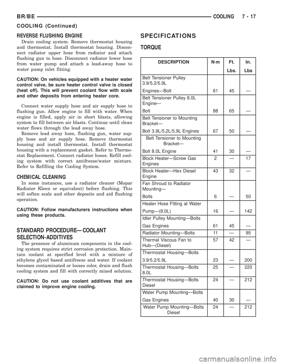
TORQUE
DESCRIPTION N´m Ft. In.
Lbs. Lbs
Belt Tensioner Pulley
3.9/5.2/5.9L
EnginesÐBolt 61 45 Ð
Belt Tensioner Pulley 8.0L
EngineÐ
Bolt 88 65 Ð
Belt Tensioner to Mounting
BracketÐ
Bolt 3.9L/5.2L/5.9L Engines 67 50 Ð
Belt Tensioner to Mounting
BracketÐ
Bolt 8.0L Engine 41 30 Ð
Block HeaterÐScrew Gas
Engines2Ð17
Block HeaterÐHex Diesel
Engine43 32 Ð
Fan Shroud to Radiator
MountingÐ
Bolts 6 Ð 50
Heater Hose Fitting at Water
PumpÐ(8.0L) 16 Ð 142
Idler Pulley MountingÐBolts
Gas Engines 61 45 Ð
Radiator MountingÐBolts 11 Ð 95
Thermal Viscous Fan to
HubÐ(Diesel)57 42 Ð
Thermostat HousingÐBolts
3.9/5.2/5.9L 23 Ð 200
Thermostat HousingÐBolts
8.0L25 Ð 220
Thermostat HousingÐBolts
Diesel24 Ð 212
Water Pump MountingÐBolts
Gas Engines 40 30 Ð
Water Pump MountingÐBolts
Diesel24 Ð 212
BR/BECOOLING 7 - 17
COOLING (Continued)
Page 374 of 2889

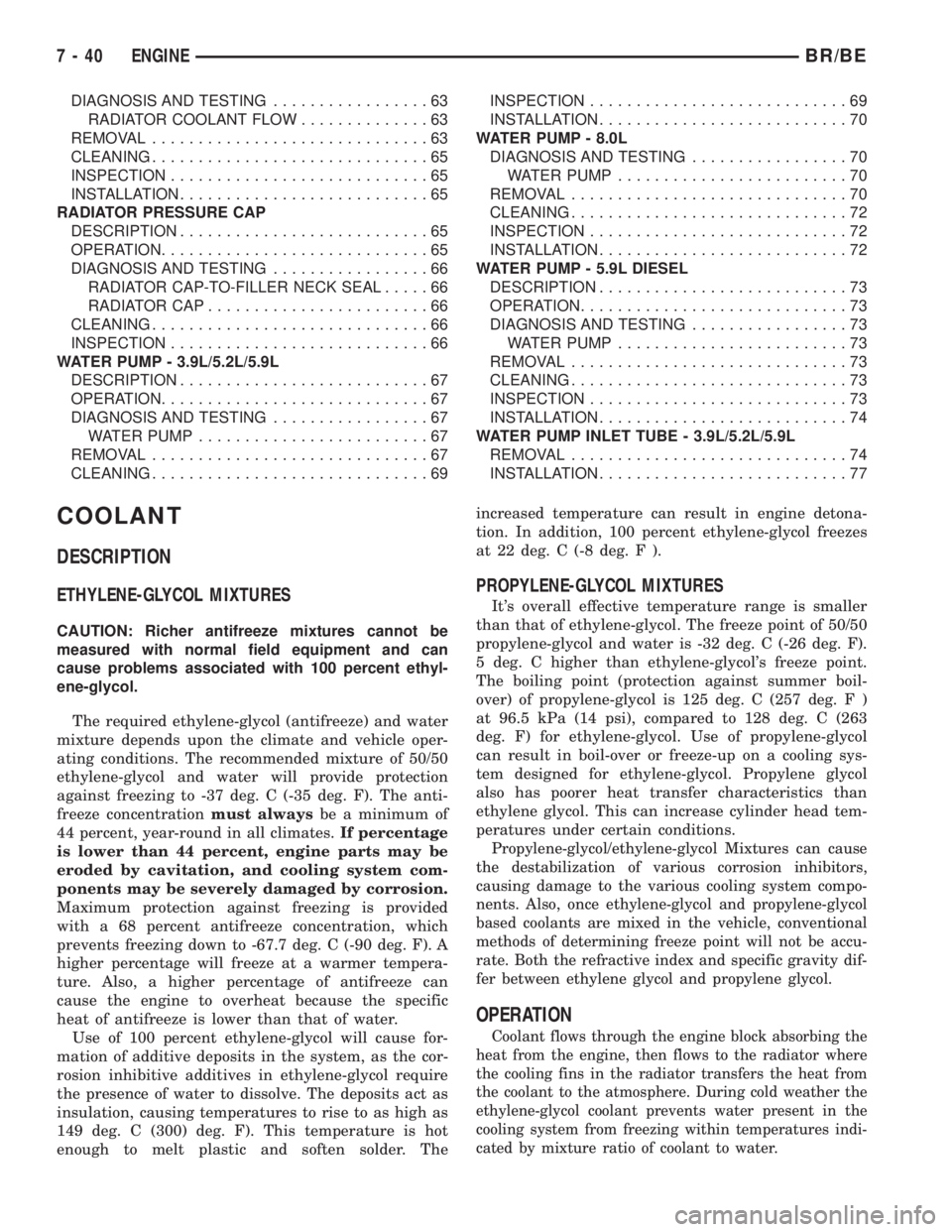
ENGINE
TABLE OF CONTENTS
page page
COOLANT
DESCRIPTION...........................40
OPERATION.............................40
COOLANT RECOVERY CONTAINER - 3.9L/5.2L/
5.9L/5.9L DIESEL
DESCRIPTION...........................41
OPERATION.............................41
REMOVAL..............................41
INSTALLATION...........................41
COOLANT RECOVERY CONTAINER - 8.0L
DESCRIPTION...........................42
OPERATION.............................42
RADIATOR FAN - 3.9L/5.2L/5.9L/8.0L
REMOVAL..............................42
CLEANING..............................43
INSPECTION............................43
INSTALLATION...........................43
RADIATOR FAN - 5.9L DIESEL
REMOVAL..............................44
CLEANING..............................44
INSPECTION............................44
INSTALLATION...........................45
ENGINE BLOCK HEATER - 3.9L/5.2L/5.9L
DESCRIPTION...........................45
OPERATION.............................45
REMOVAL..............................45
INSTALLATION...........................45
ENGINE BLOCK HEATER - 8.0L
DESCRIPTION...........................46
OPERATION.............................46
REMOVAL..............................46
INSTALLATION...........................46
ENGINE BLOCK HEATER - 5.9L DIESEL
DESCRIPTION...........................47
OPERATION.............................47
REMOVAL..............................47
INSTALLATION...........................47
ENGINE COOLANT TEMP SENSOR - 3.9L/5.2L/
5.9L
DESCRIPTION...........................48
OPERATION.............................48
REMOVAL..............................48
INSTALLATION...........................48
ENGINE COOLANT THERMOSTAT - 3.9L/5.2L/
5.9L
DESCRIPTION...........................49
OPERATION.............................49
DIAGNOSIS AND TESTING.................49
THERMOSTAT.........................49REMOVAL..............................49
INSTALLATION...........................50
ENGINE COOLANT THERMOSTAT - 8.0L
DESCRIPTION...........................52
OPERATION.............................52
DIAGNOSIS AND TESTING.................52
THERMOSTAT.........................52
REMOVAL..............................52
INSTALLATION...........................53
ENGINE COOLANT THERMOSTAT - 5.9L
DIESEL
DESCRIPTION...........................54
OPERATION.............................54
DIAGNOSIS AND TESTING.................54
THERMOSTAT.........................54
REMOVAL..............................55
INSTALLATION...........................55
FAN DRIVE VISCOUS CLUTCH - 3.9L/5.2L/5.9L/
8.0L
DESCRIPTION...........................56
OPERATION.............................56
DIAGNOSIS AND TESTING.................56
VISCOUS FAN DRIVE...................56
FAN DRIVE VISCOUS CLUTCH - 5.9L DIESEL
DESCRIPTION...........................57
OPERATION.............................57
DIAGNOSIS AND TESTING.................58
VISCOUS FAN DRIVE...................58
RADIATOR - 3.9L/5.2L/5.9L
DESCRIPTION...........................59
OPERATION.............................59
DIAGNOSIS AND TESTING.................59
RADIATOR COOLANT FLOW..............59
REMOVAL..............................59
CLEANING..............................60
INSPECTION............................61
INSTALLATION...........................61
RADIATOR - 8.0L
DESCRIPTION...........................61
OPERATION.............................61
DIAGNOSIS AND TESTING.................61
RADIATOR COOLANT FLOW..............61
REMOVAL..............................62
CLEANING..............................62
INSPECTION............................62
INSTALLATION...........................63
RADIATOR - 5.9L DIESEL
DESCRIPTION...........................63
OPERATION.............................63
BR/BEENGINE 7 - 39
Page 375 of 2889
DIAGNOSIS AND TESTING.................63
RADIATOR COOLANT FLOW..............63
REMOVAL..............................63
CLEANING..............................65
INSPECTION............................65
INSTALLATION...........................65
RADIATOR PRESSURE CAP
DESCRIPTION...........................65
OPERATION.............................65
DIAGNOSIS AND TESTING.................66
RADIATOR CAP-TO-FILLER NECK SEAL.....66
RADIATOR CAP........................66
CLEANING..............................66
INSPECTION............................66
WATER PUMP - 3.9L/5.2L/5.9L
DESCRIPTION...........................67
OPERATION.............................67
DIAGNOSIS AND TESTING.................67
WATER PUMP.........................67
REMOVAL..............................67
CLEANING..............................69INSPECTION............................69
INSTALLATION...........................70
WATER PUMP - 8.0L
DIAGNOSIS AND TESTING.................70
WATER PUMP.........................70
REMOVAL..............................70
CLEANING..............................72
INSPECTION............................72
INSTALLATION...........................72
WATER PUMP - 5.9L DIESEL
DESCRIPTION...........................73
OPERATION.............................73
DIAGNOSIS AND TESTING.................73
WATER PUMP.........................73
REMOVAL..............................73
CLEANING..............................73
INSPECTION............................73
INSTALLATION...........................74
WATER PUMP INLET TUBE - 3.9L/5.2L/5.9L
REMOVAL..............................74
INSTALLATION...........................77
COOLANT
DESCRIPTION
ETHYLENE-GLYCOL MIXTURES
CAUTION: Richer antifreeze mixtures cannot be
measured with normal field equipment and can
cause problems associated with 100 percent ethyl-
ene-glycol.
The required ethylene-glycol (antifreeze) and water
mixture depends upon the climate and vehicle oper-
ating conditions. The recommended mixture of 50/50
ethylene-glycol and water will provide protection
against freezing to -37 deg. C (-35 deg. F). The anti-
freeze concentrationmust alwaysbe a minimum of
44 percent, year-round in all climates.If percentage
is lower than 44 percent, engine parts may be
eroded by cavitation, and cooling system com-
ponents may be severely damaged by corrosion.
Maximum protection against freezing is provided
with a 68 percent antifreeze concentration, which
prevents freezing down to -67.7 deg. C (-90 deg. F). A
higher percentage will freeze at a warmer tempera-
ture. Also, a higher percentage of antifreeze can
cause the engine to overheat because the specific
heat of antifreeze is lower than that of water.
Use of 100 percent ethylene-glycol will cause for-
mation of additive deposits in the system, as the cor-
rosion inhibitive additives in ethylene-glycol require
the presence of water to dissolve. The deposits act as
insulation, causing temperatures to rise to as high as
149 deg. C (300) deg. F). This temperature is hot
enough to melt plastic and soften solder. Theincreased temperature can result in engine detona-
tion. In addition, 100 percent ethylene-glycol freezes
at 22 deg. C (-8 deg. F ).
PROPYLENE-GLYCOL MIXTURES
It's overall effective temperature range is smaller
than that of ethylene-glycol. The freeze point of 50/50
propylene-glycol and water is -32 deg. C (-26 deg. F).
5 deg. C higher than ethylene-glycol's freeze point.
The boiling point (protection against summer boil-
over) of propylene-glycol is 125 deg. C (257 deg. F )
at 96.5 kPa (14 psi), compared to 128 deg. C (263
deg. F) for ethylene-glycol. Use of propylene-glycol
can result in boil-over or freeze-up on a cooling sys-
tem designed for ethylene-glycol. Propylene glycol
also has poorer heat transfer characteristics than
ethylene glycol. This can increase cylinder head tem-
peratures under certain conditions.
Propylene-glycol/ethylene-glycol Mixtures can cause
the destabilization of various corrosion inhibitors,
causing damage to the various cooling system compo-
nents. Also, once ethylene-glycol and propylene-glycol
based coolants are mixed in the vehicle, conventional
methods of determining freeze point will not be accu-
rate. Both the refractive index and specific gravity dif-
fer between ethylene glycol and propylene glycol.
OPERATION
Coolant flows through the engine block absorbing the
heat from the engine, then flows to the radiator where
the cooling fins in the radiator transfers the heat from
the coolant to the atmosphere. During cold weather the
ethylene-glycol coolant prevents water present in the
cooling system from freezing within temperatures indi-
cated by mixture ratio of coolant to water.
7 - 40 ENGINEBR/BE