2001 DODGE RAM brake rotor
[x] Cancel search: brake rotorPage 294 of 2889
BRAKE PADS/SHOES
REMOVAL - REAR
(1) Raise and support the vehicle.
(2) Remove the rear wheel and tire assemblies.
(3) Compress the caliper.
(4) Remove caliper mounting bolts
NOTE: Do not allow brake hose to support caliper
assembly.
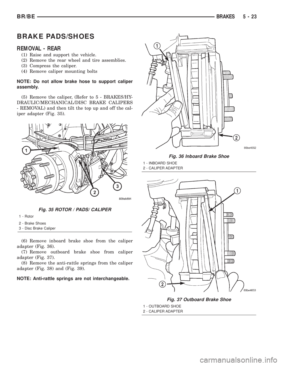
(5) Remove the caliper, (Refer to 5 - BRAKES/HY-
DRAULIC/MECHANICAL/DISC BRAKE CALIPERS
- REMOVAL) and then tilt the top up and off the cal-
iper adapter (Fig. 35).
(6) Remove inboard brake shoe from the caliper
adapter (Fig. 36).
(7) Remove outboard brake shoe from caliper
adapter (Fig. 37).
(8) Remove the anti-rattle springs from the caliper
adapter (Fig. 38) and (Fig. 39).
NOTE: Anti-rattle springs are not interchangeable.
Fig. 35 ROTOR / PADS/ CALIPER
1 - Rotor
2 - Brake Shoes
3 - Disc Brake Caliper
Fig. 36 Inboard Brake Shoe
1 - INBOARD SHOE
2 - CALIPER ADAPTER
Fig. 37 Outboard Brake Shoe
1 - OUTBOARD SHOE
2 - CALIPER ADAPTER
BR/BEBRAKES 5 - 23
Page 297 of 2889
(7) Remove adjuster cable. Slide cable eye off
anchor pin. Then unhook and remove cable from
adjuster lever.
(8) Remove cable guide from secondary shoe and
anchor plate from anchor pin.
(9) Remove adjuster lever. Disengage lever from
spring by sliding lever forward to clear pivot and
work lever out from under spring.
(10) Remove adjuster lever spring from pivot.
(11) Disengage and remove shoe to shoe spring
from brake shoes.
(12) Disengage and remove adjuster screw assem-
bly from brake shoes.
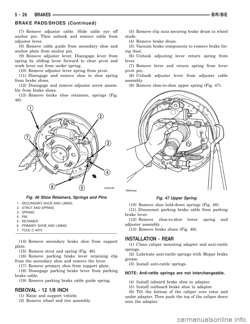
(13) Remove brake shoe retainers, springs (Fig.
46).
(14) Remove secondary brake shoe from support
plate.
(15) Remove strut and spring (Fig. 46).
(16) Remove parking brake lever retaining clip
from the secondary shoe and remove the lever.
(17) Remove primary shoe from support plate.
(18) Disengage parking brake lever from parking
brake cable.
(19) Remove parking brake cable guide spring.
REMOVAL - 12 1/8 INCH
(1) Raise and support vehicle.
(2) Remove wheel and tire assembly.(3) Remove clip nuts securing brake drum to wheel
studs.
(4) Remove brake drum.
(5) Vacuum brake components to remove brake lin-
ing dust.
(6) Unhook adjusting lever return spring from
lever.
(7) Remove lever and return spring from lever
pivot pin.
(8) Unhook adjuster lever from adjuster cable
assembly.
(9) Remove shoe-to-shoe upper spring (Fig. 47).
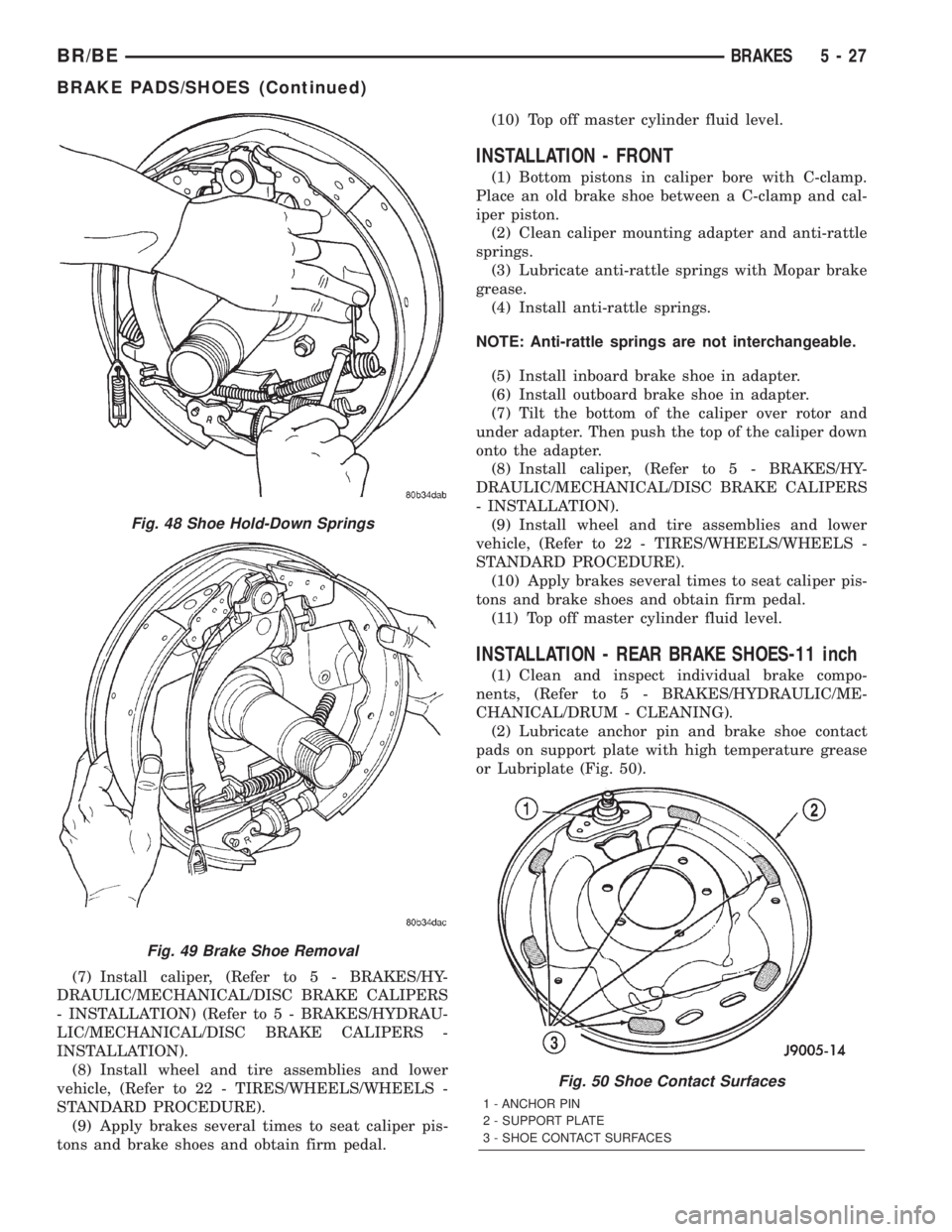
(10) Remove shoe hold-down springs (Fig. 48).
(11) Disconnect parking brake cable from parking
brake lever.
(12) Remove shoe-to-shoe lower spring and
adjuster assembly .
(13) Remove brake shoes (Fig. 49).
INSTALLATION - REAR
(1) Clean caliper mounting adapter and anti-rattle
springs.
(2) Lubricate anti-rattle springs with Mopar brake
grease.
(3) Install anti-rattle springs.
NOTE: Anti-rattle springs are not interchangeable.
(4) Install inboard brake shoe in adapter.
(5) Install outboard brake shoe in adapter.
(6) Tilt the bottom of the caliper over rotor and
under adapter. Then push the top of the caliper down
onto the adapter.
Fig. 46 Shoe Retainers, Springs and Pins
1 - SECONDARY SHOE AND LINING
2 - STRUT AND SPRING
3 - SPRING
4 - PIN
5 - RETAINER
6 - PRIMARY SHOE AND LINING
7 - TOOL C-4070
Fig. 47 Upper Spring
5 - 26 BRAKESBR/BE
BRAKE PADS/SHOES (Continued)
Page 298 of 2889
(7) Install caliper, (Refer to 5 - BRAKES/HY-
DRAULIC/MECHANICAL/DISC BRAKE CALIPERS
- INSTALLATION) (Refer to 5 - BRAKES/HYDRAU-
LIC/MECHANICAL/DISC BRAKE CALIPERS -
INSTALLATION).
(8) Install wheel and tire assemblies and lower
vehicle, (Refer to 22 - TIRES/WHEELS/WHEELS -
STANDARD PROCEDURE).
(9) Apply brakes several times to seat caliper pis-
tons and brake shoes and obtain firm pedal.(10) Top off master cylinder fluid level.
INSTALLATION - FRONT
(1) Bottom pistons in caliper bore with C-clamp.
Place an old brake shoe between a C-clamp and cal-
iper piston.
(2) Clean caliper mounting adapter and anti-rattle
springs.
(3) Lubricate anti-rattle springs with Mopar brake
grease.
(4) Install anti-rattle springs.
NOTE: Anti-rattle springs are not interchangeable.
(5) Install inboard brake shoe in adapter.
(6) Install outboard brake shoe in adapter.
(7) Tilt the bottom of the caliper over rotor and
under adapter. Then push the top of the caliper down
onto the adapter.
(8) Install caliper, (Refer to 5 - BRAKES/HY-
DRAULIC/MECHANICAL/DISC BRAKE CALIPERS
- INSTALLATION).
(9) Install wheel and tire assemblies and lower
vehicle, (Refer to 22 - TIRES/WHEELS/WHEELS -
STANDARD PROCEDURE).
(10) Apply brakes several times to seat caliper pis-
tons and brake shoes and obtain firm pedal.
(11) Top off master cylinder fluid level.
INSTALLATION - REAR BRAKE SHOES-11 inch
(1) Clean and inspect individual brake compo-
nents, (Refer to 5 - BRAKES/HYDRAULIC/ME-
CHANICAL/DRUM - CLEANING).
(2) Lubricate anchor pin and brake shoe contact
pads on support plate with high temperature grease
or Lubriplate (Fig. 50).
Fig. 48 Shoe Hold-Down Springs
Fig. 49 Brake Shoe Removal
Fig. 50 Shoe Contact Surfaces
1 - ANCHOR PIN
2 - SUPPORT PLATE
3 - SHOE CONTACT SURFACES
BR/BEBRAKES 5 - 27
BRAKE PADS/SHOES (Continued)
Page 306 of 2889
ADJUSTMENT WITH ADJUSTING TOOL
(1) Be sure parking brake lever is fully released.
(2) Raise vehicle so rear wheels can be rotated
freely.
(3) Remove plug from each access hole in brake
support plates.
(4) Loosen parking brake cable adjustment nut
until there is slack in front cable.
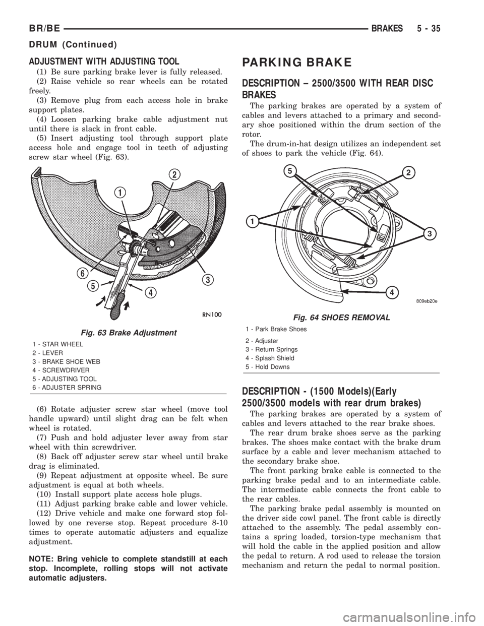
(5) Insert adjusting tool through support plate
access hole and engage tool in teeth of adjusting
screw star wheel (Fig. 63).
(6) Rotate adjuster screw star wheel (move tool
handle upward) until slight drag can be felt when
wheel is rotated.
(7) Push and hold adjuster lever away from star
wheel with thin screwdriver.
(8) Back off adjuster screw star wheel until brake
drag is eliminated.
(9) Repeat adjustment at opposite wheel. Be sure
adjustment is equal at both wheels.
(10) Install support plate access hole plugs.
(11) Adjust parking brake cable and lower vehicle.
(12) Drive vehicle and make one forward stop fol-
lowed by one reverse stop. Repeat procedure 8-10
times to operate automatic adjusters and equalize
adjustment.
NOTE: Bring vehicle to complete standstill at each
stop. Incomplete, rolling stops will not activate
automatic adjusters.
PARKING BRAKE
DESCRIPTION ± 2500/3500 WITH REAR DISC
BRAKES
The parking brakes are operated by a system of
cables and levers attached to a primary and second-
ary shoe positioned within the drum section of the
rotor.
The drum-in-hat design utilizes an independent set
of shoes to park the vehicle (Fig. 64).
DESCRIPTION - (1500 Models)(Early
2500/3500 models with rear drum brakes)
The parking brakes are operated by a system of
cables and levers attached to the rear brake shoes.
The rear drum brake shoes serve as the parking
brakes. The shoes make contact with the brake drum
surface by a cable and lever mechanism attached to
the secondary brake shoe.
The front parking brake cable is connected to the
parking brake pedal and to an intermediate cable.
The intermediate cable connects the front cable to
the rear cables.
The parking brake pedal assembly is mounted on
the driver side cowl panel. The front cable is directly
attached to the assembly. The pedal assembly con-
tains a spring loaded, torsion-type mechanism that
will hold the cable in the applied position and allow
the pedal to return. A rod used to release the torsion
mechanism and return the pedal to normal position.
Fig. 63 Brake Adjustment
1 - STAR WHEEL
2 - LEVER
3 - BRAKE SHOE WEB
4 - SCREWDRIVER
5 - ADJUSTING TOOL
6 - ADJUSTER SPRING
Fig. 64 SHOES REMOVAL
1 - Park Brake Shoes
2 - Adjuster
3 - Return Springs
4 - Splash Shield
5 - Hold Downs
BR/BEBRAKES 5 - 35
DRUM (Continued)
Page 307 of 2889
OPERATION - 2500/3500 WITH REAR DISC
BRAKES
To apply the parking brake the pedal is depressed.
This creates tension in the cable which pulls forward
on the park brake lever. The lever pushes the park
brake shoes outward and into contact with the drum
section of the rotor. The contact of shoe to rotor parks
the vehicle.
A torsion locking mechanism is used to hold the
pedal in an applied position. Parking brake release is
accomplished by the hand release.
A parking brake switch is mounted on the parking
brake lever and is actuated by movement of the
lever. The switch, which is in circuit with the red
warning light in the dash, will illuminate the warn-
ing light whenever the parking brake is applied.
Parking brake adjustment is controlled by a cable
tensioner mechanism. The cable tensioner, once
adjusted at the factory, should not need further
adjustment under normal circumstances. Adjustment
may be required if a new tensioner, or cables are
installed, or disconnected.
OPERATION - (1500 models) (Early 2500/3500
models with rear drum brakes)
To apply the parking brakes, the pedal is
depressed. This pulls the rear brake shoe actuating
levers forward. As the actuating lever is pulled for-
ward, the parking brake strut or cam, exerts a linear
force against the primary brake shoe. This action
presses the primary shoe into contact with the drum.
Once the primary shoe contacts the drum, force is
exerted through the strut/cam. This force is trans-
ferred through the strut/cam to the secondary brake
shoe causing it to pivot into the drum as well.
A torsion locking mechanism is used to hold the
pedal in an applied position. Parking brake release is
accomplished by the hand release.
A parking brake switch is mounted on the parking
brake lever and is actuated by movement of the
lever. The switch, which is in circuit with the red
warning light in the dash, will illuminate the warn-
ing light whenever the parking brake is applied.
Parking brake adjustment is controlled by a cable
tensioner mechanism. The cable tensioner, once
adjusted at the factory, should not need further
adjustment under normal circumstances. Adjustment
may be required if a new tensioner, or cables are
installed, or disconnected.
PEDAL
REMOVAL
(1) Release the parking brake.
(2) Raise the vehicle.(3) Loosen the cable tensioner nut at the equalizer
to create slack in the front cable.
(4) Lower the vehicle.
(5) Remove the knee bolster, (Refer to 23 - BODY/
INSTRUMENT PANEL/STEERING COLUMN
OPENING COVER - REMOVAL).
(6) Disconnect the brake lamp wire from the
switch on the pedal assembly.
(7) Roll the carpet back, loosen the front cable
grommet from the floorpan and the cable retainer.
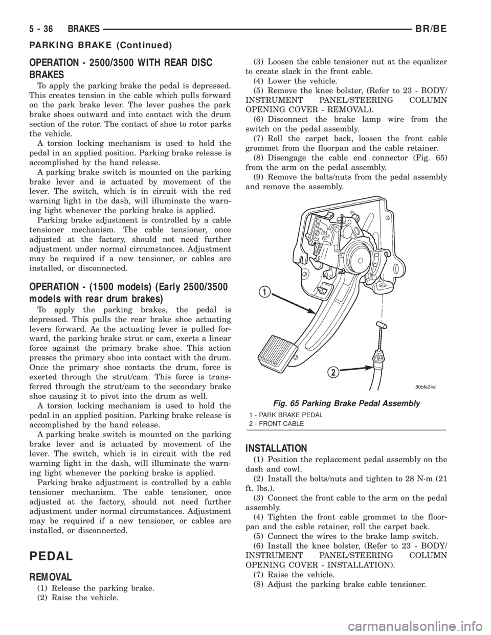
(8) Disengage the cable end connector (Fig. 65)
from the arm on the pedal assembly.
(9) Remove the bolts/nuts from the pedal assembly
and remove the assembly.
INSTALLATION
(1) Position the replacement pedal assembly on the
dash and cowl.
(2) Install the bolts/nuts and tighten to 28 N´m (21
ft. lbs.).
(3) Connect the front cable to the arm on the pedal
assembly.
(4) Tighten the front cable grommet to the floor-
pan and the cable retainer, roll the carpet back.
(5) Connect the wires to the brake lamp switch.
(6) Install the knee bolster, (Refer to 23 - BODY/
INSTRUMENT PANEL/STEERING COLUMN
OPENING COVER - INSTALLATION).
(7) Raise the vehicle.
(8) Adjust the parking brake cable tensioner.
Fig. 65 Parking Brake Pedal Assembly
1 - PARK BRAKE PEDAL
2 - FRONT CABLE
5 - 36 BRAKESBR/BE
PARKING BRAKE (Continued)
Page 308 of 2889
CABLES
REMOVAL - REAR PARK BRAKE CABLE -
2500/3500 WITH REAR DISC BRAKES
(1) Raise and support the vehicle.
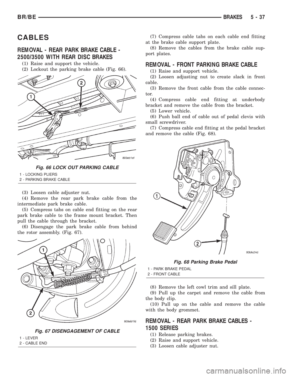
(2) Lockout the parking brake cable (Fig. 66).
(3) Loosen cable adjuster nut.
(4) Remove the rear park brake cable from the
intermediate park brake cable.
(5) Compress tabs on cable end fitting on the rear
park brake cable to the frame mount bracket. Then
pull the cable through the bracket.
(6) Disengage the park brake cable from behind
the rotor assembly. (Fig. 67).(7) Compress cable tabs on each cable end fitting
at the brake cable support plate.
(8) Remove the cables from the brake cable sup-
port plates.REMOVAL - FRONT PARKING BRAKE CABLE
(1) Raise and support vehicle.
(2) Loosen adjusting nut to create slack in front
cable.
(3) Remove the front cable from the cable connec-
tor.
(4) Compress cable end fitting at underbody
bracket and remove the cable from the bracket.
(5) Lower vehicle.
(6) Push ball end of cable out of pedal clevis with
small screwdriver.
(7) Compress cable end fitting at the pedal bracket
and remove the cable (Fig. 68).
(8) Remove the left cowl trim and sill plate.
(9) Pull up the carpet and remove the cable from
the body clip.
(10) Pull up on the cable and remove the cable
with the body grommet.
REMOVAL - REAR PARK BRAKE CABLES -
1500 SERIES
(1) Release parking brakes.
(2) Raise and support vehicle.
(3) Loosen cable adjuster nut.
Fig. 66 LOCK OUT PARKING CABLE
1 - LOCKING PLIERS
2 - PARKING BRAKE CABLE
Fig. 67 DISENGAGEMENT OF CABLE
1 - LEVER
2 - CABLE END
Fig. 68 Parking Brake Pedal
1 - PARK BRAKE PEDAL
2 - FRONT CABLE
BR/BEBRAKES 5 - 37
Page 312 of 2889
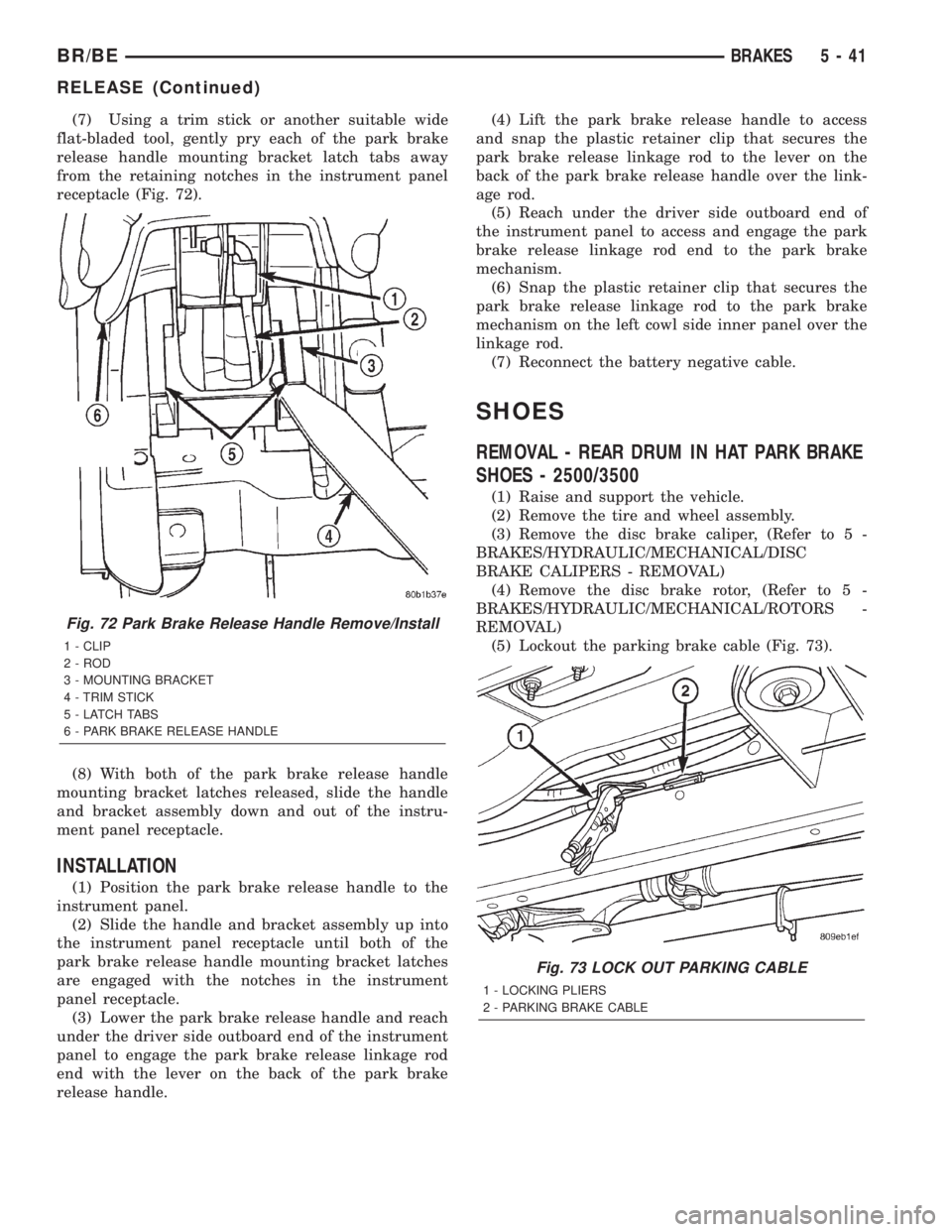
(7) Using a trim stick or another suitable wide
flat-bladed tool, gently pry each of the park brake
release handle mounting bracket latch tabs away
from the retaining notches in the instrument panel
receptacle (Fig. 72).
(8) With both of the park brake release handle
mounting bracket latches released, slide the handle
and bracket assembly down and out of the instru-
ment panel receptacle.
INSTALLATION
(1) Position the park brake release handle to the
instrument panel.
(2) Slide the handle and bracket assembly up into
the instrument panel receptacle until both of the
park brake release handle mounting bracket latches
are engaged with the notches in the instrument
panel receptacle.
(3) Lower the park brake release handle and reach
under the driver side outboard end of the instrument
panel to engage the park brake release linkage rod
end with the lever on the back of the park brake
release handle.(4) Lift the park brake release handle to access
and snap the plastic retainer clip that secures the
park brake release linkage rod to the lever on the
back of the park brake release handle over the link-
age rod.
(5) Reach under the driver side outboard end of
the instrument panel to access and engage the park
brake release linkage rod end to the park brake
mechanism.
(6) Snap the plastic retainer clip that secures the
park brake release linkage rod to the park brake
mechanism on the left cowl side inner panel over the
linkage rod.
(7) Reconnect the battery negative cable.
SHOES
REMOVAL - REAR DRUM IN HAT PARK BRAKE
SHOES - 2500/3500
(1) Raise and support the vehicle.
(2) Remove the tire and wheel assembly.
(3) Remove the disc brake caliper, (Refer to 5 -
BRAKES/HYDRAULIC/MECHANICAL/DISC
BRAKE CALIPERS - REMOVAL)
(4) Remove the disc brake rotor, (Refer to 5 -
BRAKES/HYDRAULIC/MECHANICAL/ROTORS -
REMOVAL)
(5) Lockout the parking brake cable (Fig. 73).
Fig. 72 Park Brake Release Handle Remove/Install
1 - CLIP
2 - ROD
3 - MOUNTING BRACKET
4 - TRIM STICK
5 - LATCH TABS
6 - PARK BRAKE RELEASE HANDLE
Fig. 73 LOCK OUT PARKING CABLE
1 - LOCKING PLIERS
2 - PARKING BRAKE CABLE
BR/BEBRAKES 5 - 41
RELEASE (Continued)
Page 313 of 2889
(6) Disengage the park brake cable from behind
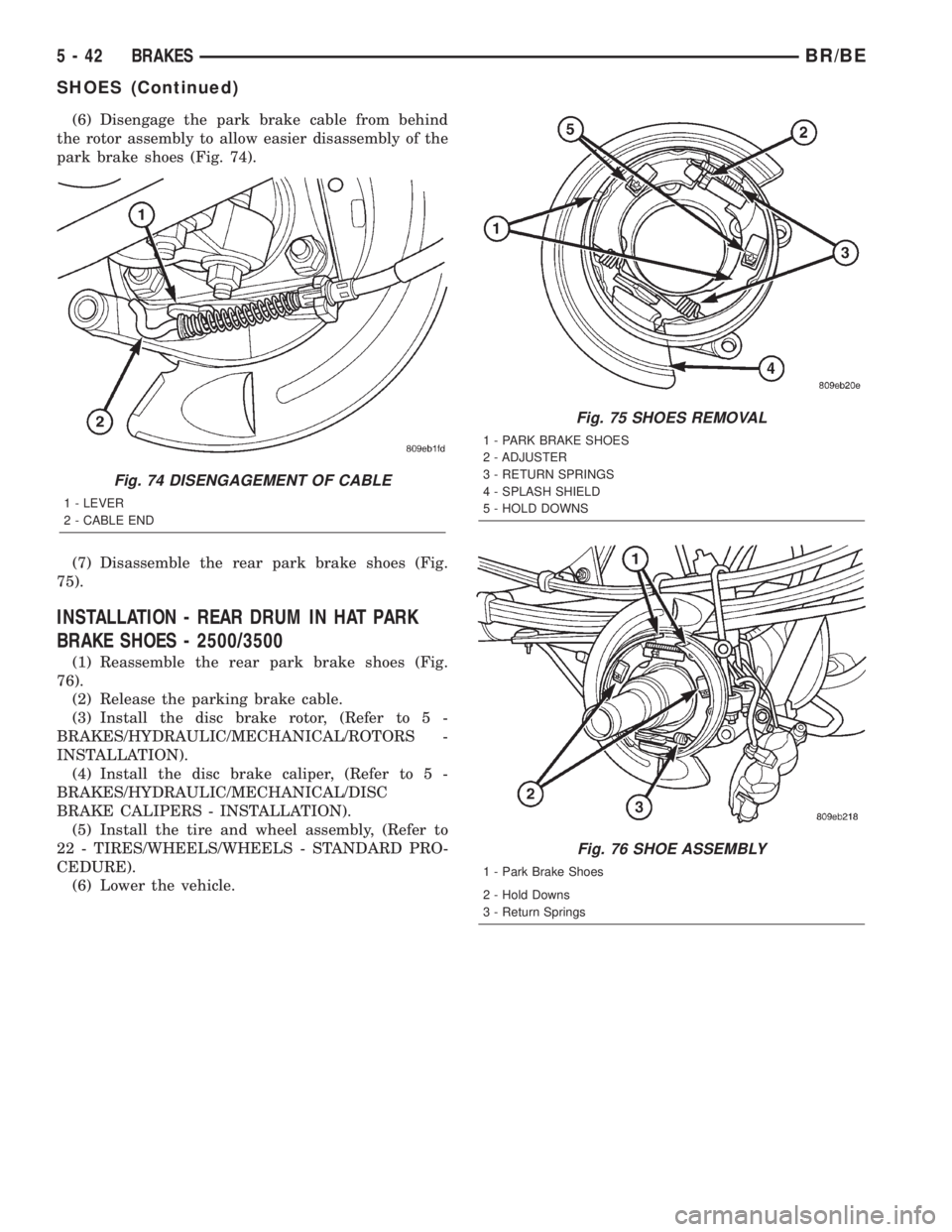
the rotor assembly to allow easier disassembly of the
park brake shoes (Fig. 74).
(7) Disassemble the rear park brake shoes (Fig.
75).
INSTALLATION - REAR DRUM IN HAT PARK
BRAKE SHOES - 2500/3500
(1) Reassemble the rear park brake shoes (Fig.
76).
(2) Release the parking brake cable.
(3) Install the disc brake rotor, (Refer to 5 -
BRAKES/HYDRAULIC/MECHANICAL/ROTORS -
INSTALLATION).
(4) Install the disc brake caliper, (Refer to 5 -
BRAKES/HYDRAULIC/MECHANICAL/DISC
BRAKE CALIPERS - INSTALLATION).
(5) Install the tire and wheel assembly, (Refer to
22 - TIRES/WHEELS/WHEELS - STANDARD PRO-
CEDURE).
(6) Lower the vehicle.
Fig. 74 DISENGAGEMENT OF CABLE
1 - LEVER
2 - CABLE END
Fig. 75 SHOES REMOVAL
1 - PARK BRAKE SHOES
2 - ADJUSTER
3 - RETURN SPRINGS
4 - SPLASH SHIELD
5 - HOLD DOWNS
Fig. 76 SHOE ASSEMBLY
1 - Park Brake Shoes
2 - Hold Downs
3 - Return Springs
5 - 42 BRAKESBR/BE
SHOES (Continued)