2001 DODGE RAM brake rotor
[x] Cancel search: brake rotorPage 275 of 2889
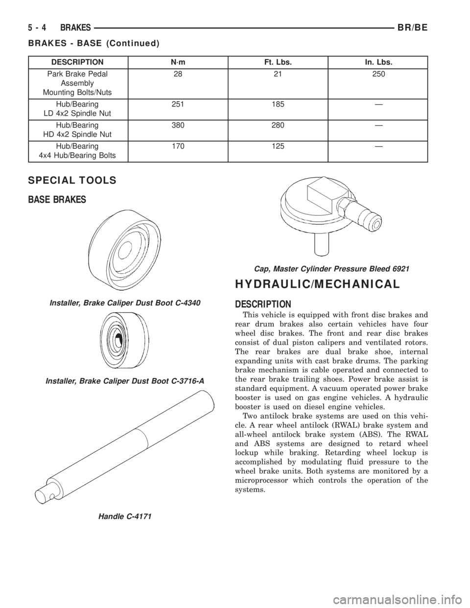
DESCRIPTION N´m Ft. Lbs. In. Lbs.
Park Brake Pedal
Assembly
Mounting Bolts/Nuts28 21 250
Hub/Bearing
LD 4x2 Spindle Nut251 185 Ð
Hub/Bearing
HD 4x2 Spindle Nut380 280 Ð
Hub/Bearing
4x4 Hub/Bearing Bolts170 125 Ð
SPECIAL TOOLS
BASE BRAKES
HYDRAULIC/MECHANICAL
DESCRIPTION
This vehicle is equipped with front disc brakes and
rear drum brakes also certain vehicles have four
wheel disc brakes. The front and rear disc brakes
consist of dual piston calipers and ventilated rotors.
The rear brakes are dual brake shoe, internal
expanding units with cast brake drums. The parking
brake mechanism is cable operated and connected to
the rear brake trailing shoes. Power brake assist is
standard equipment. A vacuum operated power brake
booster is used on gas engine vehicles. A hydraulic
booster is used on diesel engine vehicles.
Two antilock brake systems are used on this vehi-
cle. A rear wheel antilock (RWAL) brake system and
all-wheel antilock brake system (ABS). The RWAL
and ABS systems are designed to retard wheel
lockup while braking. Retarding wheel lockup is
accomplished by modulating fluid pressure to the
wheel brake units. Both systems are monitored by a
microprocessor which controls the operation of the
systems.
Installer, Brake Caliper Dust Boot C-4340
Installer, Brake Caliper Dust Boot C-3716-A
Handle C-4171
Cap, Master Cylinder Pressure Bleed 6921
5 - 4 BRAKESBR/BE
BRAKES - BASE (Continued)
Page 276 of 2889
WARNING
WARNING: DUST AND DIRT ACCUMULATING ON
BRAKE PARTS DURING NORMAL USE MAY CON-
TAIN ASBESTOS FIBERS FROM PRODUCTION OR
AFTERMARKET LININGS. BREATHING EXCESSIVE
CONCENTRATIONS OF ASBESTOS FIBERS CAN
CAUSE SERIOUS BODILY HARM. EXERCISE CARE
WHEN SERVICING BRAKE PARTS. DO NOT CLEAN
BRAKE PARTS WITH COMPRESSED AIR OR BY
DRY BRUSHING. USE A VACUUM CLEANER SPE-
CIFICALLY DESIGNED FOR THE REMOVAL OF
ASBESTOS FIBERS FROM BRAKE COMPONENTS.
IF A SUITABLE VACUUM CLEANER IS NOT AVAIL-
ABLE, CLEANING SHOULD BE DONE WITH A
WATER DAMPENED CLOTH. DO NOT SAND, OR
GRIND BRAKE LINING UNLESS EQUIPMENT USED
IS DESIGNED TO CONTAIN THE DUST RESIDUE.
DISPOSE OF ALL RESIDUE CONTAINING ASBES-
TOS FIBERS IN SEALED BAGS OR CONTAINERS
TO MINIMIZE EXPOSURE TO YOURSELF AND OTH-
ERS. FOLLOW PRACTICES PRESCRIBED BY THE
OCCUPATIONAL SAFETY AND HEALTH ADMINIS-
TRATION AND THE ENVIRONMENTAL PROTECTION
AGENCY FOR THE HANDLING, PROCESSING, AND
DISPOSITION OF DUST OR DEBRIS THAT MAY
CONTAIN ASBESTOS FIBERS.
CAUTION: Never use gasoline, kerosene, alcohol,
motor oil, transmission fluid, or any fluid containing
mineral oil to clean the system components. These
fluids damage rubber cups and seals. Use only
fresh brake fluid or Mopar brake cleaner to clean or
flush brake system components. These are the only
cleaning materials recommended. If system contam-
ination is suspected, check the fluid for dirt, discol-
oration, or separation into distinct layers. Also
check the reservoir cap seal for distortion. Drain
and flush the system with new brake fluid if con-
tamination is suspected.
CAUTION: Use Mopar brake fluid, or an equivalent
quality fluid meeting SAE/DOT standards J1703 and
DOT 3. Brake fluid must be clean and free of con-
taminants. Use fresh fluid from sealed containers
only to ensure proper antilock component opera-
tion.
CAUTION: Use Mopar multi-mileage or high temper-
ature grease to lubricate caliper slide surfaces,
drum brake pivot pins, and shoe contact points on
the backing plates. Use multi-mileage grease or GE
661 or Dow 111 silicone grease on caliper slide pins
to ensure proper operation.
DIAGNOSIS AND TESTING - BASE BRAKE
SYSTEM
Base brake components consist of the brake shoes,
calipers, wheel cylinders, brake drums, rotors, brake
lines, master cylinder, booster, and parking brake
components.
Brake diagnosis involves determining if the prob-
lem is related to a mechanical, hydraulic, or vacuum
operated component.
The first diagnosis step is the preliminary check.
PRELIMINARY BRAKE CHECK
(1) Check condition of tires and wheels. Damaged
wheels and worn, damaged, or underinflated tires
can cause pull, shudder, vibration, and a condition
similar to grab.
(2) If complaint was based on noise when braking,
check suspension components. Jounce front and rear
of vehicle and listen for noise that might be caused
by loose, worn or damaged suspension or steering
components.
(3) Inspect brake fluid level and condition. Note
that the brake reservoir fluid level will decrease in
proportion to normal lining wear.Also note that
brake fluid tends to darken over time. This is
normal and should not be mistaken for contam-
ination.
(a) If fluid level is abnormally low, look for evi-
dence of leaks at calipers, wheel cylinders, brake
lines, and master cylinder.
(b) If fluid appears contaminated, drain out a
sample to examine. System will have to be flushed
if fluid is separated into layers, or contains a sub-
stance other than brake fluid. The system seals
and cups will also have to be replaced after flush-
ing. Use clean brake fluid to flush the system.
(4) Check parking brake operation. Verify free
movement and full release of cables and pedal. Also
note if vehicle was being operated with parking
brake partially applied.
(5) Check brake pedal operation. Verify that pedal
does not bind and has adequate free play. If pedal
lacks free play, check pedal and power booster for
being loose or for bind condition. Do not road test
until condition is corrected.
(6) Check booster vacuum check valve and hose.
(7) If components checked appear OK, road test
the vehicle.
ROAD TESTING
(1) If complaint involved low brake pedal, pump
pedal and note if it comes back up to normal height.
(2) Check brake pedal response with transmission
in Neutral and engine running. Pedal should remain
firm under constant foot pressure.
BR/BEBRAKES 5 - 5
HYDRAULIC/MECHANICAL (Continued)
Page 277 of 2889
(3) During road test, make normal and firm brake
stops in 25-40 mph range. Note faulty brake opera-
tion such as low pedal, hard pedal, fade, pedal pulsa-
tion, pull, grab, drag, noise, etc.
(4) Attempt to stop the vehicle with the parking
brake only and note grab, drag, noise, etc.
PEDAL FALLS AWAY
A brake pedal that falls away under steady foot
pressure is generally the result of a system leak. The
leak point could be at a brake line, fitting, hose, or
caliper/wheel cylinder. If leakage is severe, fluid will
be evident at or around the leaking component.
Internal leakage (seal by-pass) in the master cylin-
der caused by worn or damaged piston cups, may
also be the problem cause.
An internal leak in the ABS or RWAL system may
also be the problem with no physical evidence.
LOW PEDAL
If a low pedal is experienced, pump the pedal sev-
eral times. If the pedal comes back up, worn linings,
rotors, drums, or rear brakes out of adjustment are
the most likely causes. The proper course of action is
to inspect and replace all worn component and make
the proper adjustments.
SPONGY PEDAL
A spongy pedal is most often caused by air in the
system. However, thin brake drums or substandard
brake lines and hoses can also cause a spongy pedal.
The proper course of action is to bleed the system,
and replace thin drums and substandard quality
brake hoses if suspected.
HARD PEDAL OR HIGH PEDAL EFFORT
A hard pedal or high pedal effort may be due to
lining that is water soaked, contaminated, glazed, or
badly worn. The power booster or check valve could
also be faulty.
PEDAL PULSATION
Pedal pulsation is caused by components that are
loose, or beyond tolerance limits.
The primary cause of pulsation are disc brake
rotors with excessive lateral runout or thickness vari-
ation, or out of round brake drums. Other causes are
loose wheel bearings or calipers and worn or dam-
aged tires.
NOTE: Some pedal pulsation may be felt during
ABS/EBD activation.BRAKE DRAG
Brake drag occurs when the lining is in constant
contact with the rotor or drum. Drag can occur at one
wheel, all wheels, fronts only, or rears only.
Drag is a product of incomplete brake shoe release.
Drag can be minor or severe enough to overheat the
linings, rotors and drums.
Minor drag will usually cause slight surface char-
ring of the lining. It can also generate hard spots in
rotors and drums from the overheat-cool down pro-
cess. In most cases, the rotors, drums, wheels and
tires are quite warm to the touch after the vehicle is
stopped.
Severe drag can char the brake lining all the way
through. It can also distort and score rotors and
drums to the point of replacement. The wheels, tires
and brake components will be extremely hot. In
severe cases, the lining may generate smoke as it
chars from overheating.
Common causes of brake drag are:
²Seized or improperly adjusted parking brake
cables
²Loose/worn wheel bearing
²Seized caliper or wheel cylinder piston
²Caliper binding on damaged or missing anti-rat-
tle clips or bushings
²Loose caliper mounting
²Drum brake shoes binding on worn/damaged
support plates
²Mis-assembled components
²Long booster output rod
If brake drag occurs at all wheels, the problem
may be related to a blocked master cylinder return
port, or faulty power booster (binds-does not release).
BRAKE FADE
Brake fade is usually a product of overheating
caused by brake drag. However, brake overheating
and resulting fade can also be caused by riding the
brake pedal, making repeated high deceleration stops
in a short time span, or constant braking on steep
mountain roads. Refer to the Brake Drag information
in this section for causes.
BRAKE PULL
Front brake pull condition could result from:
²Contaminated lining in one caliper
²Seized caliper piston
²Binding caliper
²Loose caliper
²Damaged anti-rattle clips
²Improper brake shoes
²Damaged rotor
A worn, damaged wheel bearing or suspension
component are further causes of pull. A damaged
5 - 6 BRAKESBR/BE
HYDRAULIC/MECHANICAL (Continued)
Page 278 of 2889
front tire (bruised, ply separation) can also cause
pull.
A common and frequently misdiagnosed pull condi-
tion is where direction of pull changes after a few
stops. The cause is a combination of brake drag fol-
lowed by fade at one of the brake units.
As the dragging brake overheats, efficiency is so
reduced that fade occurs. Since the opposite brake
unit is still functioning normally, its braking effect is
magnified. This causes pull to switch direction in
favor of the normally functioning brake unit.
An additional point when diagnosing a change in
pull condition concerns brake cool down. Remember
that pull will return to the original direction, if the
dragging brake unit is allowed to cool down (and is
not seriously damaged).
REAR BRAKE GRAB OR PULL
Rear grab or pull is usually caused by improperly
adjusted or seized parking brake cables, contami-
nated lining, bent or binding shoes and support
plates, or improperly assembled components. This is
particularly true when only one rear wheel is
involved. However, when both rear wheels are
affected, the master cylinder or proportioning valve
could be at fault.
BRAKES DO NOT HOLD AFTER DRIVING THROUGH DEEP
WATER PUDDLES
This condition is generally caused by water soaked
lining. If the lining is only wet, it can be dried by
driving with the brakes very lightly applied for a
mile or two. However, if the lining is both soaked and
dirt contaminated, cleaning and/or replacement will
be necessary.
BRAKE LINING CONTAMINATION
Brake lining contamination is mostly a product of
leaking calipers or wheel cylinders, worn seals, driv-
ing through deep water puddles, or lining that has
become covered with grease and grit during repair.
Contaminated lining should be replaced to avoid fur-
ther brake problems.
WHEEL AND TIRE PROBLEMS
Some conditions attributed to brake components
may actually be caused by a wheel or tire problem.
A damaged wheel can cause shudder, vibration and
pull. A worn or damaged tire can also cause pull.
Severely worn tires with very little tread left can
produce a grab-like condition as the tire loses and
recovers traction. Flat-spotted tires can cause vibra-
tion and generate shudder during brake operation. A
tire with internal damage such as a severe bruise,
cut, or ply separation can cause pull and vibration.BRAKE NOISES
Some brake noise is common with rear drum
brakes and on some disc brakes during the first few
stops after a vehicle has been parked overnight or
stored. This is primarily due to the formation of trace
corrosion (light rust) on metal surfaces. This light
corrosion is typically cleared from the metal surfaces
after a few brake applications causing the noise to
subside.
BRAKE SQUEAK/SQUEAL
Brake squeak or squeal may be due to linings that
are wet or contaminated with brake fluid, grease, or
oil. Glazed linings and rotors with hard spots can
also contribute to squeak. Dirt and foreign material
embedded in the brake lining will also cause squeak/
squeal.
A very loud squeak or squeal is frequently a sign of
severely worn brake lining. If the lining has worn
through to the brake shoes in spots, metal-to-metal
contact occurs. If the condition is allowed to continue,
rotors and drums can become so scored that replace-
ment is necessary.
BRAKE CHATTER
Brake chatter is usually caused by loose or worn
components, or glazed/burnt lining. Rotors with hard
spots can also contribute to chatter. Additional causes
of chatter are out-of-tolerance rotors, brake lining not
securely attached to the shoes, loose wheel bearings
and contaminated brake lining.
THUMP/CLUNK NOISE
Thumping or clunk noises during braking are fre-
quentlynotcaused by brake components. In many
cases, such noises are caused by loose or damaged
steering, suspension, or engine components. However,
calipers that bind on the slide surfaces can generate
a thump or clunk noise. In addition, worn out,
improperly adjusted, or improperly assembled rear
brake shoes can also produce a thump noise.
STANDARD PROCEDURE - MANUAL BLEEDING
Use Mopar brake fluid, or an equivalent quality
fluid meeting SAE J1703-F and DOT 3 standards
only. Use fresh, clean fluid from a sealed container at
all times.
(1) Remove reservoir filler caps and fill reservoir.
(2) If calipers, or wheel cylinders were overhauled,
open all caliper and wheel cylinder bleed screws.
Then close each bleed screw as fluid starts to drip
from it. Top off master cylinder reservoir once more
before proceeding.
(3) Attach one end of bleed hose to bleed screw
and insert opposite end in glass container partially
BR/BEBRAKES 5 - 7
HYDRAULIC/MECHANICAL (Continued)
Page 285 of 2889
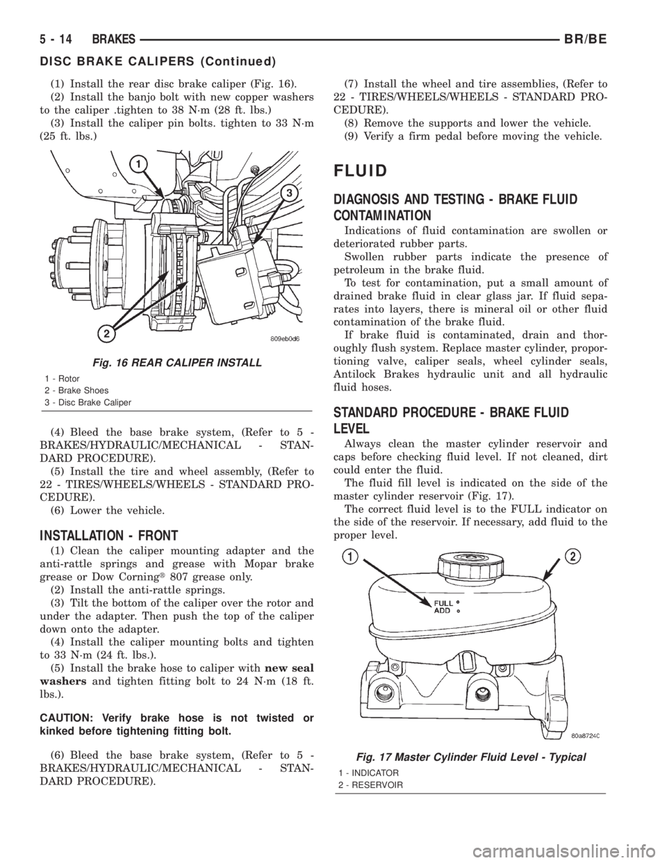
(1) Install the rear disc brake caliper (Fig. 16).
(2) Install the banjo bolt with new copper washers
to the caliper .tighten to 38 N´m (28 ft. lbs.)
(3) Install the caliper pin bolts. tighten to 33 N´m
(25 ft. lbs.)
(4) Bleed the base brake system, (Refer to 5 -
BRAKES/HYDRAULIC/MECHANICAL - STAN-
DARD PROCEDURE).
(5) Install the tire and wheel assembly, (Refer to
22 - TIRES/WHEELS/WHEELS - STANDARD PRO-
CEDURE).
(6) Lower the vehicle.
INSTALLATION - FRONT
(1) Clean the caliper mounting adapter and the
anti-rattle springs and grease with Mopar brake
grease or Dow Corningt807 grease only.
(2) Install the anti-rattle springs.
(3) Tilt the bottom of the caliper over the rotor and
under the adapter. Then push the top of the caliper
down onto the adapter.
(4) Install the caliper mounting bolts and tighten
to 33 N´m (24 ft. lbs.).
(5) Install the brake hose to caliper withnew seal
washersand tighten fitting bolt to 24 N´m (18 ft.
lbs.).
CAUTION: Verify brake hose is not twisted or
kinked before tightening fitting bolt.
(6) Bleed the base brake system, (Refer to 5 -
BRAKES/HYDRAULIC/MECHANICAL - STAN-
DARD PROCEDURE).(7) Install the wheel and tire assemblies, (Refer to
22 - TIRES/WHEELS/WHEELS - STANDARD PRO-
CEDURE).
(8) Remove the supports and lower the vehicle.
(9) Verify a firm pedal before moving the vehicle.
FLUID
DIAGNOSIS AND TESTING - BRAKE FLUID
CONTAMINATION
Indications of fluid contamination are swollen or
deteriorated rubber parts.
Swollen rubber parts indicate the presence of
petroleum in the brake fluid.
To test for contamination, put a small amount of
drained brake fluid in clear glass jar. If fluid sepa-
rates into layers, there is mineral oil or other fluid
contamination of the brake fluid.
If brake fluid is contaminated, drain and thor-
oughly flush system. Replace master cylinder, propor-
tioning valve, caliper seals, wheel cylinder seals,
Antilock Brakes hydraulic unit and all hydraulic
fluid hoses.
STANDARD PROCEDURE - BRAKE FLUID
LEVEL
Always clean the master cylinder reservoir and
caps before checking fluid level. If not cleaned, dirt
could enter the fluid.
The fluid fill level is indicated on the side of the
master cylinder reservoir (Fig. 17).
The correct fluid level is to the FULL indicator on
the side of the reservoir. If necessary, add fluid to the
proper level.
Fig. 16 REAR CALIPER INSTALL
1 - Rotor
2 - Brake Shoes
3 - Disc Brake Caliper
Fig. 17 Master Cylinder Fluid Level - Typical
1 - INDICATOR
2 - RESERVOIR
5 - 14 BRAKESBR/BE
DISC BRAKE CALIPERS (Continued)
Page 291 of 2889
INSTALLATION
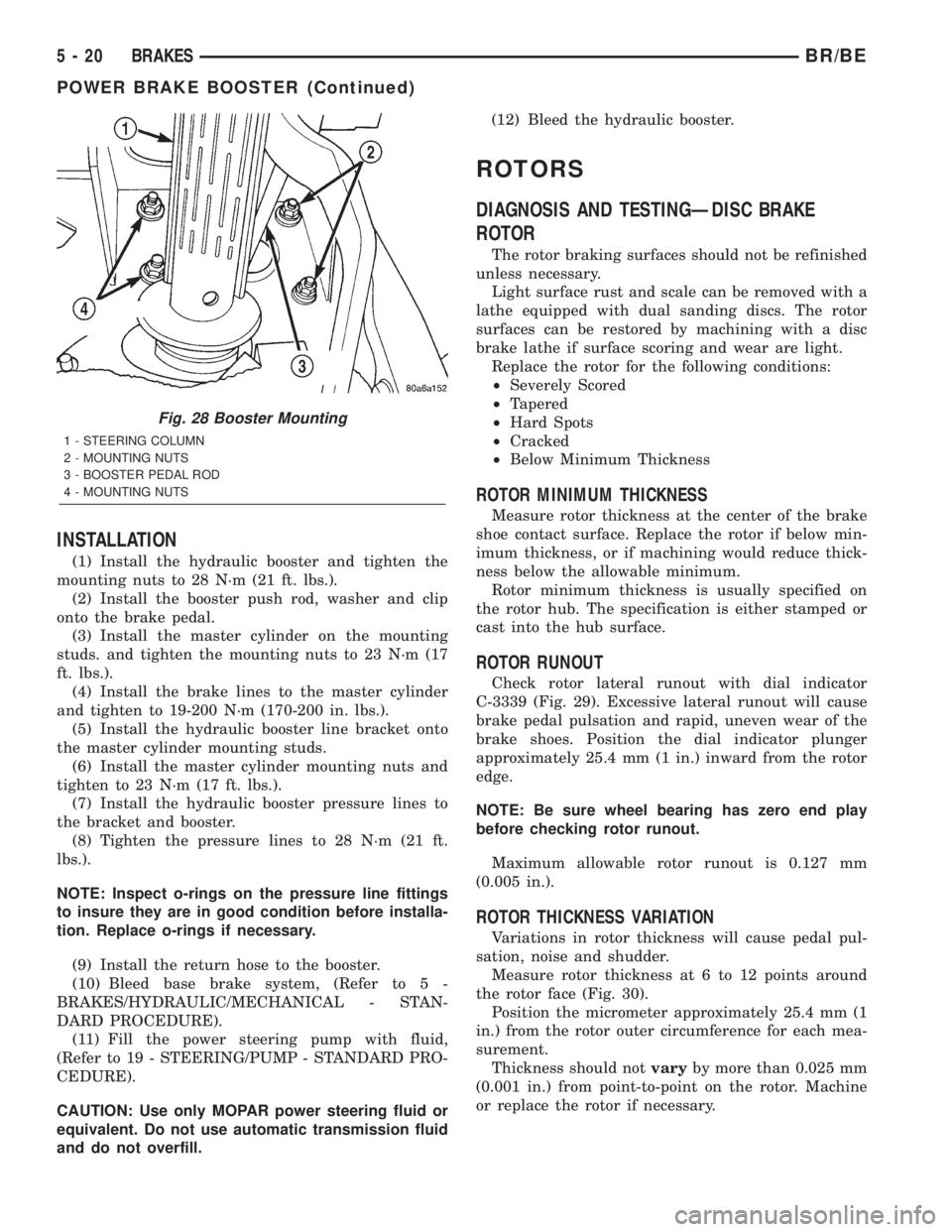
(1) Install the hydraulic booster and tighten the
mounting nuts to 28 N´m (21 ft. lbs.).
(2) Install the booster push rod, washer and clip
onto the brake pedal.
(3) Install the master cylinder on the mounting
studs. and tighten the mounting nuts to 23 N´m (17
ft. lbs.).
(4) Install the brake lines to the master cylinder
and tighten to 19-200 N´m (170-200 in. lbs.).
(5) Install the hydraulic booster line bracket onto
the master cylinder mounting studs.
(6) Install the master cylinder mounting nuts and
tighten to 23 N´m (17 ft. lbs.).
(7) Install the hydraulic booster pressure lines to
the bracket and booster.
(8) Tighten the pressure lines to 28 N´m (21 ft.
lbs.).
NOTE: Inspect o-rings on the pressure line fittings
to insure they are in good condition before installa-
tion. Replace o-rings if necessary.
(9) Install the return hose to the booster.
(10) Bleed base brake system, (Refer to 5 -
BRAKES/HYDRAULIC/MECHANICAL - STAN-
DARD PROCEDURE).
(11) Fill the power steering pump with fluid,
(Refer to 19 - STEERING/PUMP - STANDARD PRO-
CEDURE).
CAUTION: Use only MOPAR power steering fluid or
equivalent. Do not use automatic transmission fluid
and do not overfill.(12) Bleed the hydraulic booster.
ROTORS
DIAGNOSIS AND TESTINGÐDISC BRAKE
ROTOR
The rotor braking surfaces should not be refinished
unless necessary.
Light surface rust and scale can be removed with a
lathe equipped with dual sanding discs. The rotor
surfaces can be restored by machining with a disc
brake lathe if surface scoring and wear are light.
Replace the rotor for the following conditions:
²Severely Scored
²Tapered
²Hard Spots
²Cracked
²Below Minimum Thickness
ROTOR MINIMUM THICKNESS
Measure rotor thickness at the center of the brake
shoe contact surface. Replace the rotor if below min-
imum thickness, or if machining would reduce thick-
ness below the allowable minimum.
Rotor minimum thickness is usually specified on
the rotor hub. The specification is either stamped or
cast into the hub surface.
ROTOR RUNOUT
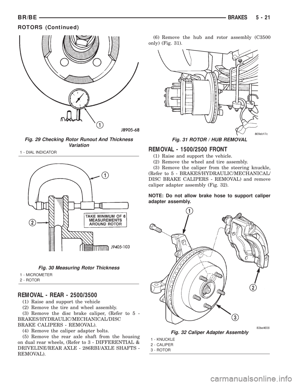
Check rotor lateral runout with dial indicator
C-3339 (Fig. 29). Excessive lateral runout will cause
brake pedal pulsation and rapid, uneven wear of the
brake shoes. Position the dial indicator plunger
approximately 25.4 mm (1 in.) inward from the rotor
edge.
NOTE: Be sure wheel bearing has zero end play
before checking rotor runout.
Maximum allowable rotor runout is 0.127 mm
(0.005 in.).
ROTOR THICKNESS VARIATION
Variations in rotor thickness will cause pedal pul-
sation, noise and shudder.
Measure rotor thickness at 6 to 12 points around
the rotor face (Fig. 30).
Position the micrometer approximately 25.4 mm (1
in.) from the rotor outer circumference for each mea-
surement.
Thickness should notvaryby more than 0.025 mm
(0.001 in.) from point-to-point on the rotor. Machine
or replace the rotor if necessary.
Fig. 28 Booster Mounting
1 - STEERING COLUMN
2 - MOUNTING NUTS
3 - BOOSTER PEDAL ROD
4 - MOUNTING NUTS
5 - 20 BRAKESBR/BE
POWER BRAKE BOOSTER (Continued)
Page 292 of 2889
REMOVAL - REAR - 2500/3500
(1) Raise and support the vehicle
(2) Remove the tire and wheel assembly.
(3) Remove the disc brake caliper, (Refer to 5 -
BRAKES/HYDRAULIC/MECHANICAL/DISC
BRAKE CALIPERS - REMOVAL).
(4) Remove the caliper adapter bolts.
(5) Remove the rear axle shaft from the housing
on dual rear wheels, (Refer to 3 - DIFFERENTIAL &
DRIVELINE/REAR AXLE - 286RBI/AXLE SHAFTS -
REMOVAL).(6) Remove the hub and rotor assembly (C3500
only) (Fig. 31).
REMOVAL - 1500/2500 FRONT
(1) Raise and support the vehicle.
(2) Remove the wheel and tire assembly.
(3) Remove the caliper from the steering knuckle,
(Refer to 5 - BRAKES/HYDRAULIC/MECHANICAL/
DISC BRAKE CALIPERS - REMOVAL) and remove
caliper adapter assembly (Fig. 32).
NOTE: Do not allow brake hose to support caliper
adapter assembly.
Fig. 29 Checking Rotor Runout And Thickness
Variation
1 - DIAL INDICATOR
Fig. 30 Measuring Rotor Thickness
1 - MICROMETER
2 - ROTOR
Fig. 31 ROTOR / HUB REMOVAL
Fig. 32 Caliper Adapter Assembly
1 - KNUCKLE
2 - CALIPER
3 - ROTOR
BR/BEBRAKES 5 - 21
ROTORS (Continued)
Page 293 of 2889
(4) Remove the rotor from the hub/bearing wheel
studs.
REMOVAL - 3500 FRONT
(1) Raise and support the vehicle.
(2) Remove the wheel and tire assembly.
(3) Remove the hub extension mounting nuts and
remove the extension from the rotor if equipped.
(4) Remove the brake caliper adapter assembly.
(Refer to 5 - BRAKES/HYDRAULIC/MECHANICAL/
DISC BRAKE CALIPERS - REMOVAL).
(5) Remove the rotor assembly.
INSTALLATION - REAR - 2500/3500
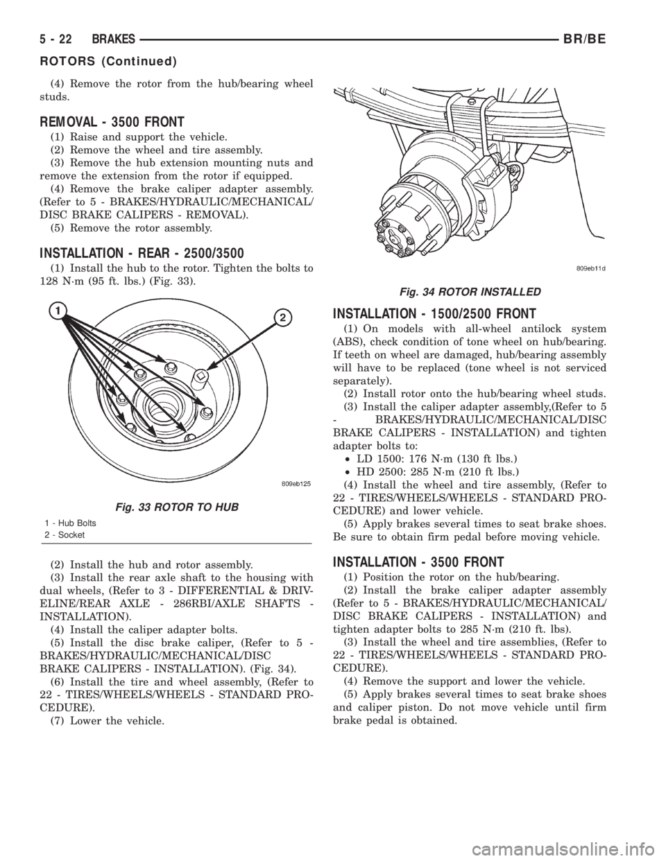
(1) Install the hub to the rotor. Tighten the bolts to
128 N´m (95 ft. lbs.) (Fig. 33).
(2) Install the hub and rotor assembly.
(3) Install the rear axle shaft to the housing with
dual wheels, (Refer to 3 - DIFFERENTIAL & DRIV-
ELINE/REAR AXLE - 286RBI/AXLE SHAFTS -
INSTALLATION).
(4) Install the caliper adapter bolts.
(5) Install the disc brake caliper, (Refer to 5 -
BRAKES/HYDRAULIC/MECHANICAL/DISC
BRAKE CALIPERS - INSTALLATION). (Fig. 34).
(6) Install the tire and wheel assembly, (Refer to
22 - TIRES/WHEELS/WHEELS - STANDARD PRO-
CEDURE).
(7) Lower the vehicle.
INSTALLATION - 1500/2500 FRONT
(1) On models with all-wheel antilock system
(ABS), check condition of tone wheel on hub/bearing.
If teeth on wheel are damaged, hub/bearing assembly
will have to be replaced (tone wheel is not serviced
separately).
(2) Install rotor onto the hub/bearing wheel studs.
(3) Install the caliper adapter assembly,(Refer to 5
- BRAKES/HYDRAULIC/MECHANICAL/DISC
BRAKE CALIPERS - INSTALLATION) and tighten
adapter bolts to:
²LD 1500: 176 N´m (130 ft lbs.)
²HD 2500: 285 N´m (210 ft lbs.)
(4) Install the wheel and tire assembly, (Refer to
22 - TIRES/WHEELS/WHEELS - STANDARD PRO-
CEDURE) and lower vehicle.
(5) Apply brakes several times to seat brake shoes.
Be sure to obtain firm pedal before moving vehicle.
INSTALLATION - 3500 FRONT
(1) Position the rotor on the hub/bearing.
(2) Install the brake caliper adapter assembly
(Refer to 5 - BRAKES/HYDRAULIC/MECHANICAL/
DISC BRAKE CALIPERS - INSTALLATION) and
tighten adapter bolts to 285 N´m (210 ft. lbs).
(3) Install the wheel and tire assemblies, (Refer to
22 - TIRES/WHEELS/WHEELS - STANDARD PRO-
CEDURE).
(4) Remove the support and lower the vehicle.
(5) Apply brakes several times to seat brake shoes
and caliper piston. Do not move vehicle until firm
brake pedal is obtained.
Fig. 33 ROTOR TO HUB
1 - Hub Bolts
2 - Socket
Fig. 34 ROTOR INSTALLED
5 - 22 BRAKESBR/BE
ROTORS (Continued)