2001 DODGE RAM radio
[x] Cancel search: radioPage 522 of 2889
²If both indicator lamps for a heated seat switch
operate, but the heated seat elements do not heat,
refer toHeated Seat Modulein Electronic Control
Modules for the location of the proper heated seat
module diagnosis and testing procedures. Also refer
to the Body Diagnostic Manual for additional diagno-
sis and testing procedures.
²If none of the indicator lamps for both heated
seat switches will operate and the heated seat ele-
ments for both seats do not heat, refer toHeated
Seat Relayin this section for the location of the
proper heated seat relay diagnosis and testing proce-
dures.
²If the an indicator lamp on either heated seat
switch remains illuminated after the heated seat has
been turned Off, refer toHeated Seat Modulein
Electronic Control Modules for the location of the
proper heated seat module diagnosis and testing pro-
cedures. Also refer to the Body Diagnostic Manual for
additional diagnosis and testing procedures.
DRIVER SEAT HEATER
SWITCH
DESCRIPTION
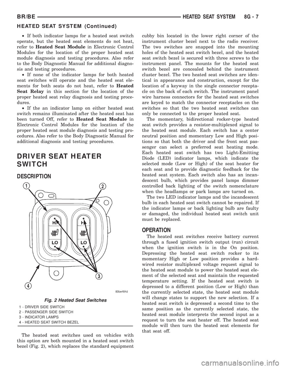
The heated seat switches used on vehicles with
this option are both mounted in a heated seat switch
bezel (Fig. 2), which replaces the standard equipmentcubby bin located in the lower right corner of the
instrument cluster bezel next to the radio receiver.
The two switches are snapped into the mounting
holes of the heated seat switch bezel, and the heated
seat switch bezel is secured with three screws to the
instrument panel. The mounts for the heated seat
switch bezel are concealed behind the instrument
cluster bezel. The two heated seat switches are iden-
tical in appearance and construction, except for the
location of a keyway in the single connector recepta-
cle on the back of each switch. The instrument panel
wire harness connectors for the heated seat switches
are keyed to match the connector receptacles on the
switches so that the two heated seat switches can
only be connected to the proper heated seat.
The momentary, bidirectional rocker-type heated
seat switch provides a resistor-multiplexed signal to
the heated seat module. Each switch has a center
neutral position and momentary Low and High posi-
tions so that both the driver and the front seat pas-
senger can select a preferred seat heating mode.
Each heated seat switch has two Light-Emitting
Diode (LED) indicator lamps, which indicate the
selected mode (Low or High) of the seat heater for
each seat and to provide diagnostic feedback for the
heated seat system. Each switch also has an incan-
descent bulb, which provides panel lamps dimmer
controlled back lighting of the switch nomenclature
when the headlamps or park lamps are turned on.
The two LED indicator lamps and the incandescent
bulb in each heated seat switch cannot be repaired. If
the indicator lamps or back lighting bulb are faulty
or damaged, the individual heated seat switch unit
must be replaced.
OPERATION
The heated seat switches receive battery current
through a fused ignition switch output (run) circuit
when the ignition switch is in the On position.
Depressing the heated seat switch rocker to its
momentary High or Low position provides a hard-
wired resistor multiplexed voltage request signal to
the heated seat module to power the heated seat ele-
ment of the selected seat and maintain the requested
temperature setting. If the heated seat switch is
depressed to a different position (Low or High) than
the currently selected state, the heated seat module
will change states to support the new selection. If a
heated seat switch is depressed a second time to the
same position as the currently selected state, the
heated seat module interprets the second input as a
request to turn the seat heater off. The heated seat
module will then turn the heated seat elements for
that seat off.
Fig. 2 Heated Seat Switches
1 - DRIVER SIDE SWITCH
2 - PASSENGER SIDE SWITCH
3 - INDICATOR LAMPS
4 - HEATED SEAT SWITCH BEZEL
BR/BEHEATED SEAT SYSTEM 8G - 7
HEATED SEAT SYSTEM (Continued)
Page 528 of 2889
(3) The relay normally open terminal (87) is con-
nected to the common feed terminal (30) in the ener-
gized position. This terminal supplies battery voltage
to the heated seat module. There should be continu-
ity between the cavity for relay terminal 87 and the
B(+) to heated seat module circuit cavity of the
heated seat module wire harness connector at all
times. If OK, go to Step 4. If not OK, repair the open
B(+) to heated seat module circuit to the heated seat
module as required.
(4) The coil battery terminal (86) is connected to
the electromagnet in the relay. It is connected to bat-
tery voltage and should be hot at all times. Check for
battery voltage at the cavity for relay terminal 86. If
OK, go to Step 5. If not OK, repair the open circuit to
the fused B(+) fuse in the PDC as required.
(5) The coil ground terminal (85) is connected to
the electromagnet in the relay. It is grounded by the
premium version of the Central Timer Module (CTM)
in response to an engine speed message received over
the Chrysler Collision Detection (CCD) data bus from
the Powertrain Control Module (PCM) when the
engine is running. Check for continuity between the
cavity for relay terminal 85 and the heated seat relay
control circuit cavity of the CTM wire harness con-
nector. There should be continuity at all times. If OK,
use a DRBIIItscan tool and the proper diagnostic
procedures manual to test the operation of the CTM
and CCD data bus. If not OK, repair the open heated
seat relay control circuit as required.
REMOVAL
(1) Disconnect and isolate the battery negative
cable.
(2) Remove the fuse access panel by inserting a
finger in the finger recess molded into the panel and
then pulling the panel sharply away from the left
outboard end of the instrument panel.
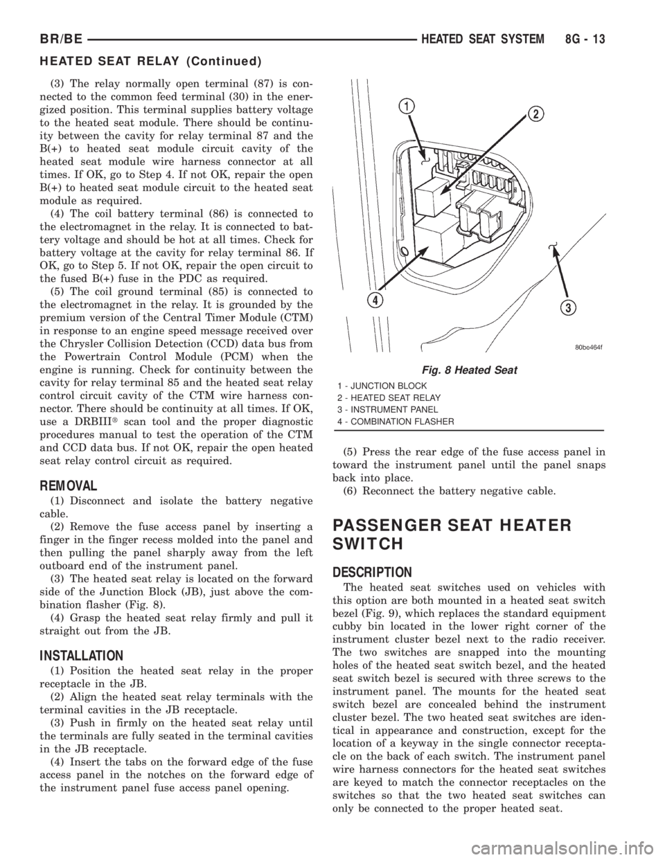
(3) The heated seat relay is located on the forward
side of the Junction Block (JB), just above the com-
bination flasher (Fig. 8).
(4) Grasp the heated seat relay firmly and pull it
straight out from the JB.
INSTALLATION
(1) Position the heated seat relay in the proper
receptacle in the JB.
(2) Align the heated seat relay terminals with the
terminal cavities in the JB receptacle.
(3) Push in firmly on the heated seat relay until
the terminals are fully seated in the terminal cavities
in the JB receptacle.
(4) Insert the tabs on the forward edge of the fuse
access panel in the notches on the forward edge of
the instrument panel fuse access panel opening.(5) Press the rear edge of the fuse access panel in
toward the instrument panel until the panel snaps
back into place.
(6) Reconnect the battery negative cable.
PASSENGER SEAT HEATER
SWITCH
DESCRIPTION
The heated seat switches used on vehicles with
this option are both mounted in a heated seat switch
bezel (Fig. 9), which replaces the standard equipment
cubby bin located in the lower right corner of the
instrument cluster bezel next to the radio receiver.
The two switches are snapped into the mounting
holes of the heated seat switch bezel, and the heated
seat switch bezel is secured with three screws to the
instrument panel. The mounts for the heated seat
switch bezel are concealed behind the instrument
cluster bezel. The two heated seat switches are iden-
tical in appearance and construction, except for the
location of a keyway in the single connector recepta-
cle on the back of each switch. The instrument panel
wire harness connectors for the heated seat switches
are keyed to match the connector receptacles on the
switches so that the two heated seat switches can
only be connected to the proper heated seat.
Fig. 8 Heated Seat
1 - JUNCTION BLOCK
2 - HEATED SEAT RELAY
3 - INSTRUMENT PANEL
4 - COMBINATION FLASHER
BR/BEHEATED SEAT SYSTEM 8G - 13
HEATED SEAT RELAY (Continued)
Page 550 of 2889
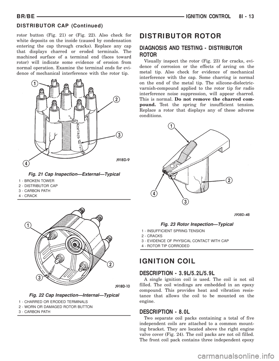
rotor button (Fig. 21) or (Fig. 22). Also check for
white deposits on the inside (caused by condensation
entering the cap through cracks). Replace any cap
that displays charred or eroded terminals. The
machined surface of a terminal end (faces toward
rotor) will indicate some evidence of erosion from
normal operation. Examine the terminal ends for evi-
dence of mechanical interference with the rotor tip.DISTRIBUTOR ROTOR
DIAGNOSIS AND TESTING - DISTRIBUTOR
ROTOR
Visually inspect the rotor (Fig. 23) for cracks, evi-
dence of corrosion or the effects of arcing on the
metal tip. Also check for evidence of mechanical
interference with the cap. Some charring is normal
on the end of the metal tip. The silicone-dielectric-
varnish-compound applied to the rotor tip for radio
interference noise suppression, will appear charred.
This is normal.Do not remove the charred com-
pound.Test the spring for insufficient tension.
Replace a rotor that displays any of these adverse
conditions.
IGNITION COIL
DESCRIPTION - 3.9L/5.2L/5.9L
A single ignition coil is used. The coil is not oil
filled. The coil windings are embedded in an epoxy
compound. This provides heat and vibration resis-
tance that allows the coil to be mounted on the
engine.
DESCRIPTION - 8.0L
Two separate coil packs containing a total of five
independent coils are attached to a common mount-
ing bracket. They are located above the right engine
valve cover (Fig. 24). The coil packs are not oil filled.
The front coil pack contains three independent epoxy
Fig. 21 Cap InspectionÐExternalÐTypical
1 - BROKEN TOWER
2 - DISTRIBUTOR CAP
3 - CARBON PATH
4 - CRACK
Fig. 22 Cap InspectionÐInternalÐTypical
1 - CHARRED OR ERODED TERMINALS
2 - WORN OR DAMAGED ROTOR BUTTON
3 - CARBON PATH
Fig. 23 Rotor InspectionÐTypical
1 - INSUFFICIENT SPRING TENSION
2 - CRACKS
3 - EVIDENCE OF PHYSICAL CONTACT WITH CAP
4 - ROTOR TIP CORRODED
BR/BEIGNITION CONTROL 8I - 13
DISTRIBUTOR CAP (Continued)
Page 556 of 2889
CLEANING
The plugs may be cleaned using commercially
available spark plug cleaning equipment. After clean-
ing, file center electrode flat with a small point file or
jewelers file before adjusting gap.
CAUTION: Never use a motorized wire wheel brush
to clean spark plugs. Metallic deposits will remain
on spark plug insulator and will cause plug misfire.
INSTALLATION
Special care should be taken when installing spark
plugs into the cylinder head spark plug wells. Be
sure the plugs do not drop into the plug wells as elec-
trodes can be damaged.
Always tighten spark plugs to the specified torque.
Over tightening can cause distortion resulting in a
change in the spark plug gap or a cracked porcelain
insulator.
When replacing the spark plug and ignition coil
cables, route the cables correctly and secure them in
the appropriate retainers. Failure to route the cables
properly can cause the radio to reproduce ignition
noise. It could cause cross ignition of the spark plugs
or short circuit the cables to ground.
(1) Start the spark plug into the cylinder head by
hand to avoid cross threading.
(2) Tighten spark plugs to 35-41 N´m (26-30 ft.
lbs.) torque.
(3) Install spark plug cables over spark plugs.
SPARK PLUG CABLE
DESCRIPTION
Spark plug cables are sometimes referred to as sec-
ondary ignition wires.
OPERATION
The spark plug cables transfer electrical current
from the ignition coil(s) and/or distributor, to individ-
ual spark plugs at each cylinder. The resistive spark
plug cables are of nonmetallic construction. The
cables provide suppression of radio frequency emis-
sions from the ignition system.
DIAGNOSIS AND TESTING - SPARK PLUG
CABLES
Cable routing is important on certain engines. To
prevent possible ignition crossfire, be sure the cables
are clipped into the plastic routing looms. Try to pre-
vent any one cable from contacting another. Before
removing cables, note their original location and
routing. Never allow one cable to be twisted around
another.
Check the spark plug cable connections for good
contact at the coil(s), distributor cap towers, and
spark plugs. Terminals should be fully seated. The
insulators should be in good condition and should fit
tightly on the coil, distributor and spark plugs. Spark
plug cables with insulators that are cracked or torn
must be replaced.
Clean high voltage ignition cables with a cloth
moistened with a non-flammable solvent. Wipe the
cables dry. Check for brittle or cracked insulation.
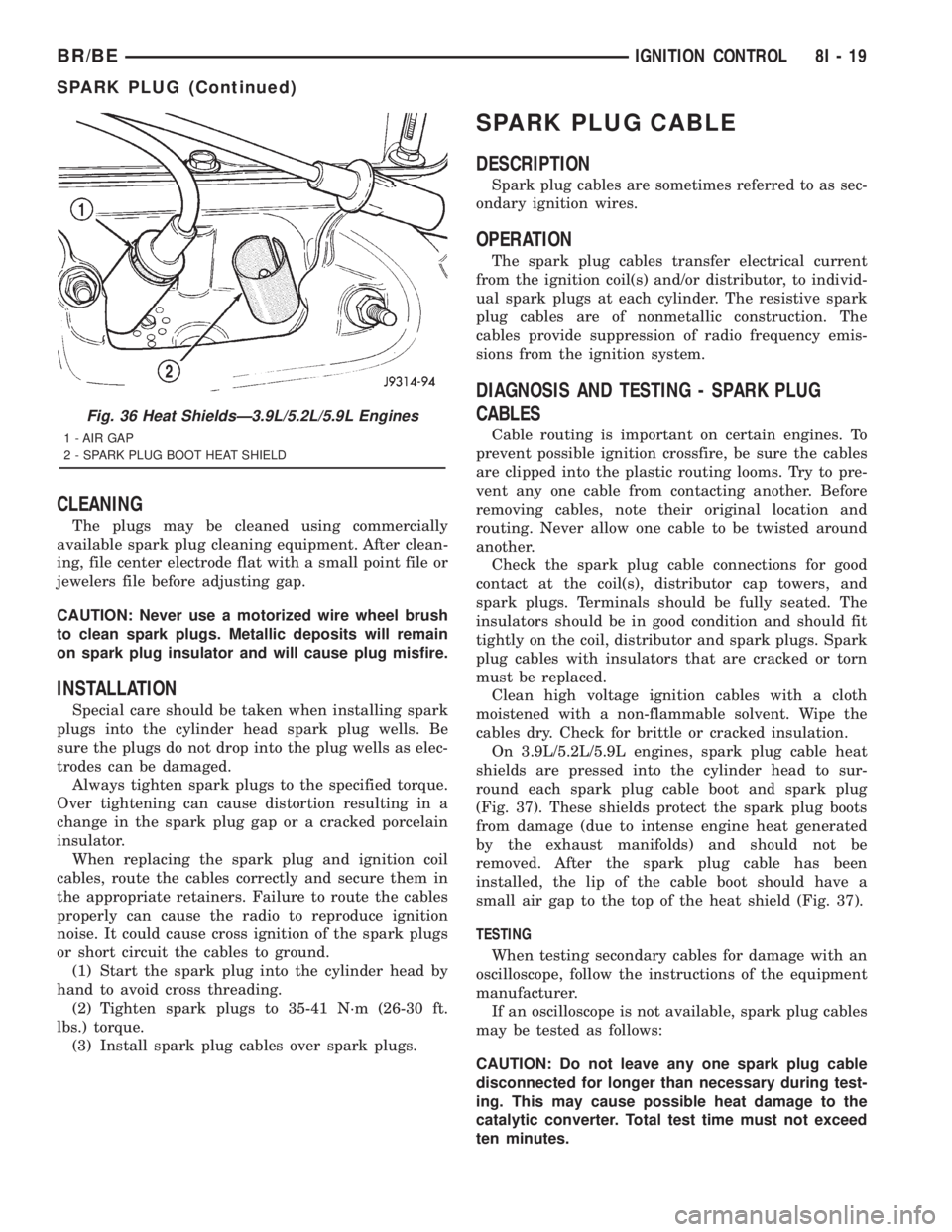
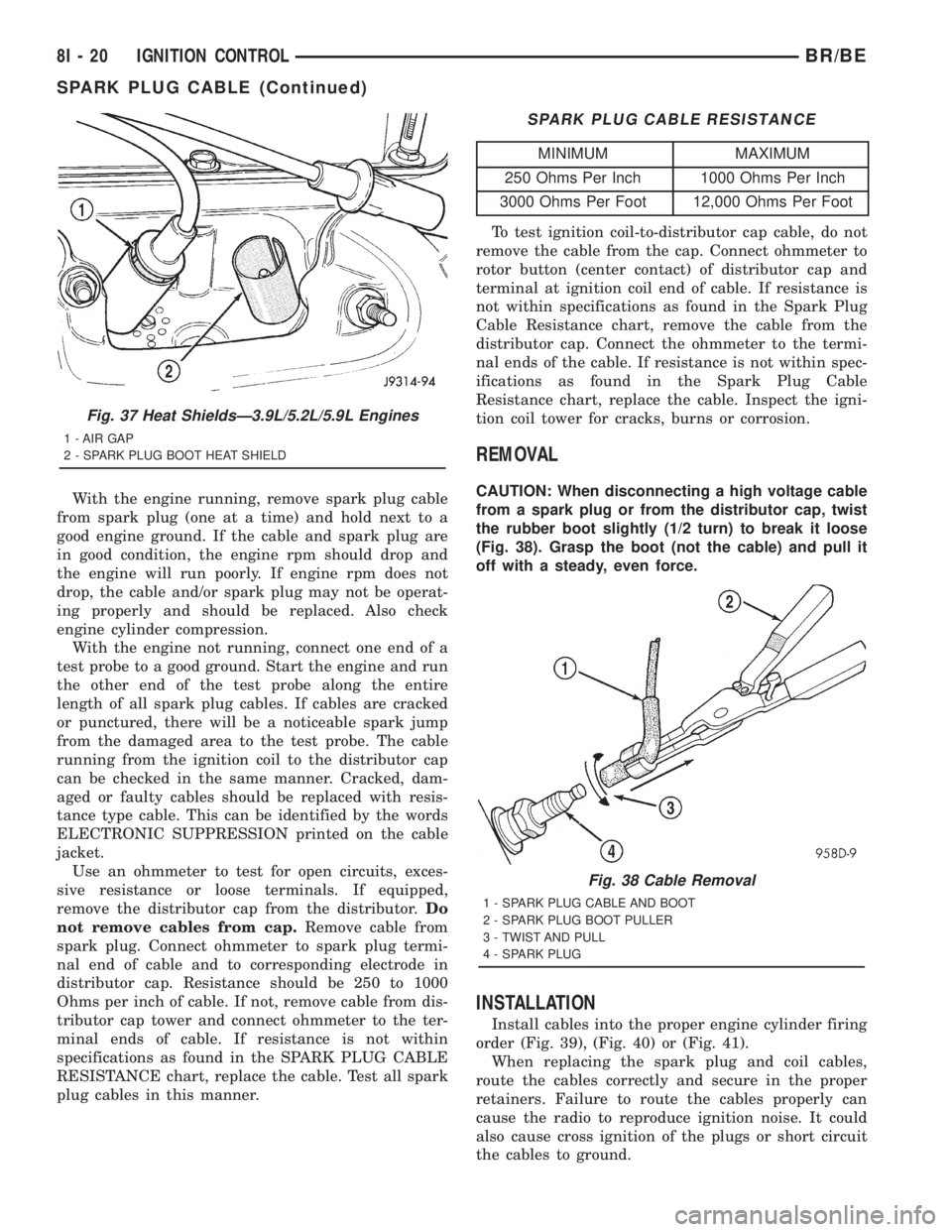
On 3.9L/5.2L/5.9L engines, spark plug cable heat
shields are pressed into the cylinder head to sur-
round each spark plug cable boot and spark plug
(Fig. 37). These shields protect the spark plug boots
from damage (due to intense engine heat generated
by the exhaust manifolds) and should not be
removed. After the spark plug cable has been
installed, the lip of the cable boot should have a
small air gap to the top of the heat shield (Fig. 37).
TESTING
When testing secondary cables for damage with an
oscilloscope, follow the instructions of the equipment
manufacturer.
If an oscilloscope is not available, spark plug cables
may be tested as follows:
CAUTION: Do not leave any one spark plug cable
disconnected for longer than necessary during test-
ing. This may cause possible heat damage to the
catalytic converter. Total test time must not exceed
ten minutes.
Fig. 36 Heat ShieldsÐ3.9L/5.2L/5.9L Engines
1 - AIR GAP
2 - SPARK PLUG BOOT HEAT SHIELD
BR/BEIGNITION CONTROL 8I - 19
SPARK PLUG (Continued)
Page 557 of 2889
With the engine running, remove spark plug cable
from spark plug (one at a time) and hold next to a
good engine ground. If the cable and spark plug are
in good condition, the engine rpm should drop and
the engine will run poorly. If engine rpm does not
drop, the cable and/or spark plug may not be operat-
ing properly and should be replaced. Also check
engine cylinder compression.
With the engine not running, connect one end of a
test probe to a good ground. Start the engine and run
the other end of the test probe along the entire
length of all spark plug cables. If cables are cracked
or punctured, there will be a noticeable spark jump
from the damaged area to the test probe. The cable
running from the ignition coil to the distributor cap
can be checked in the same manner. Cracked, dam-
aged or faulty cables should be replaced with resis-
tance type cable. This can be identified by the words
ELECTRONIC SUPPRESSION printed on the cable
jacket.
Use an ohmmeter to test for open circuits, exces-
sive resistance or loose terminals. If equipped,
remove the distributor cap from the distributor.Do
not remove cables from cap.Remove cable from
spark plug. Connect ohmmeter to spark plug termi-
nal end of cable and to corresponding electrode in
distributor cap. Resistance should be 250 to 1000
Ohms per inch of cable. If not, remove cable from dis-
tributor cap tower and connect ohmmeter to the ter-
minal ends of cable. If resistance is not within
specifications as found in the SPARK PLUG CABLE
RESISTANCE chart, replace the cable. Test all spark
plug cables in this manner.
SPARK PLUG CABLE RESISTANCE
MINIMUM MAXIMUM
250 Ohms Per Inch 1000 Ohms Per Inch
3000 Ohms Per Foot 12,000 Ohms Per Foot
To test ignition coil-to-distributor cap cable, do not
remove the cable from the cap. Connect ohmmeter to
rotor button (center contact) of distributor cap and
terminal at ignition coil end of cable. If resistance is
not within specifications as found in the Spark Plug
Cable Resistance chart, remove the cable from the
distributor cap. Connect the ohmmeter to the termi-
nal ends of the cable. If resistance is not within spec-
ifications as found in the Spark Plug Cable
Resistance chart, replace the cable. Inspect the igni-
tion coil tower for cracks, burns or corrosion.
REMOVAL
CAUTION: When disconnecting a high voltage cable
from a spark plug or from the distributor cap, twist
the rubber boot slightly (1/2 turn) to break it loose
(Fig. 38). Grasp the boot (not the cable) and pull it
off with a steady, even force.
INSTALLATION
Install cables into the proper engine cylinder firing
order (Fig. 39), (Fig. 40) or (Fig. 41).
When replacing the spark plug and coil cables,
route the cables correctly and secure in the proper
retainers. Failure to route the cables properly can
cause the radio to reproduce ignition noise. It could
also cause cross ignition of the plugs or short circuit
the cables to ground.
Fig. 37 Heat ShieldsÐ3.9L/5.2L/5.9L Engines
1 - AIR GAP
2 - SPARK PLUG BOOT HEAT SHIELD
Fig. 38 Cable Removal
1 - SPARK PLUG CABLE AND BOOT
2 - SPARK PLUG BOOT PULLER
3 - TWIST AND PULL
4 - SPARK PLUG
8I - 20 IGNITION CONTROLBR/BE
SPARK PLUG CABLE (Continued)
Page 627 of 2889
(3) Separate lens from lamp.
(4) Grasp bulb, push in slightly and rotate 1/2 turn
counter-clockwise.
PICKUP
(1) Disconnect and isolate the battery negative
cable.
(2) Remove screws from tail lamp.
(3) Grasp lamp, firmly pull lamp rearward to dis-
engage retaining studs.
(4) Remove socket from tail lamp.
(5) Separate tail lamp from cargo box.
(6) Pull bulb from socket.
INSTALLATION
CHASSIS CAB
(1) Install bulb in socket.
(2) Install lamp lens.
(3) Connect the battery negative cable.
PICKUP
(1) Install bulb in socket.
(2) Install socket in tail lamp.
(3) Position tail lamp in cargo box, engage retain-
ing studs and install screws.
(4) Connect the battery negative cable.
TAIL LAMP UNIT
REMOVAL
CAB CHASSIS
(1) Disconnect and isolate the battery negative
cable.
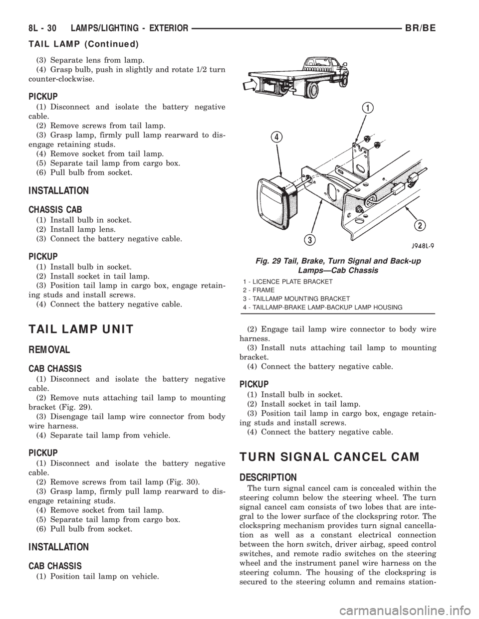
(2) Remove nuts attaching tail lamp to mounting
bracket (Fig. 29).
(3) Disengage tail lamp wire connector from body
wire harness.
(4) Separate tail lamp from vehicle.
PICKUP
(1) Disconnect and isolate the battery negative
cable.
(2) Remove screws from tail lamp (Fig. 30).
(3) Grasp lamp, firmly pull lamp rearward to dis-
engage retaining studs.
(4) Remove socket from tail lamp.
(5) Separate tail lamp from cargo box.
(6) Pull bulb from socket.
INSTALLATION
CAB CHASSIS
(1) Position tail lamp on vehicle.(2) Engage tail lamp wire connector to body wire
harness.
(3) Install nuts attaching tail lamp to mounting
bracket.
(4) Connect the battery negative cable.
PICKUP
(1) Install bulb in socket.
(2) Install socket in tail lamp.
(3) Position tail lamp in cargo box, engage retain-
ing studs and install screws.
(4) Connect the battery negative cable.
TURN SIGNAL CANCEL CAM
DESCRIPTION
The turn signal cancel cam is concealed within the
steering column below the steering wheel. The turn
signal cancel cam consists of two lobes that are inte-
gral to the lower surface of the clockspring rotor. The
clockspring mechanism provides turn signal cancella-
tion as well as a constant electrical connection
between the horn switch, driver airbag, speed control
switches, and remote radio switches on the steering
wheel and the instrument panel wire harness on the
steering column. The housing of the clockspring is
secured to the steering column and remains station-
Fig. 29 Tail, Brake, Turn Signal and Back-up
LampsÐCab Chassis
1 - LICENCE PLATE BRACKET
2 - FRAME
3 - TAILLAMP MOUNTING BRACKET
4 - TAILLAMP-BRAKE LAMP-BACKUP LAMP HOUSING
8L - 30 LAMPS/LIGHTING - EXTERIORBR/BE
TAIL LAMP (Continued)
Page 630 of 2889
LAMPS/LIGHTING - INTERIOR
TABLE OF CONTENTS
page page
LAMPS/LIGHTING - INTERIOR
SPECIFICATIONS........................33
DOME LAMP
REMOVAL..............................33
INSTALLATION...........................33
DOOR AJAR SWITCH
DESCRIPTION...........................34
DIAGNOSIS AND TESTING.................34
DOOR AJAR SWITCH....................34
REMOVAL..............................35
INSTALLATION...........................35GLOVE BOX LAMP AND SWITCH
REMOVAL..............................35
INSTALLATION...........................35
READING LAMP
DESCRIPTION...........................36
OPERATION.............................36
REMOVAL..............................36
INSTALLATION...........................36
VANITY LAMP
REMOVAL..............................37
INSTALLATION...........................37
LAMPS/LIGHTING - INTERIOR
SPECIFICATIONS
INTERIOR LAMPS
LAMP BULB
A/C HEATER CONTROL 158
ASH RECEIVER 161
CIGAR LIGHTER 161
HEADLAMP SWITCH 158
HEATER CONTROL 158
INSTRUMENT CLUSTER PC194
RADIO ASC
AIRBAG HIGH LINE PC194
AIRBAG LOW LINE PC74
ANTI-LOCK BRAKE PC74
BATTERY VOLTAGE PC194
BRAKE WARNING PC194
CHECK ENGINE PC74
ENGINE OIL PRESSURE PC74
FOUR WHEEL DRIVE PC194
HIGH BEAM PC194
LOW FUEL PC194
LOW WASHER FLUID PC74
MAINTENANCE
REQUIREDPC74
MESSAGE CENTER PC194
SEAT BELT PC74
LAMP BULB
TURN SIGNAL PC194
UPSHIFT PC74
DOME 1004
GLOVE COMPARTMENT 1891
VANITY MIRROR LAMP P/N 6501966
DOME LAMP
REMOVAL
(1) Using a small flat blade, pry the left side (driv-
er's side) of the dome lamp lens downward from
dome lamp.
(2) Allow the lens to hang down (Fig. 1) , this will
disengage the right side of the lamp (passenger's
side) from the headliner.
(3) Pull the right side of the lamp down and slide
the lamp to the right (Fig. 2) .
(4) Separate the lamp from the headliner.
(5) Disengage dome lamp wire connector from body
wire harness.
(6) Separate dome lamp from vehicle.
INSTALLATION
(1) Position dome lamp at headliner.
(2) Connect dome lamp wire connector to body
wire harness.
(3) Position the left side of the lamp in the head-
liner opening and slide lamp to the left.
(4) Push the right side of the lamp in the head-
liner opening and push the lamp lens up into the
lamp to secure.
BR/BELAMPS/LIGHTING - INTERIOR 8L - 33
Page 650 of 2889
POWER SYSTEMS
TABLE OF CONTENTS
page page
POWER LOCKS............................ 1
POWER MIRRORS........................ 10POWER SEAT SYSTEM..................... 15
POWER WINDOWS........................ 23
POWER LOCKS
TABLE OF CONTENTS
page page
POWER LOCKS
DESCRIPTION............................1
OPERATION.............................3
DIAGNOSIS AND TESTING..................4
POWER LOCK SYSTEM...................4
POWER LOCK & REMOTE KEYLESS
ENTRY SYSTEM.........................4
DOOR CYLINDER LOCK SWITCH
DESCRIPTION............................5
OPERATION.............................5
DIAGNOSIS AND TESTING..................5
DOOR CYLINDER LOCK SWITCH...........5
REMOVAL...............................6
INSTALLATION............................6
POWER LOCK MOTOR
DESCRIPTION............................6OPERATION.............................6
DIAGNOSIS AND TESTING..................7
POWER LOCK MOTOR...................7
REMOTE KEYLESS ENTRY TRANSMITTER
DESCRIPTION............................7
OPERATION.............................7
DIAGNOSIS AND TESTING..................7
REMOTE KEYLESS ENTRY TRANSMITTER....7
STANDARD PROCEDURE...................8
RKE TRANSMITTER PROGRAMMING........8
RKE TRANSMITTER BATTERIES............8
POWER LOCK SWITCH
DESCRIPTION............................8
OPERATION.............................8
DIAGNOSIS AND TESTING..................8
POWER LOCK SWITCH...................8
POWER LOCKS
DESCRIPTION - POWER LOCK SYSTEM
Two different power lock systems are offered as
optional factory-installed equipment on this model.
Both power lock systems are offered only on models
that are also equipped with power windows. On mod-
els without the optional Remote Keyless Entry (RKE)
system, a base version of the Central Timer Module
(CTM) is used. In this version of the power lock sys-
tem, the power lock switches provide the only control
over the operation of the power lock motors. On mod-
els with the optional RKE system, a high-line or pre-
mium version of the CTM is used to provide many
electronic features and conveniences that are not pos-
sible with the base version CTM. In this power lock
system, the power lock motors are controlled by the
microprocessor-based high-line or premium version ofthe CTM based upon the CTM programming and
electronic message inputs received from other elec-
tronic modules in the vehicle over the Chrysler Col-
lision Detection (CCD) data bus network, Radio
Frequency (RF) inputs received from the RKE trans-
mitters, as well as many hard wired inputs.
Both versions of the power lock system include the
following major components, which are described in
further detail elsewhere in this service manual:
²Power Lock Motors- A reversible electric
motor integral to the door latch of each front door
locks or unlocks the front door latch when provided
with the appropriate electrical inputs.
²Power Lock Switches- A power lock switch
integral to the power window/lock switch unit located
near the forward end of the arm rest on each front
door trim panel allows the power door lock system to
be operated by either the driver or the front seat pas-
senger.
BR/BEPOWER SYSTEMS 8N - 1