2001 DODGE RAM washer fluid
[x] Cancel search: washer fluidPage 400 of 2889
(10) Lift radiator straight up and out of engine
compartment. The bottom of the radiator is equipped
with two alignment dowels that fit into holes in the
lower radiator support panel (Fig. 42). Rubber bis-
cuits (insulators) are installed to these dowels. Take
care not to damage cooling fins or tubes on the radi-
ator and air conditioning condenser when removing.
CLEANING
Clean radiator fins are necessary for good heat
transfer. The radiator and air conditioning fins
should be cleaned when an accumulation of debris
has occurred. With the engine cold, apply cold water
and compressed air to the back (engine side) of the
radiator to flush the radiator and/or A/C condenser of
debris.
INSPECTION
Inspect the radiator side tanks for cracks, broken
or missing fittings also inspect the joint where the
tanks seam up to the radiator core for signs of leak-
age and/or deteriorating seals.
Inspect radiator core for corroded, bent or missing
cooling fins. Inspect the core for bent or damaged
cooling tubes.
INSTALLATION
(1) Position fan shroud over the fan blades rear-
ward towards engine.
(2) Install rubber insulators to alignment dowels
at lower part of radiator.
(3) Lower the radiator into position while guiding
the two alignment dowels into lower radiator sup-
port. Different alignment holes are provided in the
lower radiator support for each engine application.
(4) Install two upper radiator mounting bolts.
Tighten bolts to 11 N´m (95 in. lbs.) torque.
(5) Connect both radiator hoses and install hose
clamps.
(6) Connect transmission cooler lines to radiator
tank. Inspect quick connect fittings for debris and
install until an audible ªclickº is heard. Pull apart to
verify connection.
(7) Install windshield washer reservoir tank.
(8) Position fan shroud to flanges on sides of radi-
ator. Install fan shroud mounting bolts (Fig. 41).
Tighten bolts to 6 N´m (50 in. lbs.) torque.
(9) Install metal clips to top of fan shroud.
(10) Install coolant reserve/overflow tank hose to
radiator filler neck nipple.
(11) Install coolant reserve/overflow tank to fan
shroud (fits into T-slots on shroud).
(12) Install battery negative cables.
(13) Install positive battery cable to top of radia-
tor. Tighten radiator-to-battery cable mounting nuts.
(14) Position heater controls tofull heatposition.(15) Fill cooling system with coolant (Refer to 7 -
COOLING - STANDARD PROCEDURE).
(16) Operate engine until it reaches normal tem-
perature. Check cooling system and automatic trans-
mission (if equipped) fluid levels.
RADIATOR PRESSURE CAP
DESCRIPTION
Radiators are equipped with a pressure cap, which
releases pressure at some point within a range of
97-124 kPa (14-18 psi). The pressure relief point (in
pounds) is engraved on top of cap.
The cooling system will operate at pressures
slightly above atmospheric pressure. This results in a
higher coolant boiling point allowing increased radi-
ator cooling capacity.
A rubber gasket seals radiator filler neck to pre-
vent leakage. This is done to keep system under
pressure. It also maintains vacuum during coolant
cool-down allowing coolant to return from reserve/
overflow tank.
OPERATION
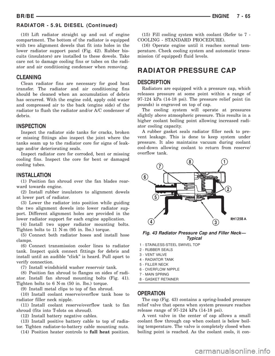
The cap (Fig. 43) contains a spring-loaded pressure
relief valve that opens when system pressure reaches
release range of 97-124 kPa (14-18 psi).
A vent valve in the center of cap allows a small
coolant flow through cap when coolant is below boil-
ing temperature. The valve is completely closed when
boiling point is reached. As the coolant cools, it con-
Fig. 43 Radiator Pressure Cap and Filler NeckÐ
Typical
1 - STAINLESS-STEEL SWIVEL TOP
2 - RUBBER SEALS
3 - VENT VALVE
4 - RADIATOR TANK
5 - FILLER NECK
6 - OVERFLOW NIPPLE
7 - MAIN SPRING
8 - GASKET RETAINER
BR/BEENGINE 7 - 65
RADIATOR - 5.9L DIESEL (Continued)
Page 560 of 2889
INSTRUMENT CLUSTER
TABLE OF CONTENTS
page page
INSTRUMENT CLUSTER
DESCRIPTION............................2
OPERATION.............................3
DIAGNOSIS AND TESTING..................6
INSTRUMENT CLUSTER..................6
REMOVAL..............................10
DISASSEMBLY...........................11
ASSEMBLY.............................13
INSTALLATION...........................14
ABS INDICATOR
DESCRIPTION...........................14
OPERATION.............................14
AIRBAG INDICATOR
DESCRIPTION...........................15
OPERATION.............................15
BRAKE/PARK BRAKE INDICATOR
DESCRIPTION...........................16
OPERATION.............................16
DIAGNOSIS AND TESTING.................16
BRAKE INDICATOR.....................16
CHECK GAUGES INDICATOR
DESCRIPTION...........................17
OPERATION.............................17
CRUISE INDICATOR
DESCRIPTION...........................18
OPERATION.............................18
ENGINE TEMPERATURE GAUGE
DESCRIPTION...........................19
OPERATION.............................19
FUEL GAUGE
DESCRIPTION...........................20
OPERATION.............................20
GEAR SELECTOR INDICATOR
DESCRIPTION...........................21
OPERATION.............................21
HIGH BEAM INDICATOR
DESCRIPTION...........................21
OPERATION.............................22
DIAGNOSIS AND TESTING.................22
HIGH BEAM INDICATOR.................22
LOW FUEL INDICATOR
DESCRIPTION...........................23
OPERATION.............................23
MALFUNCTION INDICATOR LAMP (MIL)
DESCRIPTION...........................24
OPERATION.............................24
ODOMETER
DESCRIPTION...........................24
OPERATION.............................25OIL PRESSURE GAUGE
DESCRIPTION...........................25
OPERATION.............................26
OVERDRIVE OFF INDICATOR
DESCRIPTION...........................27
OPERATION.............................27
SEATBELT INDICATOR
DESCRIPTION...........................27
OPERATION.............................27
SERVICE REMINDER INDICATOR
DESCRIPTION...........................28
OPERATION.............................28
SHIFT INDICATOR (TRANSFER CASE)
DESCRIPTION...........................29
OPERATION.............................29
DIAGNOSIS AND TESTING.................29
FOUR-WHEEL DRIVE INDICATOR..........29
SPEEDOMETER
DESCRIPTION...........................30
OPERATION.............................30
TACHOMETER
DESCRIPTION...........................30
OPERATION.............................31
TRANSMISSION OVERTEMP INDICATOR
DESCRIPTION...........................31
OPERATION.............................31
TURN SIGNAL INDICATORS
DESCRIPTION...........................32
OPERATION.............................32
DIAGNOSIS AND TESTING.................32
TURN SIGNAL INDICATORS..............32
UPSHIFT INDICATOR
DESCRIPTION...........................33
OPERATION.............................33
VOLTAGE GAUGE
DESCRIPTION...........................33
OPERATION.............................34
WAIT-TO-START INDICATOR
DESCRIPTION...........................34
OPERATION.............................35
WASHER FLUID INDICATOR
DESCRIPTION...........................35
OPERATION.............................35
DIAGNOSIS AND TESTING.................36
WASHER FLUID INDICATOR..............36
WATER-IN-FUEL INDICATOR
DESCRIPTION...........................36
OPERATION.............................37
BR/BEINSTRUMENT CLUSTER 8J - 1
Page 562 of 2889
²Check Gauges Indicator
²Cruise Indicator (Odometer VFD)
²Four-Wheel Drive Indicator
²High Beam Indicator
²Low Fuel Indicator
²Washer Fluid Indicator
²Malfunction Indicator Lamp (MIL)
²Overdrive-Off Indicator
²Seatbelt Indicator
²Service Reminder Indicator (SRI)
²Transmission Overtemp Indicator
²Turn Signal (Right and Left) Indicators
²Upshift Indicator
²Wait-To-Start Indicator (Diesel Only)
²Water-In-Fuel Indicator (Diesel Only)
Some of these indicators are either programmable
or automatically configured when the EMIC is con-
nected to the vehicle electrical system. This feature
allows those indicators to be activated or deactivated
for compatibility with certain optional equipment.
The EMIC also includes a provision for mounting the
automatic transmission gear selector indicator in the
lower right corner of the cluster. The spring-loaded,
cable driven, mechanical gear selector indicator gives
an indication of the transmission gear that has been
selected with the automatic transmission gear selec-
tor lever. The gear selector indicator pointer is easily
visible through an opening provided in the front of
the cluster overlay, and is also lighted by the cluster
illumination lamps for visibility at night. Models
equipped with a manual transmission have a block-
out plate installed in place of the gear selector indi-
cator.
Cluster illumination is accomplished by adjustable
incandescent back lighting, which illuminates the
gauges for visibility when the exterior lighting is
turned on. The EMIC high beam indicator, turn sig-
nal indicators, and wait-to-start indicator are also
illuminated by dedicated incandescent bulbs. The
remaining indicators in the EMIC are each illumi-
nated by a dedicated Light Emitting Diode (LED)
that is soldered onto the electronic circuit board.
Each of the incandescent bulbs is secured by an inte-
gral bulb holder to the electronic circuit board from
the back of the cluster housing.
Hard wired circuitry connects the EMIC to the
electrical system of the vehicle. These hard wired cir-
cuits are integral to several wire harnesses, which
are routed throughout the vehicle and retained by
many different methods. These circuits may be con-
nected to each other, to the vehicle electrical system
and to the EMIC through the use of a combination of
soldered splices, splice block connectors, and many
different types of wire harness terminal connectors
and insulators. Refer to the appropriate wiring infor-
mation. The wiring information includes wiring dia-grams, proper wire and connector repair procedures,
further details on wire harness routing and reten-
tion, as well as pin-out and location views for the
various wire harness connectors, splices and grounds.
The EMIC modules for this model are serviced only
as complete units. The EMIC module cannot be
adjusted or repaired. If a gauge, an LED indicator,
the VFD, the electronic circuit board, the circuit
board hardware, the cluster overlay, or the EMIC
housing are damaged or faulty, the entire EMIC mod-
ule must be replaced. The cluster lens and hood unit,
the rear cluster housing cover, the automatic trans-
mission gear selector indicator, and the incandescent
lamp bulbs with holders are available for individual
service replacement.
OPERATION
The ElectroMechanical Instrument Cluster (EMIC)
is designed to allow the vehicle operator to monitor
the conditions of many of the vehicle components and
operating systems. The gauges and indicators in the
EMIC provide valuable information about the various
standard and optional powertrains, fuel and emis-
sions systems, cooling systems, lighting systems,
safety systems and many other convenience items.
The EMIC is installed in the instrument panel so
that all of these monitors can be easily viewed by the
vehicle operator when driving, while still allowing
relative ease of access for service. The microproces-
sor-based EMIC hardware and software uses various
inputs to control the gauges and indicators visible on
the face of the cluster. Some of these inputs are hard
wired, but most are in the form of electronic mes-
sages that are transmitted by other electronic mod-
ules over the Chrysler Collision Detection (CCD) data
bus network. (Refer to 8 - ELECTRICAL/ELEC-
TRONIC CONTROL MODULES/COMMUNICATION
- OPERATION).
The EMIC microprocessor smooths the input data
using algorithms to provide gauge readings that are
accurate, stable and responsive to operating condi-
tions. These algorithms are designed to provide
gauge readings during normal operation that are con-
sistent with customer expectations. However, when
abnormal conditions exist, such as low/high battery
voltage, low oil pressure, or high coolant tempera-
ture, the algorithm drives the gauge pointer to an
extreme position and the microprocessor turns on the
Check Gauges indicator to provide a distinct visual
indication of a problem to the vehicle operator. The
instrument cluster circuitry may also generate a
hard wired chime tone request to the Central Timer
Module (CTM) when it monitors certain conditions or
inputs, in order to provide the vehicle operator with
an audible alert.
BR/BEINSTRUMENT CLUSTER 8J - 3
INSTRUMENT CLUSTER (Continued)
Page 564 of 2889
The VFD is diagnosed using the EMIC self-diag-
nostic actuator test. (Refer to 8 - ELECTRICAL/IN-
STRUMENT CLUSTER - DIAGNOSIS AND
TESTING). Proper testing of the CCD data bus and
the data bus message inputs to the EMIC that con-
trol some of the VFD functions requires the use of a
DRBIIItscan tool. Refer to the appropriate diagnos-
tic information. Specific operation details for the
odometer and trip odometer functions of the VFD
may be found elsewhere in this service manual.
INDICATORS
Indicators are located in various positions within
the EMIC and are all connected to the EMIC circuit
board. The four-wheel drive indicator, high beam
indicator, washer fluid indicator, turn signal indica-
tors, and wait-to-start indicator are hard wired. The
brake indicator is controlled by CCD data bus mes-
sages from the Controller Anti-lock Brake (CAB) and
the hard wired park brake switch input to the EMIC.
The seatbelt indicator is controlled by the EMIC pro-
gramming, CCD data bus messages from the Airbag
Control Module (ACM), and the hard wired seat belt
switch input to the EMIC. The Malfunction Indicator
Lamp (MIL) is normally controlled by CCD data bus
messages from the Powertrain Control Module
(PCM); however, if the EMIC loses CCD data bus
communications, the EMIC circuitry will automati-
cally turn the MIL on, and flash the odometer VFD
on and off repeatedly until CCD data bus communi-
cation is restored. The EMIC uses CCD data bus
messages from the Powertrain Control Module
(PCM), the diesel engine only Engine Control Module
(ECM), the ACM, and the CAB to control all of the
remaining indicators. Different indicators are con-
trolled by different strategies; some receive fused
ignition switch output from the EMIC circuitry clus-
ter and have a switched ground, while others are
grounded through the EMIC circuitry and have a
switched battery feed.
In addition, certain indicators in this instrument
cluster are programmable or configurable. This fea-
ture allows the programmable indicators to be acti-
vated or deactivated with a DRBIIItscan tool, while
the configurable indicators will be automatically
enabled or disabled by the EMIC circuitry for com-
patibility with certain optional equipment. The only
programmable indicator for this model is the upshift
indicator. The cruise indicator, four-wheel drive indi-
cator, overdrive-off indicator, service reminder indica-
tor, and the transmission overtemp indicator are
automatically configured, either electronically or
mechanically.The hard wired indicators are diagnosed using con-
ventional diagnostic methods. The EMIC and CCD
bus message controlled indicator lamps are diagnosed
using the EMIC self-diagnostic actuator test. (Refer
to 8 - ELECTRICAL/INSTRUMENT CLUSTER -
DIAGNOSIS AND TESTING). Proper testing of the
CCD data bus and the data bus message inputs to
the EMIC that control each indicator lamp require
the use of a DRBIIItscan tool. Refer to the appro-
priate diagnostic information. Specific operation
details for each indicator may be found elsewhere in
this service manual.
CLUSTER ILLUMINATION
The EMIC has several illumination lamps that are
illuminated when the exterior lighting is turned on
with the headlamp switch. The illumination bright-
ness of these lamps is adjusted by the panel lamps
dimmer rheostat when the headlamp switch thumb-
wheel is rotated (down to dim, up to brighten). The
illumination lamps receive battery current through
the panel lamps dimmer rheostat and a fuse in the
JB on a fused panel lamps dimmer switch signal cir-
cuit. The illumination lamps are grounded at all
times.
In addition, an analog/digital (A/D) converter in
the EMIC converts the analog panel lamps dimmer
rheostat input from the headlamp switch to a digital
dimming level signal for controlling the lighting level
of the VFD. The EMIC also broadcasts this digital
dimming information as a message over the CCD
data bus for use by the Compass Mini-Trip Computer
(CMTC) in synchronizing the lighting level of its
VFD with that of the EMIC. The headlamp switch
thumbwheel also has a Parade position to provide a
parade mode. The EMIC monitors the request for
this mode through a hard wired day brightness sense
circuit input from the headlamp switch. In this mode,
the EMIC will override the selected panel dimmer
switch signal and send a message over the CCD data
bus to illuminate all vacuum fluorescent displays at
full brightness for easier visibility when driving in
daylight with the exterior lighting turned on. The
parade mode has no effect on the incandescent bulb
illumination intensity.
The hard wired cluster illumination lamps are
diagnosed using conventional diagnostic methods.
Proper testing of the VFD dimming level and the
CCD data bus dimming level message functions
requires the use of a DRBIIItscan tool. Refer to the
appropriate diagnostic information.
BR/BEINSTRUMENT CLUSTER 8J - 5
INSTRUMENT CLUSTER (Continued)
Page 594 of 2889
behind the cutout causes the ªWAIT TO STARTº text
to appear in red through the translucent outer layer
of the overlay when the indicator is illuminated from
behind by a Light Emitting Diode (LED) that is sol-
dered onto the instrument cluster electronic circuit
board. The wait-to-start indicator is serviced as a
unit with the instrument cluster.
OPERATION
The wait-to-start indicator gives an indication to
the vehicle operator when the diesel engine intake
air heater is energized in its preheat operating mode.
This indicator is controlled by a hard wired input to
the instrument cluster from the Engine Control Mod-
ule (ECM). The wait-to-start indicator Light Emitting
Diode (LED) receives battery current on the instru-
ment cluster electronic circuit board through the
fused ignition switch output (st-run) circuit whenever
the ignition switch is in the On or Start positions;
therefore, the lamp will always be off when the igni-
tion switch is in any position except On or Start. The
indicator LED only illuminates when it is switched to
ground by the input from the ECM. The ECM will
turn on the wait-to-start indicator by pulling the
wait-to-start indicator driver circuit to ground each
time the ignition switch is turned to the On or Start
positions. The indicator then remains illuminated
until the ECM detects that the air within the intake
manifold is the proper temperature to ensure reliable
and efficient engine starting, until the ECM detects
that the engine is running, or until the ignition
switch is turned to the Off position, whichever occurs
first.
The ECM continually monitors the intake manifold
air temperature sensor, the Manifold Absolute Pres-
sure (MAP) sensor, and many other vehicle condi-
tions to determine when the wait-to-start indicator
should be illuminated. For proper diagnosis of the
wait-to-start indicator, the ECM, or the inputs the
ECM uses to control the wait-to-start indicator oper-
ation, a DRBIIItscan tool is required. Refer to the
appropriate diagnostic information.
WASHER FLUID INDICATOR
DESCRIPTION
A washer fluid indicator is standard equipment on
all instrument clusters. The washer fluid indicator is
located near the lower edge of the instrument cluster
overlay, to the right of center. The washer fluid indi-
cator consists of a stenciled cutout of the words
ªLOW WASHERº in the opaque layer of the instru-
ment cluster overlay. The dark outer layer of the
overlay prevents the indicator from being clearly vis-
ible when it is not illuminated. An amber lens behindthe cutout in the opaque layer of the overlay causes
the ªLOW WASHERº text to appear in amber
through the translucent outer layer of the overlay
when it is illuminated from behind by a Light Emit-
ting Diode (LED) soldered onto the instrument clus-
ter electronic circuit board. The washer fluid
indicator is serviced as a unit with the instrument
cluster.
OPERATION
The washer fluid indicator gives an indication to
the vehicle operator when the fluid level in the
washer fluid reservoir is low. This indicator is con-
trolled by a transistor on the instrument cluster elec-
tronic circuit board based upon cluster programming
and a hard wired washer fluid level switch input to
the cluster. The washer fluid indicator Light Emit-
ting Diode (LED) receives battery current on the
instrument cluster electronic circuit board through
the fused ignition switch output (st-run) circuit
whenever the ignition switch is in the On or Start
positions; therefore, the indicator will always be off
when the ignition switch is in any position except On
or Start. The LED only illuminates when it is pro-
vided a path to ground by the instrument cluster
transistor. The instrument cluster will turn on the
washer fluid indicator for the following reasons:
²Bulb Test- Each time the ignition switch is
turned to the On position the indicator is illuminated
for about two seconds as a bulb test.
²Washer Fluid Level Switch Input- Immedi-
ately after the bulb test, if the cluster senses ground
on the washer fluid switch sense circuit for more
than about thirty seconds, it turns on the washer
fluid indicator. Any time after the bulb test, the clus-
ter must sense ground on the washer fluid switch
sense circuit for more than about sixty seconds before
it turns on the indicator. Once illuminated, the indi-
cator will remain illuminated until the ignition
switch is cycled and the cluster senses an open cir-
cuit on the low washer fluid sense input. This strat-
egy is intended to reduce the effect that fluid
sloshing within the washer reservoir can have on
reliable indicator operation.
²Actuator Test- Each time the cluster is put
through the actuator test, the indicator will be
turned on during the bulb check portion of the test to
confirm the functionality of the LED and the cluster
control circuitry.
The washer fluid level switch is connected in series
between ground and the washer fluid switch sense
input to the instrument cluster. For more informa-
tion on the washer fluid level switch,(Refer to 8 -
ELECTRICAL/WIPERS/WASHERS/WASHER FLUID
LEVEL SWITCH - OPERATION). For further diag-
nosis of the washer fluid indicator or the instrument
BR/BEINSTRUMENT CLUSTER 8J - 35
WAIT-TO-START INDICATOR (Continued)
Page 595 of 2889
cluster circuitry that controls the indicator, (Refer to
8 - ELECTRICAL/INSTRUMENT CLUSTER - DIAG-
NOSIS AND TESTING). The washer fluid level
switch input to the cluster can be diagnosed using
conventional diagnostic tools and methods.
DIAGNOSIS AND TESTING - WASHER FLUID
INDICATOR
The diagnosis found here addresses an inoperative
washer fluid indicator condition. If the problem being
diagnosed is related to indicator accuracy, be certain
to confirm that the problem is with the indicator or
washer fluid level switch input and not with a dam-
aged or empty washer fluid reservoir, or inoperative
instrument cluster indicator control circuitry. Inspect
the washer fluid reservoir for proper fluid level and
signs of damage or distortion that could affect
washer fluid level switch performance and perform
the instrument cluster actuator test before you pro-
ceed with the following diagnosis. If no washer fluid
reservoir or instrument cluster control circuitry prob-
lem is found, the following procedure will help to
locate a short or open in the washer fluid switch
sense circuit. Refer to the appropriate wiring infor-
mation. The wiring information includes wiring dia-
grams, proper wire and connector repair procedures,
details of wire harness routing and retention, connec-
tor pin-out information and location views for the
various wire harness connectors, splices and grounds.
WARNING: ON VEHICLES EQUIPPED WITH AIR-
BAGS, DISABLE THE AIRBAG SYSTEM BEFORE
ATTEMPTING ANY STEERING WHEEL, STEERING
COLUMN, OR INSTRUMENT PANEL COMPONENT
DIAGNOSIS OR SERVICE. DISCONNECT AND ISO-
LATE THE BATTERY NEGATIVE (GROUND) CABLE,
THEN WAIT TWO MINUTES FOR THE AIRBAG SYS-
TEM CAPACITOR TO DISCHARGE BEFORE PER-
FORMING FURTHER DIAGNOSIS OR SERVICE. THIS
IS THE ONLY SURE WAY TO DISABLE THE AIRBAG
SYSTEM. FAILURE TO TAKE THE PROPER PRE-
CAUTIONS COULD RESULT IN ACCIDENTAL AIR-
BAG DEPLOYMENT AND POSSIBLE PERSONAL
INJURY.
INDICATOR DOES NOT ILLUMINATE WITH WASHER
RESERVOIR EMPTY
(1) Disconnect and isolate the battery negative
cable. Disconnect the headlamp and dash wire har-
ness connector for the washer fluid level switch from
the washer fluid level switch connector receptacle.
Check for continuity between the ground circuit cav-
ity of the headlamp and dash wire harness connector
for the washer fluid level switch and a good ground.
There should be continuity. If OK, go to Step 2. If notOK, repair the open ground circuit to ground (G100)
as required.
(2) Remove the instrument cluster from the instru-
ment panel. Check for continuity between the washer
fluid switch sense circuit cavities of the headlamp
and dash wire harness connector for the washer fluid
level switch and the instrument panel wire harness
connector (Connector C2) for the instrument cluster.
If OK, replace the faulty washer fluid level switch. If
not OK, repair the open washer fluid switch sense
circuit between the washer fluid level switch and the
instrument cluster as required.
INDICATOR STAYS ILLUMINATED WITH WASHER
RESERVOIR FULL
(1) Disconnect and isolate the battery negative
cable. Disconnect the headlamp and dash wire har-
ness connector for the washer fluid level switch from
the washer fluid level switch connector receptacle.
Check for continuity between the ground circuit ter-
minal and the washer fluid switch sense terminal in
the washer fluid level switch connector receptacle.
There should be no continuity. If OK, go to Step 2. If
not OK, replace the faulty washer fluid level switch.
(2) Remove the instrument cluster from the instru-
ment panel. Check for continuity between the washer
fluid switch sense circuit cavity of the headlamp and
dash wire harness connector for the washer fluid
level switch and a good ground. There should be no
continuity. If not OK, repair the shorted washer fluid
switch sense circuit between the washer fluid level
switch and the instrument cluster as required.
WATER-IN-FUEL INDICATOR
DESCRIPTION
A water-in-fuel indicator is standard equipment on
all instrument clusters, but is only functional in vehi-
cles equipped with an optional diesel engine. The
water-in-fuel indicator is located near the lower edge
of the instrument cluster overlay, to the left of center.
The water-in-fuel indicator consists of a stencilled
cutout of the text ªWATER IN FUELº in the opaque
layer of the instrument cluster overlay. The dark
outer layer of the overlay prevents the indicator from
being clearly visible when it is not illuminated. A red
lens located behind the cutout causes the ªWATER
IN FUELº text to appear in red through the translu-
cent outer layer of the overlay when the indicator is
illuminated from behind by a Light Emitting Diode
(LED) soldered onto the instrument cluster electronic
circuit board. The water-in-fuel indicator is serviced
as a unit with the instrument cluster.
8J - 36 INSTRUMENT CLUSTERBR/BE
WASHER FLUID INDICATOR (Continued)
Page 630 of 2889
LAMPS/LIGHTING - INTERIOR
TABLE OF CONTENTS
page page
LAMPS/LIGHTING - INTERIOR
SPECIFICATIONS........................33
DOME LAMP
REMOVAL..............................33
INSTALLATION...........................33
DOOR AJAR SWITCH
DESCRIPTION...........................34
DIAGNOSIS AND TESTING.................34
DOOR AJAR SWITCH....................34
REMOVAL..............................35
INSTALLATION...........................35GLOVE BOX LAMP AND SWITCH
REMOVAL..............................35
INSTALLATION...........................35
READING LAMP
DESCRIPTION...........................36
OPERATION.............................36
REMOVAL..............................36
INSTALLATION...........................36
VANITY LAMP
REMOVAL..............................37
INSTALLATION...........................37
LAMPS/LIGHTING - INTERIOR
SPECIFICATIONS
INTERIOR LAMPS
LAMP BULB
A/C HEATER CONTROL 158
ASH RECEIVER 161
CIGAR LIGHTER 161
HEADLAMP SWITCH 158
HEATER CONTROL 158
INSTRUMENT CLUSTER PC194
RADIO ASC
AIRBAG HIGH LINE PC194
AIRBAG LOW LINE PC74
ANTI-LOCK BRAKE PC74
BATTERY VOLTAGE PC194
BRAKE WARNING PC194
CHECK ENGINE PC74
ENGINE OIL PRESSURE PC74
FOUR WHEEL DRIVE PC194
HIGH BEAM PC194
LOW FUEL PC194
LOW WASHER FLUID PC74
MAINTENANCE
REQUIREDPC74
MESSAGE CENTER PC194
SEAT BELT PC74
LAMP BULB
TURN SIGNAL PC194
UPSHIFT PC74
DOME 1004
GLOVE COMPARTMENT 1891
VANITY MIRROR LAMP P/N 6501966
DOME LAMP
REMOVAL
(1) Using a small flat blade, pry the left side (driv-
er's side) of the dome lamp lens downward from
dome lamp.
(2) Allow the lens to hang down (Fig. 1) , this will
disengage the right side of the lamp (passenger's
side) from the headliner.
(3) Pull the right side of the lamp down and slide
the lamp to the right (Fig. 2) .
(4) Separate the lamp from the headliner.
(5) Disengage dome lamp wire connector from body
wire harness.
(6) Separate dome lamp from vehicle.
INSTALLATION
(1) Position dome lamp at headliner.
(2) Connect dome lamp wire connector to body
wire harness.
(3) Position the left side of the lamp in the head-
liner opening and slide lamp to the left.
(4) Push the right side of the lamp in the head-
liner opening and push the lamp lens up into the
lamp to secure.
BR/BELAMPS/LIGHTING - INTERIOR 8L - 33
Page 724 of 2889
WIPERS/WASHERS
TABLE OF CONTENTS
page page
WIPERS/WASHERS
DESCRIPTION............................1
OPERATION.............................2
DIAGNOSIS AND TESTING..................3
WIPER & WASHER SYSTEM...............3
CLEANING...............................6
INSPECTION.............................6
WASHER FLUID LEVEL SWITCH
DESCRIPTION............................7
OPERATION.............................7
REMOVAL...............................8
INSTALLATION............................8
WASHER HOSES/TUBES
DESCRIPTION............................8
OPERATION.............................8
WASHER NOZZLE
DESCRIPTION............................9
OPERATION.............................9
REMOVAL...............................9
INSTALLATION............................9
WASHER PUMP/MOTOR
DESCRIPTION............................9
OPERATION.............................9
REMOVAL..............................10
INSTALLATION...........................10
WASHER RESERVOIR
DESCRIPTION...........................10OPERATION.............................10
REMOVAL..............................10
INSTALLATION...........................11
WIPER ARM
DESCRIPTION...........................11
OPERATION.............................12
REMOVAL..............................12
INSTALLATION...........................12
WIPER BLADE
DESCRIPTION...........................12
OPERATION.............................13
REMOVAL..............................13
INSTALLATION...........................13
WIPER MODULE
DESCRIPTION...........................14
OPERATION.............................14
REMOVAL..............................14
INSTALLATION...........................15
WIPER RELAY
DESCRIPTION...........................15
OPERATION.............................15
DIAGNOSIS AND TESTING.................16
WIPER RELAY.........................16
REMOVAL..............................17
INSTALLATION...........................17
WIPERS/WASHERS
DESCRIPTION
An electrically operated intermittent wiper and
washer system is standard factory-installed safety
equipment on this model. The wiper and washer sys-
tem includes the following major components, which
are described in further detail elsewhere in this ser-
vice information:
²Central Timer Module- The Central Timer
Module (CTM) is located under the driver side end of
the instrument panel, inboard of the instrument
panel steering column opening. A base version of the
CTM is used on base models of this vehicle. The base
version of the CTM combines the functions of a
chime module and an intermittent wipe module in a
single unit. The high-line version of the CTM is used
on high-line vehicles. The high-line CTM provides all
of the functions of the base version of the CTM, but
also is used to control and integrate many additionalelectronic functions and features included on high-
line models. The premium version of the CTM is the
same as the high-line version, but is used only on
models equipped with the heated seat option. The
high-line and premium versions of the CTM contain
integrated circuitry, a central processing unit and the
programming to provide all of the proper wiper and
washer system features based upon the monitored
inputs. The high-line and premium CTM circuitry
monitors hard wired switch inputs, as well as mes-
sage inputs received from other vehicle electronic
modules on the Chrysler Collision Detection (CCD)
data bus network. (Refer to 8 - ELECTRICAL/ELEC-
TRONIC CONTROL MODULES/BODY CONTROL/
CENTRAL TIMER MODULE - DESCRIPTION).
²Multi-Function Switch- The multi-function
switch is secured to the left side of the steering col-
umn, just below the steering wheel. Only the control
stalk for the multi-function switch is visible, the
remainder of the switch is concealed beneath the
steering column shrouds. The multi-function switch
BR/BEWIPERS/WASHERS 8R - 1