2001 DODGE RAM relay
[x] Cancel search: relayPage 469 of 2889

Based on inputs that it receives, the PCM adjusts
ignition coil dwell. The PCM also adjusts the gener-
ator charge rate through control of the generator
field and provides speed control operation.
NOTE: PCM Inputs:
²A/C request (if equipped with factory A/C)
²A/C select (if equipped with factory A/C)
²Auto shutdown (ASD) sense
²Battery temperature
²Battery voltage
²Brake switch
²CCD bus (+) circuits
²CCD bus (-) circuits
²Camshaft position sensor signal
²Crankshaft position sensor
²Data link connection for DRB scan tool
²Engine coolant temperature sensor
²Fuel level
²Generator (battery voltage) output
²Ignition circuit sense (ignition switch in on/off/
crank/run position)
²Intake manifold air temperature sensor
²Leak detection pump (switch) sense (if equipped)
²Manifold absolute pressure (MAP) sensor
²Oil pressure
²Output shaft speed sensor
²Overdrive/override switch
²Oxygen sensors
²Park/neutral switch (auto. trans. only)
²Power ground
²Sensor return
²Signal ground
²Speed control multiplexed single wire input
²Throttle position sensor
²Transmission governor pressure sensor
²Transmission temperature sensor
²Vehicle speed inputs from ABS or RWAL system
NOTE: PCM Outputs:
²A/C clutch relay
²Auto shutdown (ASD) relay
²CCD bus (+/-) circuits for: speedometer, voltme-
ter, fuel gauge, oil pressure gauge/lamp, engine temp.
gauge and speed control warn. lamp
²Data link connection for DRB scan tool
²EGR valve control solenoid (if equipped)
²EVAP canister purge solenoid
²Five volt sensor supply (primary)
²Five volt sensor supply (secondary)
²Fuel injectors
²Fuel pump relay
²Generator field driver (-)
²Generator field driver (+)
²Generator lamp (if equipped)²Idle air control (IAC) motor
²Ignition coil
²Leak detection pump (if equipped)
²Malfunction indicator lamp (Check engine lamp).
Driven through CCD circuits.
²Overdrive indicator lamp (if equipped)
²Service Reminder Indicator (SRI) Lamp (MAINT
REQ'D lamp). Driven through CCD circuits.
²Speed control vacuum solenoid
²Speed control vent solenoid
²Tachometer (if equipped). Driven through CCD
circuits.
²Transmission convertor clutch circuit
²Transmission 3±4 shift solenoid
²Transmission relay
²Transmission temperature lamp (if equipped)
²Transmission variable force solenoid
OPERATION - DIESEL
Two different control modules are used: The Pow-
ertrain Control Module (PCM), and the Engine Con-
trol Module (ECM). The ECMcontrolsthe fuel
system. The PCMdoes not controlthe fuel system.
The PCM's main function is to control: the vehicle
charging system, speed control system, transmission,
air conditioning system and certain bussed messages.
The PCM can adapt its programming to meet
changing operating conditions.
The PCM receives input signals from various
switches and sensors. Based on these inputs, the
PCM regulates various engine and vehicle operations
through different system components. These compo-
nents are referred to asPCM Outputs.The sensors
and switches that provide inputs to the PCM are con-
sideredPCM Inputs.
NOTE: PCM Inputs:
²A/C request (if equipped with factory A/C)
²A/C select (if equipped with factory A/C)
²Accelerator Pedal Position Sensor (APPS) output
from ECM
²Auto shutdown (ASD) relay sense
²Battery temperature sensor
²Battery voltage
²Brake switch
²CCD bus (+) circuits
²CCD bus (-) circuits
²Crankshaft Position Sensor (CKP) output from
ECM
²Data link connection for DRB scan tool
²Fuel level sensor
²Generator (battery voltage) output
²Ignition sense
²Output shaft speed sensor
²Overdrive/override switch
²Park/neutral switch (auto. trans. only)
8E - 18 ELECTRONIC CONTROL MODULESBR/BE
POWERTRAIN CONTROL MODULE (Continued)
Page 470 of 2889

²Power ground
²Sensor return
²Signal ground
²Speed control resume switch
²Speed control set switch
²Speed control on/off switch
²Transmission governor pressure sensor
²Transmission temperature sensor
²Vehicle speed inputs from ABS or RWAL system
NOTE: PCM Outputs:
After inputs are received by the PCM, certain sen-
sors, switches and components are controlled or reg-
ulated by the PCM. These are consideredPCM
Outputs.These outputs are for:
²A/C clutch relay and A/C clutch
²Auto shutdown (ASD) relay
²CCD bus (+/-) circuits for: speedometer, voltme-
ter, fuel gauge, oil pressure gauge/lamp, engine temp.
gauge and speed control warn. lamp
²Data link connection for DRB scan tool
²Five volt sensor supply
²Generator field driver (-)
²Generator field driver (+)
²Generator lamp (if equipped)
²Malfunction indicator lamp (Check engine lamp)
²Overdrive warning lamp (if equipped)
²Speed control vacuum solenoid
²Speed control vent solenoid
²Tachometer (if equipped)
²Transmission convertor clutch circuit
²Transmission 3±4 shift solenoid
²Transmission relay
²Transmission temperature lamp (if equipped)
²Transmission variable force solenoid (governor
sol.)
OPERATION - 5 VOLT SUPPLIES
Primary 5±volt supply:
²supplies the required 5 volt power source to the
Crankshaft Position (CKP) sensor.
²supplies the required 5 volt power source to the
Camshaft Position (CMP) sensor.
²supplies a reference voltage for the Manifold
Absolute Pressure (MAP) sensor.
²supplies a reference voltage for the Throttle
Position Sensor (TPS) sensor.
Secondary 5±volt supply:
²supplies the required 5 volt power source to the
oil pressure sensor.
²supplies the required 5 volt power source for the
Vehicle Speed Sensor (VSS) (if equipped).
²supplies the 5 volt power source to the transmis-
sion pressure sensor (if equipped with an RE auto-
matic transmission).
OPERATION - IGNITION CIRCUIT SENSE
The ignition circuit sense input tells the PCM the
ignition switch has energized the ignition circuit.
Battery voltage is also supplied to the PCM
through the ignition switch when the ignition is in
the RUN or START position. This is referred to as
the9ignition sense9circuit and is used to9wake up9
the PCM. Voltage on the ignition input can be as low
as 6 volts and the PCM will still function. Voltage is
supplied to this circuit to power the PCM's 8-volt reg-
ulator and to allow the PCM to perform fuel, ignition
and emissions control functions.
REMOVAL
USE THE DRB SCAN TOOL TO REPROGRAM
THE NEW POWERTRAIN CONTROL MODULE
(PCM) WITH THE VEHICLES ORIGINAL IDEN-
TIFICATION NUMBER (VIN) AND THE VEHI-
CLES ORIGINAL MILEAGE. IF THIS STEP IS
NOT DONE, A DIAGNOSTIC TROUBLE CODE
(DTC) MAY BE SET.
The PCM is located in the engine compartment
(Fig. 18).
To avoid possible voltage spike damage to the
PCM, ignition key must be off, and negative battery
cable must be disconnected before unplugging PCM
connectors.
(1) Disconnect negative battery cable(s) at bat-
tery(s).
(2) Remove cover over electrical connectors. Cover
snaps onto PCM.
(3) Carefully unplug the three 32±way connectors
from PCM.
Fig. 18 PCM Location and Mounting
1 - PCM MOUNTING BOLTS (3)
2 - POWERTRAIN CONTROL MODULE (PCM)
3 - (3) 32±WAY CONNECTORS
BR/BEELECTRONIC CONTROL MODULES 8E - 19
POWERTRAIN CONTROL MODULE (Continued)
Page 491 of 2889
DIESEL ENGINE
Diesel engine models feature a clamping type
female battery terminal made of soft lead die cast
onto one end of the battery cable wire. A square
headed pinch-bolt and hex nut are installed at the
open end of the female battery terminal clamp. The
pinch-bolt on the left side battery positive cable
female terminal clamp also has a stud extending
from the head of the bolt. Large eyelet type terminals
are crimped onto the opposite end of the battery
cable wire and then solder-dipped. The battery posi-
tive cable wires have a red insulating jacket to pro-
vide visual identification and feature a larger female
battery terminal clamp to allow connection to the
larger battery positive terminal post. The battery
negative cable wires have a black insulating jacket
and a smaller female battery terminal clamp.
OPERATION
The battery cables connect the battery terminal
posts to the vehicle electrical system. These cables
also provide a return path for electrical current gen-
erated by the charging system for restoring the volt-
age potential of the battery. The female battery
terminal clamps on the ends of the battery cable
wires provide a strong and reliable connection of the
battery cable to the battery terminal posts. The ter-
minal pinch bolts allow the female terminal clamps
to be tightened around the male terminal posts on
the top of the battery. The eyelet terminals secured
to the ends of the battery cable wires opposite the
female battery terminal clamps provide secure and
reliable connection of the battery to the vehicle elec-
trical system.
GASOLINE ENGINE
The battery positive cable terminal clamp is
crimped onto the ends of two wires. One wire has an
eyelet terminal that connects the battery positive
cable to the B(+) terminal stud of the Power Distri-
bution Center (PDC), and the other wire has an eye-
let terminal that connects the battery positive cable
to the B(+) terminal stud of the engine starter motor
solenoid. The battery negative cable terminal clamp
is also crimped onto the ends of two wires. One wire
has an eyelet terminal that connects the battery neg-
ative cable to the vehicle powertrain through a stud
on the front of the left engine cylinder head. The
other wire has an eyelet terminal that connects the
battery negative cable to the vehicle body through a
ground screw on the left front fender inner shield,
just ahead of the battery. An additional ground wire
with two eyelet terminals is used to provide ground
to the vehicle frame. One eyelet terminal of this
ground wire is installed under the head of the bat-
tery negative cable terminal clamp pinch-bolt, andthe other eyelet terminal is secured with a ground
screw to the outer surface of the left frame rail,
below the battery.
DIESEL ENGINE
The left battery positive cable terminal clamp is
die cast onto the ends of two wires. One wire has an
eyelet terminal that connects the left battery positive
cable to the B(+) terminal stud of the Power Distri-
bution Center (PDC), and the other wire has an eye-
let terminal that connects the left battery positive
cable to the B(+) terminal stud of the engine starter
motor solenoid. The right battery positive cable ter-
minal clamp is die cast onto the end of a single wire.
The eyelet terminal on the other end of the right bat-
tery positive cable is connected to the stud on the
pinch-bolt of the left battery positive cable terminal
clamp. This stud also provides a connection point for
the eyelet terminals from the fuel heater relay and
intake air heater relay jumper harness take outs. All
of these eyelet terminals are secured to the left bat-
tery positive cable terminal clamp pinch-bolt stud
with a single hex nut.
The left battery negative cable terminal clamp is
die cast onto the ends of two wires. One wire has an
eyelet terminal that connects the left battery nega-
tive cable to the vehicle powertrain through a ground
screw on the left side of the engine block, below the
power steering and vacuum pumps. The other wire
has an eyelet terminal that connects the left battery
negative cable to the vehicle body through a ground
screw on the left front fender inner shield, just ahead
of the left battery. An additional ground wire with
two eyelet terminals is used to provide ground to the
vehicle frame. One eyelet terminal of this ground
wire is installed under the nut of the left battery
negative cable terminal clamp pinch-bolt, and the
other eyelet terminal is secured with a ground screw
to the outer surface of the left frame rail, below the
left battery. The right battery negative cable terminal
is also die cast onto the ends of two wires. One wire
has an eyelet terminal that connects the right bat-
tery negative cable to the vehicle powertrain through
a ground screw on the right side of the engine block,
just forward of the right engine mount. The other
wire has an eyelet terminal that connects the right
battery negative cable to the vehicle body through a
ground screw on the right front fender inner shield,
just behind the right battery.
DIAGNOSIS & TESTING - BATTERY CABLES
A voltage drop test will determine if there is exces-
sive resistance in the battery cable terminal connec-
tions or the battery cables. If excessive resistance is
found in the battery cable connections, the connec-
tion point should be disassembled, cleaned of all cor-
8F - 20 BATTERY SYSTEMBR/BE
BATTERY CABLE (Continued)
Page 492 of 2889
rosion or foreign material, then reassembled.
Following reassembly, check the voltage drop for the
battery cable connection and the battery cable again
to confirm repair.
When performing the voltage drop test, it is impor-
tant to remember that the voltage drop is giving an
indication of the resistance between the two points at
which the voltmeter probes are attached.EXAM-
PLE:When testing the resistance of the battery pos-
itive cable, touch the voltmeter leads to the battery
positive cable terminal clamp and to the battery pos-
itive cable eyelet terminal at the starter solenoid
B(+) terminal stud. If you probe the battery positive
terminal post and the battery positive cable eyelet
terminal at the starter solenoid B(+) terminal stud,
you are reading the combined voltage drop in the
battery positive cable terminal clamp-to-terminal
post connection and the battery positive cable.
VOLTAGE DROP TEST
WARNING: IF THE BATTERY SHOWS SIGNS OF
FREEZING, LEAKING, LOOSE POSTS, OR LOW
ELECTROLYTE LEVEL, DO NOT TEST, ASSIST-
BOOST, OR CHARGE. THE BATTERY MAY ARC
INTERNALLY AND EXPLODE. PERSONAL INJURY
AND/OR VEHICLE DAMAGE MAY RESULT.
WARNING: EXPLOSIVE HYDROGEN GAS FORMS IN
AND AROUND THE BATTERY. DO NOT SMOKE,
USE FLAME, OR CREATE SPARKS NEAR THE BAT-
TERY. PERSONAL INJURY AND/OR VEHICLE DAM-
AGE MAY RESULT.
WARNING: THE BATTERY CONTAINS SULFURIC
ACID, WHICH IS POISONOUS AND CAUSTIC. AVOID
CONTACT WITH THE SKIN, EYES, OR CLOTHING.
IN THE EVENT OF CONTACT, FLUSH WITH WATER
AND CALL A PHYSICIAN IMMEDIATELY. KEEP OUT
OF THE REACH OF CHILDREN.
WARNING: IF THE BATTERY IS EQUIPPED WITH
REMOVABLE CELL CAPS, BE CERTAIN THAT EACH
OF THE CELL CAPS IS IN PLACE AND TIGHT
BEFORE THE BATTERY IS RETURNED TO SER-
VICE. PERSONAL INJURY AND/OR VEHICLE DAM-
AGE MAY RESULT FROM LOOSE OR MISSING
CELL CAPS.
WARNING: MODELS EQUIPPED WITH THE DIESEL
ENGINE OPTION ALSO HAVE AN AUTOMATIC
SHUTDOWN (ASD) RELAY LOCATED IN THE
POWER DISTRIBUTION CENTER (PDC), IN THE
ENGINE COMPARTMENT. HOWEVER, REMOVAL OFTHE ASD RELAY MAY NOT PREVENT THE DIESEL
ENGINE FROM STARTING. BE CERTAIN TO ALSO
DISCONNECT THE FUEL SHUTDOWN SOLENOID
WIRE HARNESS CONNECTOR ON MODELS WITH A
DIESEL ENGINE. FAILURE TO DO SO MAY RESULT
IN PERSONAL INJURY.
The following operation will require a voltmeter
accurate to 1/10 (0.10) volt. Before performing this
test, be certain that the following procedures are
accomplished:
²The battery is fully-charged and load tested.
Refer toBattery Chargingin the index of this ser-
vice manual for the location of the proper battery
charging procedures. Refer toBatteryin the index of
this service manual for the location of the battery
diagnosis and testing procedures, including the
proper battery load test procedures.
²Fully engage the parking brake.
²If the vehicle is equipped with an automatic
transmission, place the gearshift selector lever in the
Park position. If the vehicle is equipped with a man-
ual transmission, place the gearshift selector lever in
the Neutral position and block the clutch pedal in the
fully depressed position.
²Verify that all lamps and accessories are turned
off.
²To prevent a gasoline engine from starting,
remove the Automatic ShutDown (ASD) relay. The
ASD relay is located in the Power Distribution Cen-
ter (PDC), in the engine compartment. See the fuse
and relay layout label affixed to the underside of the
PDC cover for ASD relay identification and location.
To prevent a diesel engine from starting, disconnect
the fuel shutdown solenoid wire harness connector
(Fig. 21).
(1) Connect the positive lead of the voltmeter to
the battery negative terminal post. Connect the neg-
ative lead of the voltmeter to the battery negative
cable terminal clamp (Fig. 22). Rotate and hold the
ignition switch in the Start position. Observe the
voltmeter. If voltage is detected, correct the poor con-
nection between the battery negative cable terminal
clamp and the battery negative terminal post.
NOTE: If the vehicle is equipped with a dual battery
system, Step 1 must be performed twice, once for
each battery.
(2) Connect the positive lead of the voltmeter to
the battery positive terminal post. Connect the nega-
tive lead of the voltmeter to the battery positive cable
terminal clamp (Fig. 23). Rotate and hold the ignition
switch in the Start position. Observe the voltmeter. If
voltage is detected, correct the poor connection
between the battery positive cable terminal clamp
and the battery positive terminal post.
BR/BEBATTERY SYSTEM 8F - 21
BATTERY CABLE (Continued)
Page 498 of 2889
CHARGING
TABLE OF CONTENTS
page page
CHARGING
DESCRIPTION...........................27
OPERATION.............................27
DIAGNOSIS AND TESTING.................27
CHARGING SYSTEM....................27
SPECIFICATIONS........................28
BATTERY TEMPERATURE SENSOR
DESCRIPTION...........................29
OPERATION.............................29
REMOVAL..............................29INSTALLATION...........................29
GENERATOR
DESCRIPTION...........................29
OPERATION.............................29
REMOVAL..............................30
INSTALLATION...........................30
VOLTAGE REGULATOR
DESCRIPTION...........................31
OPERATION.............................31
CHARGING
DESCRIPTION
The charging system consists of:
²Generator
²Electronic Voltage Regulator (EVR) circuitry
within the Powertrain Control Module (PCM)
²Ignition switch (refer to Ignition System for
information)
²Battery (refer to 8, Battery for information)
²Battery temperature sensor
²Check Gauges Lamp (if equipped)
²Voltmeter (refer to 8, Instrument Panel and
Gauges for information)
²Wiring harness and connections (refer to 8, Wir-
ing Diagrams for information)
OPERATION
The charging system is turned on and off with the
ignition switch. The system is on when the engine is
running and the ASD relay is energized. When the
ASD relay is on, voltage is supplied to the ASD relay
sense circuit at the PCM. This voltage is connected
through the PCM and supplied to one of the genera-
tor field terminals (Gen. Source +) at the back of the
generator.
The amount of direct current produced by the gen-
erator is controlled by the EVR (field control) cir-
cuitry contained within the PCM. This circuitry is
connected in series with the second rotor field termi-
nal and ground.
A battery temperature sensor, located in the bat-
tery tray housing, is used to sense battery tempera-
ture. This temperature data, along with data from
monitored line voltage, is used by the PCM to vary
the battery charging rate. This is done by cycling the
ground path to control the strength of the rotor mag-netic field. The PCM then compensates and regulates
generator current output accordingly.
All vehicles are equipped with On-Board Diagnos-
tics (OBD). All OBD-sensed systems, including EVR
(field control) circuitry, are monitored by the PCM.
Each monitored circuit is assigned a Diagnostic Trou-
ble Code (DTC). The PCM will store a DTC in elec-
tronic memory for certain failures it detects. Refer to
On-Board Diagnostics in 25, Emission Control Sys-
tem for more DTC information and a list of codes.
The Check Gauges Lamp (if equipped) monitors:
charging system voltage,engine coolant tempera-
ture and engine oil pressure. If an extreme condition
is indicated, the lamp will be illuminated. This is
done as reminder to check the three gauges. The sig-
nal to activate the lamp is sent via the CCD bus cir-
cuits. The lamp is located on the instrument panel.
Refer to 8, Instrument Panel and Gauges for addi-
tional information.
DIAGNOSIS AND TESTING - CHARGING
SYSTEM
The following procedures may be used to diagnose
the charging system if:
²the check gauges lamp (if equipped) is illumi-
nated with the engine running
²the voltmeter (if equipped) does not register
properly
²an undercharged or overcharged battery condi-
tion occurs.
Remember that an undercharged battery is often
caused by:
²accessories being left on with the engine not
running
²a faulty or improperly adjusted switch that
allows a lamp to stay on. Refer to Ignition-Off Draw
Test in 8, Battery for more information.
BR/BECHARGING 8F - 27
Page 499 of 2889
INSPECTION
The Powertrain Control Module (PCM) monitors
critical input and output circuits of the charging sys-
tem, making sure they are operational. A Diagnostic
Trouble Code (DTC) is assigned to each input and
output circuit monitored by the On-Board Diagnostic
(OBD) system. Some charging system circuits are
checked continuously, and some are checked only
under certain conditions.
Refer to Diagnostic Trouble Codes in; Powertrain
Control Module; Electronic Control Modules for more
DTC information. This will include a complete list of
DTC's including DTC's for the charging system.
To perform a complete test of the charging system,
refer to the appropriate Powertrain Diagnostic Proce-
dures service manual and the DRBtscan tool. Per-
form the following inspections before attaching the
scan tool.
(1) Inspect the battery condition. Refer to 8, Bat-
tery for procedures.(2) Inspect condition of battery cable terminals,
battery posts, connections at engine block, starter
solenoid and relay. They should be clean and tight.
Repair as required.
(3) Inspect all fuses in both the fuseblock and
Power Distribution Center (PDC) for tightness in
receptacles. They should be properly installed and
tight. Repair or replace as required.
(4) Inspect generator mounting bolts for tightness.
Replace or tighten bolts if required. Refer to the Gen-
erator Removal/Installation section of this group for
torque specifications.
(5) Inspect generator drive belt condition and ten-
sion. Tighten or replace belt as required. Refer to
Belt Tension Specifications in 7, Cooling System.
(6) Inspect automatic belt tensioner (if equipped).
Refer to 7, Cooling System for information.
(7) Inspect generator electrical connections at gen-
erator field, battery output, and ground terminal (if
equipped). Also check generator ground wire connec-
tion at engine (if equipped). They should all be clean
and tight. Repair as required.
SPECIFICATIONS
GENERATOR RATINGS
TYPE PART NUMBERRATED SAE
AMPSENGINESMINIMUM TEST
AMPS
DENSO 56028920AB 1363.9L/5.2L/5.9L
GAS100
DENSO 56029913AA 1173.9L/5.2L/5.9L
GAS90
BOSCH 56028237AB 1173.9L/5.2L/5.9L
GAS90
BOSCH 56028238AB 1363.9L/5.2L/5.9L
GAS100
DENSO 56027221AD 1365.9L
DIESEL120
BOSCH 56028239AB 1365.9L
DIESEL120
BOSCH 56028560AA 136 8.0L 100
DENSO 56028920AC 136 8.0L 100
SPECIFICATIONS - TORQUE - GENERATOR/CHARGING SYSTEM
DESCRIPTION N´m Ft. Lbs. In. Lbs.
Generator Mounting BoltsÐGas Engine 41 30
Generator Upper Mounting BoltÐDiesel Engine 54 40
Generator Pivot Bolt/NutÐDiesel Engine 54 40
Generator Mounting Bracket-to-Engine BoltÐDiesel Engine 24 18
Generator B+ Cable Eyelet Nut 12 9 108
8F - 28 CHARGINGBR/BE
CHARGING (Continued)
Page 503 of 2889

STARTING
TABLE OF CONTENTS
page page
STARTING
DESCRIPTION...........................32
OPERATION.............................32
DIAGNOSIS AND TESTING.................33
STARTING SYSTEM.....................33
SPECIFICATIONS........................38
ENGINE STARTER MOTOR
DESCRIPTION...........................39
OPERATION.............................39
DIAGNOSIS AND TESTING.................39STARTERMOTOR......................39
REMOVAL..............................40
INSTALLATION...........................41
ENGINE STARTER MOTOR RELAY
DESCRIPTION...........................42
OPERATION.............................42
DIAGNOSIS AND TESTING.................42
STARTER RELAY.......................42
REMOVAL..............................43
INSTALLATION...........................43
STARTING
DESCRIPTION
The starting system consists of:
²Starter relay
²Starter motor (including an integral starter sole-
noid)
Other components to be considered as part of start-
ing system are:
²Battery
²Battery cables
²Ignition switch and key lock cylinder
²Clutch pedal position switch (manual transmis-
sion)
²Park/neutral position switch (automatic trans-
mission)
²Wire harnesses and connections.
The Battery, Starting, and Charging systems oper-
ate in conjunction with one another, and must be
tested as a complete system. For correct operation of
starting/charging systems, all components used in
these 3 systems must perform within specifications.
When attempting to diagnose any of these systems, it
is important that you keep their interdependency in
mind.
The diagnostic procedures used in each of these
groups include the most basic conventional diagnostic
methods, to the more sophisticated On-Board Diag-
nostics (OBD) built into the Powertrain Control Mod-
ule (PCM). Use of an induction-type milliampere
ammeter, volt/ohmmeter, battery charger, carbon pile
rheostat (load tester), and 12-volt test lamp may be
required.
Certain starting system components are monitored
by the PCM and may produce a Diagnostic Trouble
Code (DTC). Refer to Diagnostic Trouble Codes for
additional information and a list of codes.
OPERATION
The starting system components form two separate
circuits. A high-amperage feed circuit that feeds the
starter motor between 150 and 350 amperes (700
amperes - diesel engine), and a low-amperage control
circuit that operates on less than 20 amperes. The
high-amperage feed circuit components include the
battery, the battery cables, the contact disc portion of
the starter solenoid, and the starter motor. The low-
amperage control circuit components include the igni-
tion switch, the clutch pedal position switch (manual
transmission), the park/neutral position switch (auto-
matic transmission), the starter relay, the electro-
magnetic windings of the starter solenoid, and the
connecting wire harness components.
If the vehicle is equipped with a manual transmis-
sion, it has a clutch pedal position switch installed in
series between the ignition switch and the coil bat-
tery terminal of the starter relay. This normally open
switch prevents the starter relay from being ener-
gized when the ignition switch is turned to the
momentary Start position, unless the clutch pedal is
depressed. This feature prevents starter motor oper-
ation while the clutch disc and the flywheel are
engaged. The starter relay coil ground terminal is
always grounded on vehicles with a manual trans-
mission.
If the vehicle is equipped with an automatic trans-
mission, battery voltage is supplied through the low-
amperage control circuit to the coil battery terminal
of the starter relay when the ignition switch is
turned to the momentary Start position. The park/
neutral position switch is installed in series between
the starter relay coil ground terminal and ground.
This normally open switch prevents the starter relay
from being energized and the starter motor from
operating unless the automatic transmission gear
selector is in the Neutral or Park positions.
8F - 32 STARTINGBR/BE
Page 504 of 2889
When the starter relay coil is energized, the nor-
mally open relay contacts close. The relay contacts
connect the relay common feed terminal to the relay
normally open terminal. The closed relay contacts
energize the starter solenoid coil windings.
The energized solenoid pull-in coil pulls in the sole-
noid plunger. The solenoid plunger pulls the shift
lever in the starter motor. This engages the starter
overrunning clutch and pinion gear with the starter
ring gear on the manual transmission flywheel or on
the automatic transmission torque converter or
torque converter drive plate.
As the solenoid plunger reaches the end of its
travel, the solenoid contact disc completes the high-
amperage starter feed circuit and energizes the sole-
noid plunger hold-in coil. Current now flows between
the solenoid battery terminal and the starter motor,
energizing the starter.
Once the engine starts, the overrunning clutch pro-
tects the starter motor from damage by allowing the
starter pinion gear to spin faster than the pinionshaft. When the driver releases the ignition switch to
the On position, the starter relay coil is de-energized.
This causes the relay contacts to open. When the
relay contacts open, the starter solenoid plunger
hold-in coil is de-energized.
When the solenoid plunger hold-in coil is de-ener-
gized, the solenoid plunger return spring returns the
plunger to its relaxed position. This causes the con-
tact disc to open the starter feed circuit, and the shift
lever to disengage the overrunning clutch and pinion
gear from the starter ring gear.
DIAGNOSIS AND TESTING - STARTING
SYSTEM
The battery, starting, and charging systems oper-
ate in conjunction with one another, and must be
tested as a complete system. For correct starting/
charging system operation, all of the components
involved in these 3 systems must perform within
specifications.
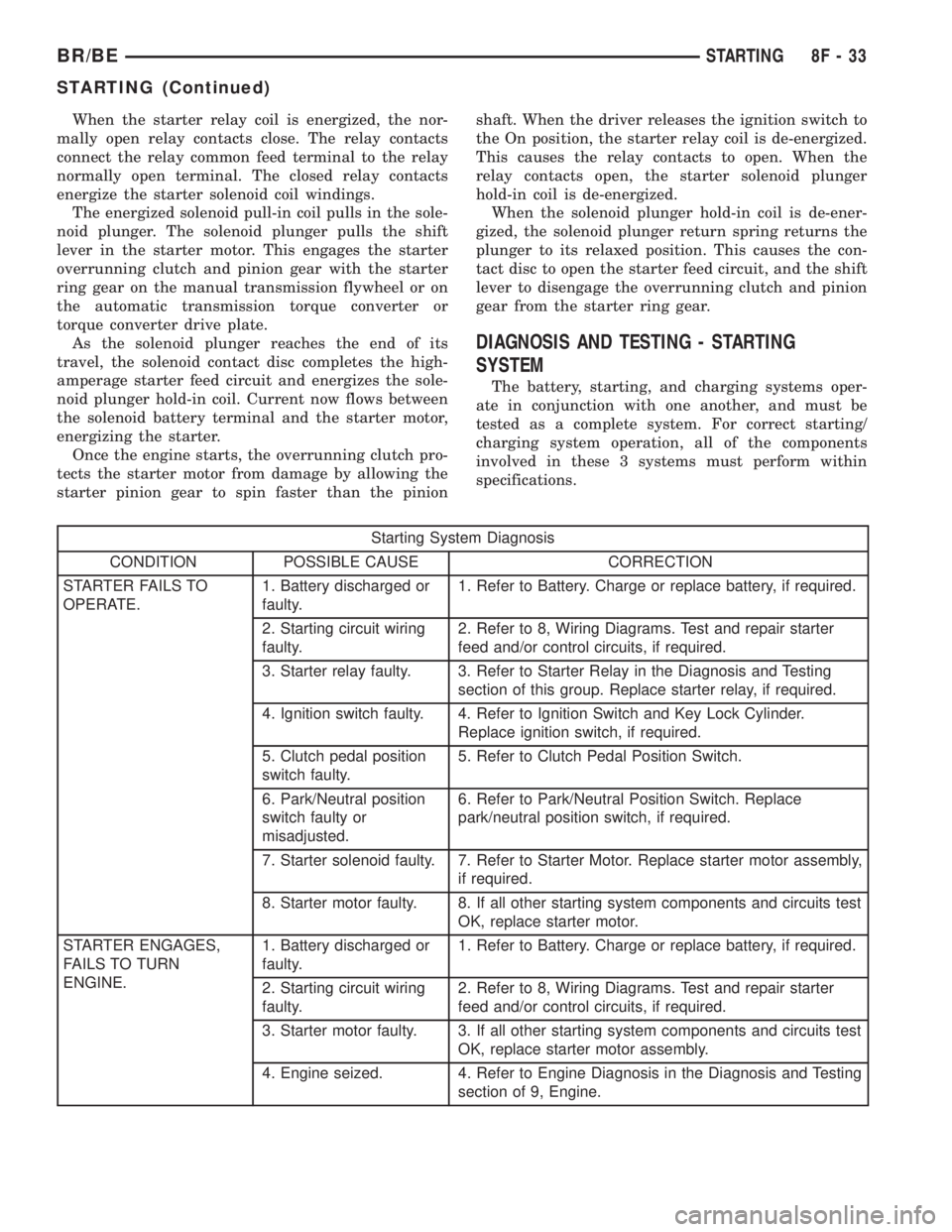
Starting System Diagnosis
CONDITION POSSIBLE CAUSE CORRECTION
STARTER FAILS TO
OPERATE.1. Battery discharged or
faulty.1. Refer to Battery. Charge or replace battery, if required.
2. Starting circuit wiring
faulty.2. Refer to 8, Wiring Diagrams. Test and repair starter
feed and/or control circuits, if required.
3. Starter relay faulty. 3. Refer to Starter Relay in the Diagnosis and Testing
section of this group. Replace starter relay, if required.
4. Ignition switch faulty. 4. Refer to Ignition Switch and Key Lock Cylinder.
Replace ignition switch, if required.
5. Clutch pedal position
switch faulty.5. Refer to Clutch Pedal Position Switch.
6. Park/Neutral position
switch faulty or
misadjusted.6. Refer to Park/Neutral Position Switch. Replace
park/neutral position switch, if required.
7. Starter solenoid faulty. 7. Refer to Starter Motor. Replace starter motor assembly,
if required.
8. Starter motor faulty. 8. If all other starting system components and circuits test
OK, replace starter motor.
STARTER ENGAGES,
FAILS TO TURN
ENGINE.1. Battery discharged or
faulty.1. Refer to Battery. Charge or replace battery, if required.
2. Starting circuit wiring
faulty.2. Refer to 8, Wiring Diagrams. Test and repair starter
feed and/or control circuits, if required.
3. Starter motor faulty. 3. If all other starting system components and circuits test
OK, replace starter motor assembly.
4. Engine seized. 4. Refer to Engine Diagnosis in the Diagnosis and Testing
section of 9, Engine.
BR/BESTARTING 8F - 33
STARTING (Continued)