2001 DODGE RAM Front suspension
[x] Cancel search: Front suspensionPage 63 of 2889

(8) Install a new cotter pin in hub nut. Tighten the
nut as needed to align cotter pin hole in shaft with
the opening in the nut.
(9) Install the rotor, brake caliper with adapter,
(Refer to 5 - BRAKES/HYDRAULIC/MECHANICAL/
DISC BRAKE CALIPERS - INSTALLATION).
(10) Install the ABS wheel speed sensor if
equipped, (Refer to 5 - BRAKES/ELECTRICAL/
FRONT WHEEL SPEED SENSOR - INSTALLA-
TION).
(11) Install the wheel and tire assemblies, (Refer
to 22 - TIRES/WHEELS/WHEELS - STANDARD
PROCEDURE).
(12) Remove the support and lower the vehicle.
(13) Apply the brakes several times to seat the
brake shoes and the caliper piston. Do not move the
vehicle until a firm brake pedal is obtained.
KNUCKLE
DESCRIPTION
The knuckles are a single casting with legs
machined for the upper and lower ball joints. The
knuckles also has machined mounting locations for
the front brake calipers adapters and hub bearing
assembly.
OPERATION
The steering knuckles pivots between the upper
and lower ball joints. The steering linkage is
attached to the knuckles controls vehicle steering.
REMOVAL
(1) Remove hub bearing and axle shaft.
(2) Remove tie-rod or drag link end from the steer-
ing knuckle arm.
(3) Remove the ABS sensor wire and bracket from
knuckle.
(4) Remove the cotter pin from the upper ball stud
nut. Remove the upper and lower ball stud nuts.
(5) Strike the steering knuckle with a brass ham-
mer to loosen. Remove knuckle from axle tube yokes.
REMOVAL
(1) Remove hub bearing and axle shaft.
(2) Remove tie-rod or drag link end from the steer-
ing knuckle arm.
(3) Remove the ABS sensor wire and bracket from
knuckle. Refer to Brakes, for proper procedures.
(4) Remove the cotter pin from the upper ball stud
nut. Remove the upper and lower ball stud nuts.
(5) Strike the steering knuckle with a brass ham-
mer to loosen.
(6) Remove knuckle from axle tube yokes.
INSTALLATION
(1) Position the steering knuckle on the ball studs.
(2) Install and tighten lower ball stud nut to 108
N´m (80 ft. lbs.) torque. Advance nut to next slot to
line up hole and install new cotter pin.
(3) Install and tighten upper ball stud nut to 101
N´m (75 ft. lbs.) torque. Advance nut to next slot to
line up hole and install new cotter pin.
(4) Install the hub bearing and axle shaft.
(5) Install tie-rod or drag link end onto the steer-
ing knuckle arm.
(6) Install the ABS sensor wire and bracket to the
knuckle. Refer to Brakes, for proper procedures.
INSTALLATION
(1) Position the steering knuckle on the ball studs.
(2) Install and tighten lower ball stud nut to 47
N´m (35 ft. lbs.) torque. Do not install cotter pin at
this time.
(3) Install and tighten upper ball stud nut to 94
N´m (70 ft. lbs.) torque. Advance nut to next slot to
line up hole and install new cotter pin.
(4) Retorque lower ball stud nut to 190±217 N´m
(140±160 ft. lbs.) torque. Advance nut to next slot to
line up hole and install new cotter pin.
(5) Install the hub bearing and axle shaft.
(6) Install tie-rod or drag link end onto the steer-
ing knuckle arm.
(7) Install the ABS sensor wire and bracket to the
knuckle. Refer to Brakes, for proper procedure.
LOWER CONTROL ARM
REMOVAL
(1) Raise and support the vehicle.
(2) Paint or scribe alignment marks on the cam
adjusters and suspension arm for installation refer-
ence (Fig. 15).
(3) Remove the lower suspension arm nut, cam
and cam bolt from the axle.
(4) Remove the nut and bolt from the frame rail
bracket and remove the lower suspension arm (Fig.
22).
INSTALLATION
(1) Position the lower suspension arm at the axle
bracket and frame rail bracket.
(2) Install the rear bolt and finger tighten the nut.
(3) Install the cam bolt, cam and nut in the axle
and align the reference marks.
(4) Remove support and lower the vehicle.
(5) Tighten cam nut at the axle bracket to 190
N´m (140 ft. lbs.). Tighten rear nut at the frame
bracket to 190 N´m (140 ft. lbs.).
2 - 20 FRONT - 4WDBR/BE
HUB / BEARING (Continued)
Page 64 of 2889

SHOCK
DESCRIPTION
The shocks are mounted inside the springs and
attached at the top to brackets with grommets. These
brackets are bolted on the frame with three studs on
a ring. The shock is mounted at the bottom of the
axle below the spring seat.
OPERATION
The shock absorbers dampen the jounce and
rebound of the vehicle over various road conditions.
DIAGNOSIS AND TESTING - SHOCK
A knocking or rattling noise from a shock absorber
may be caused by movement between mounting
bushings and metal brackets or attaching compo-
nents. These noises can usually be stopped by tight-
ening the attaching nuts. If the noise persists,
inspect for damaged and worn bushings, and attach-
ing components. Repair as necessary if any of these
conditions exist.
A squeaking noise from the shock absorber may be
caused by the hydraulic valving and may be intermit-
tent. This condition is not repairable and the shock
absorber must be replaced.
The shock absorbers are not refillable or adjust-
able. If a malfunction occurs, the shock absorbermust be replaced. To test a shock absorber, hold it in
an upright position and force the piston in and out of
the cylinder four or five times. The action throughout
each stroke should be smooth and even.
The shock absorber bushings do not require any
type of lubrication. Do not attempt to stop bushing
noise by lubricating them. Grease and mineral oil-
base lubricants will deteriorate the bushing.
REMOVAL
(1) Remove the nut, retainer and grommet from
the upper stud in the engine compartment.
(2) Remove three nuts from the upper shock
bracket (Fig. 16) .
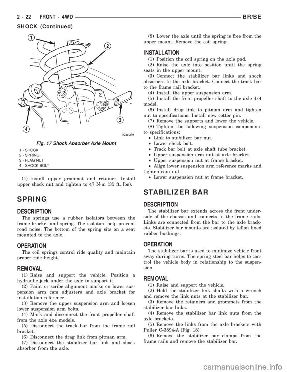
(3) Remove the lower bolt from the axle bracket
(Fig. 17) . Remove the shock absorber from engine
compartment.
INSTALLATION
(1) Position the lower retainer and grommet on the
upper stud. Insert the shock absorber through the
spring from engine compartment.
(2) Install the lower bolt and tighten to 135 N´m
(100 ft. lbs.).
(3) Install the upper shock bracket and three nuts.
Tighten nuts to 75 N´m (55 ft. lbs.).
Fig. 15 Cam Adjuster
1 - ADJUSTMENT CAM
2 - AXLE BRACKET
3 - BRACKET REINFORCEMENT
4 - LOWER SUSPENSION ARM
Fig. 16 Shock Absorber and Bracket
1 - GROMMET
2 - RETAINER
3 - BRACKET
4 - RETAINER
5 - SHOCK
6 - GROMMET
BR/BEFRONT - 4WD 2 - 21
LOWER CONTROL ARM (Continued)
Page 65 of 2889
(4) Install upper grommet and retainer. Install
upper shock nut and tighten to 47 N´m (35 ft. lbs).
SPRING
DESCRIPTION
The springs use a rubber isolators between the
frame bracket and spring. The isolators help prevent
road noise. The bottom of the spring sits on a seat
mounted to the axle.
OPERATION
The coil springs control ride quality and maintain
proper ride height.
REMOVAL
(1) Raise and support the vehicle. Position a
hydraulic jack under the axle to support it.
(2) Paint or scribe alignment marks on lower sus-
pension arm cam adjusters and axle bracket for
installation reference.
(3) Remove the upper suspension arm and loosen
lower suspension arm bolts.
(4) Mark and disconnect the front propeller shaft
from the axle 4x4 models.
(5) Disconnect the track bar from the frame rail
bracket.
(6) Disconnect the drag link from pitman arm.
(7) Disconnect the stabilizer bar link and shock
absorber from the axle.(8) Lower the axle until the spring is free from the
upper mount. Remove the coil spring.
INSTALLATION
(1) Position the coil spring on the axle pad.
(2) Raise the axle into position until the spring
seats in the upper mount.
(3) Connect the stabilizer bar links and shock
absorbers to the axle bracket. Connect the track bar
to the frame rail bracket.
(4) Install the upper suspension arm.
(5) Install the front propeller shaft to the axle 4x4
model.
(6) Install drag link to pitman arm and tighten
nut to specifications. Install new cotter pin.
(7) Remove the supports and lower the vehicle.
(8) Tighten the following suspension components
to specifications:
²Link to stabilizer bar nut.
²Lower shock bolt.
²Track bar bolt at axle shaft tube bracket.
²Upper suspension arm nut at axle bracket.
²Upper suspension nut at frame bracket.
²Align lower suspension arm reference marks and
tighten cam nut.
²Lower suspension nut at frame bracket.
STABILIZER BAR
DESCRIPTION
The stabilizer bar extends across the front under-
side of the chassis and connects to the frame rails.
Links are connected from the bar to the axle brack-
ets. Stabilizer bar mounts are isolated by teflon lined
rubber bushings.
OPERATION
The stabilizer bar is used to minimize vehicle front
sway during turns. The spring steel bar helps to con-
trol the vehicle body in relationship to the suspen-
sion.
REMOVAL
(1) Raise and support the vehicle.
(2) Hold the stabilizer link shafts with a wrench
and remove the link nuts at the stabilizer bar.
(3) Remove the retainers and grommets from the
stabilizer bar links.
(4) Remove the stabilizer bar link nuts from the
axle brackets.
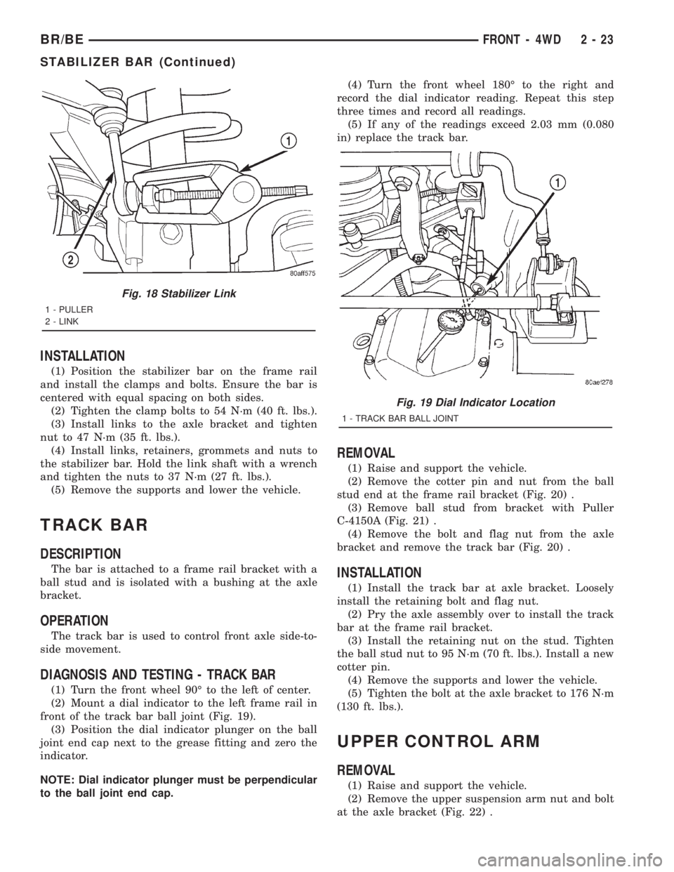
(5) Remove the links from the axle brackets with
Puller C-3894-A (Fig. 18).
(6) Remove the stabilizer bar clamps from the
frame rails and remove the stabilizer bar.
Fig. 17 Shock Absorber Axle Mount
1 - SHOCK
2 - SPRING
3 - FLAG NUT
4 - SHOCK BOLT
2 - 22 FRONT - 4WDBR/BE
SHOCK (Continued)
Page 66 of 2889
INSTALLATION
(1) Position the stabilizer bar on the frame rail
and install the clamps and bolts. Ensure the bar is
centered with equal spacing on both sides.
(2) Tighten the clamp bolts to 54 N´m (40 ft. lbs.).
(3) Install links to the axle bracket and tighten
nut to 47 N´m (35 ft. lbs.).
(4) Install links, retainers, grommets and nuts to
the stabilizer bar. Hold the link shaft with a wrench
and tighten the nuts to 37 N´m (27 ft. lbs.).
(5) Remove the supports and lower the vehicle.
TRACK BAR
DESCRIPTION
The bar is attached to a frame rail bracket with a
ball stud and is isolated with a bushing at the axle
bracket.
OPERATION
The track bar is used to control front axle side-to-
side movement.
DIAGNOSIS AND TESTING - TRACK BAR
(1) Turn the front wheel 90É to the left of center.
(2) Mount a dial indicator to the left frame rail in
front of the track bar ball joint (Fig. 19).
(3) Position the dial indicator plunger on the ball
joint end cap next to the grease fitting and zero the
indicator.
NOTE: Dial indicator plunger must be perpendicular
to the ball joint end cap.(4) Turn the front wheel 180É to the right and
record the dial indicator reading. Repeat this step
three times and record all readings.
(5) If any of the readings exceed 2.03 mm (0.080
in) replace the track bar.
REMOVAL
(1) Raise and support the vehicle.
(2) Remove the cotter pin and nut from the ball
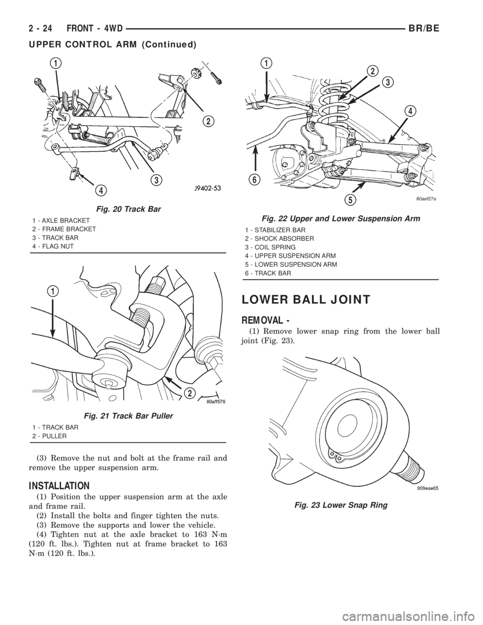
stud end at the frame rail bracket (Fig. 20) .
(3) Remove ball stud from bracket with Puller
C-4150A (Fig. 21) .
(4) Remove the bolt and flag nut from the axle
bracket and remove the track bar (Fig. 20) .
INSTALLATION
(1) Install the track bar at axle bracket. Loosely
install the retaining bolt and flag nut.
(2) Pry the axle assembly over to install the track
bar at the frame rail bracket.
(3) Install the retaining nut on the stud. Tighten
the ball stud nut to 95 N´m (70 ft. lbs.). Install a new
cotter pin.
(4) Remove the supports and lower the vehicle.
(5) Tighten the bolt at the axle bracket to 176 N´m
(130 ft. lbs.).
UPPER CONTROL ARM
REMOVAL
(1) Raise and support the vehicle.
(2) Remove the upper suspension arm nut and bolt
at the axle bracket (Fig. 22) .
Fig. 18 Stabilizer Link
1 - PULLER
2 - LINK
Fig. 19 Dial Indicator Location
1 - TRACK BAR BALL JOINT
BR/BEFRONT - 4WD 2 - 23
STABILIZER BAR (Continued)
Page 67 of 2889
(3) Remove the nut and bolt at the frame rail and
remove the upper suspension arm.
INSTALLATION
(1) Position the upper suspension arm at the axle
and frame rail.
(2) Install the bolts and finger tighten the nuts.
(3) Remove the supports and lower the vehicle.
(4) Tighten nut at the axle bracket to 163 N´m
(120 ft. lbs.). Tighten nut at frame bracket to 163
N´m (120 ft. lbs.).
LOWER BALL JOINT
REMOVAL -
(1) Remove lower snap ring from the lower ball
joint (Fig. 23).
Fig. 20 Track Bar
1 - AXLE BRACKET
2 - FRAME BRACKET
3 - TRACK BAR
4 - FLAG NUT
Fig. 21 Track Bar Puller
1 - TRACK BAR
2 - PULLER
Fig. 22 Upper and Lower Suspension Arm
1 - STABILIZER BAR
2 - SHOCK ABSORBER
3 - COIL SPRING
4 - UPPER SUSPENSION ARM
5 - LOWER SUSPENSION ARM
6 - TRACK BAR
Fig. 23 Lower Snap Ring
2 - 24 FRONT - 4WDBR/BE
UPPER CONTROL ARM (Continued)
Page 69 of 2889
REAR
TABLE OF CONTENTS
page page
REAR
DESCRIPTION...........................26
DIAGNOSIS AND TESTING.................26
SPRING AND SHOCK....................26
SPECIFICATIONS........................27
SPECIAL TOOLS.........................28
BUSHINGS
REMOVAL..............................28
INSTALLATION...........................28
JOUNCE BUMPER
DESCRIPTION...........................28
OPERATION.............................28
SHOCK
DESCRIPTION...........................28OPERATION.............................28
REMOVAL..............................28
INSTALLATION...........................28
SPRING
DESCRIPTION...........................28
OPERATION.............................28
REMOVAL..............................28
INSTALLATION...........................29
STABILIZER BAR
DESCRIPTION...........................30
OPERATION.............................30
REMOVAL..............................30
INSTALLATION...........................30
REAR
DESCRIPTION
The rear suspension is comprised of:
²Shock Absorbers
²Jounce Bumpers
²Stabilizer Bar (optional)
²Leaf Springs
²Drive Axle
CAUTION: A vehicle should always be loaded so
the vehicle weight center-line is located immedi-
ately forward of the rear axle. Correct vehicle load-
ing provides proper front tire-to-road contact. This
results in maximum vehicle handling stability and
safety. Incorrect vehicle weight distribution can
cause excessive tire tread wear, spring fatigue or
failure, and erratic steering.
CAUTION: Suspension components with rubber/ure-
thane bushings (except stabilizer bar) should be
tightened with the vehicle at normal ride height. It is
important to have the springs supporting the weight
of the vehicle when the fasteners are torqued. If
springs are not at their normal ride position, vehicle
ride comfort could be affected and premature bush-
ing wear may occur.
DIAGNOSIS AND TESTING - SPRING AND
SHOCK
A knocking or rattling noise from a shock absorber
may be caused by movement between mounting
bushings and metal brackets or attaching compo-
nents. These noises can usually be stopped by tight-
ening the attaching nuts. If the noise persists,
inspect for damaged and worn bushings, and attach-
ing components. Repair as necessary if any of these
conditions exist.
A squeaking noise from the shock absorber may be
caused by the hydraulic valving and may be intermit-
tent. This condition is not repairable and the shock
absorber must be replaced.
The shock absorbers are not refillable or adjust-
able. If a malfunction occurs, the shock absorber
must be replaced. To test a shock absorber, hold it in
an upright position and force the piston in and out of
the cylinder four or five times. The action throughout
each stroke should be smooth and even.
The spring eye and shock absorber bushings do not
require any type of lubrication. Do not attempt to
stop spring bushing noise by lubricating them.
Grease and mineral oil-base lubricants will deterio-
rate the bushing rubber.
If the vehicle is used for severe, off-road operation,
the springs should be examined periodically. Check
for broken and shifted leafs, loose and missing clips,
and broken center bolts. Refer to Spring and Shock
Absorber Diagnosis chart for additional information.
2 - 26 REARBR/BE
Page 90 of 2889
(8) Disconnect the stabilizer bar links at the axle
brackets.
(9) Disconnect the shock absorbers from axle
brackets.
(10) Disconnect the track bar from the axle
bracket.
(11) Disconnect the tie rod and drag link from the
steering knuckles.
(12) Position the axle with a suitable lifting device
under the axle assembly.
(13) Secure axle to lifting device.
(14) Mark suspension alignment cams for installa-
tion reference.
(15) Disconnect the upper and lower suspension
arms from the axle bracket.
(16) Lower the axle. The coil springs will drop
with the axle.
(17) Remove the coil springs from the axle bracket.
INSTALLATION
CAUTION: Suspension components with rubber
bushings should be tightened with the weight of the
vehicle on the suspension, at normal height. If
springs are not at their normal ride position, vehicle
ride comfort could be affected and premature bush-
ing wear may occur. Rubber bushings must never
be lubricated.
(1) Support the axle on a suitable lifting device.
(2) Secure axle to lifting device.
(3) Position the axle under the vehicle.
(4) Install the springs, retainer clip and bolts.
(5) Raise the axle and align it with the spring
pads.
(6) Position the upper and lower suspension arms
in the axle brackets. Install bolts, nuts and align the
suspension alignment cams to the reference marks.
Do not tighten at this time.
(7) Connect the track bar to the axle bracket and
install the bolt. Do not tighten at this time.
(8) Install the shock absorber and tighten bolts to
121 N´m (89 ft. lbs.) torque.
(9) Install the stabilizer bar link to the axle
bracket. Tighten the nut to 37 N´m (27 ft. lbs.)
torque.
(10) Install the drag link and tie rod to the steer-
ing knuckles and tighten the nuts to 88 N´m (65 ft.
lbs.) torque.
(11) Install the ABS wheel speed sensors, if
equipped. Refer to group 5, Brakes, for proper proce-
dures.
(12) Install the brake calipers and rotors. Refer to
Group 5, Brakes, for proper procedures.
(13) Connect the vent hose to the tube fitting.
(14) Connect vacuum hose and electrical connector
to disconnect housing.(15) Install front propeller shaft.
(16) Check and add differential lubricant, if neces-
sary. Refer to Lubricant Specifications in this section
for lubricant requirements.
(17) Install the wheel and tire assemblies.
(18) Remove the supports and lower the vehicle.
(19) Tighten the upper suspension arm nuts at
axle to 121 N´m (89 ft. lbs.) torque. Tighten the
upper suspension arm nuts at frame to 84 N´m (62 ft.
lbs.) torque.
(20) Tighten the lower suspension arm nuts at
axle to 84 N´m (62 ft. lbs.) torque. Tighten the lower
suspension arm nuts at frame to 119 N´m (88 ft. lbs.)
torque.
(21) Tighten the track bar bolt at the axle bracket
to 176 N´m (130 ft. lbs.) torque.
(22) Check the front wheel alignment.
ADJUSTMENTS
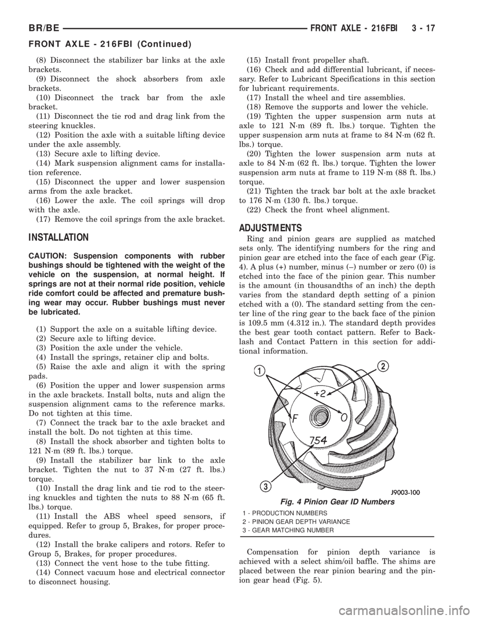
Ring and pinion gears are supplied as matched
sets only. The identifying numbers for the ring and
pinion gear are etched into the face of each gear (Fig.
4). A plus (+) number, minus (±) number or zero (0) is
etched into the face of the pinion gear. This number
is the amount (in thousandths of an inch) the depth
varies from the standard depth setting of a pinion
etched with a (0). The standard setting from the cen-
ter line of the ring gear to the back face of the pinion
is 109.5 mm (4.312 in.). The standard depth provides
the best gear tooth contact pattern. Refer to Back-
lash and Contact Pattern in this section for addi-
tional information.
Compensation for pinion depth variance is
achieved with a select shim/oil baffle. The shims are
placed between the rear pinion bearing and the pin-
ion gear head (Fig. 5).
Fig. 4 Pinion Gear ID Numbers
1 - PRODUCTION NUMBERS
2 - PINION GEAR DEPTH VARIANCE
3 - GEAR MATCHING NUMBER
BR/BEFRONT AXLE - 216FBI 3 - 17
FRONT AXLE - 216FBI (Continued)
Page 123 of 2889

REMOVAL
(1) Raise and support the vehicle.
(2) Remove the wheels and tires.
(3) Remove the brake calipers and rotors. Refer to
Group 5, Brakes, for proper procedures.
(4) Remove ABS wheel speed sensors, if equipped.
Refer to Group 5, Brakes, for proper procedures.
(5) Disconnect the axle vent hose.
(6) Disconnect vacuum hose and electrical connec-
tor at disconnect housing.
(7) Remove the front propeller shaft.
(8) Disconnect the stabilizer bar links at the axle
brackets.
(9) Disconnect the shock absorbers from axle
brackets.
(10) Disconnect the track bar from the axle
bracket.
(11) Disconnect the tie rod and drag link from the
steering knuckles.
(12) Position the axle with a suitable lifting device
under the axle assembly.
(13) Secure axle to lifting device.
(14) Mark suspension alignment cams for installa-
tion reference.
(15) Disconnect the upper and lower suspension
arms from the axle bracket.
(16) Lower the axle. The coil springs will drop
with the axle.
(17) Remove the coil springs from the axle bracket.
INSTALLATION
CAUTION: Suspension components with rubber
bushings should be tightened with the weight of the
vehicle on the suspension, at normal height. If
springs are not at their normal ride position, vehicle
ride comfort could be affected and premature bush-
ing wear may occur. Rubber bushings must never
be lubricated.
(1) Support the axle on a suitable lifting device.
(2) Secure axle to lifting device.
(3) Position the axle under the vehicle.
(4) Install the springs, retainer clip and bolts.
(5) Raise the axle and align it with the spring
pads.
(6) Position the upper and lower suspension arms
in the axle brackets. Install bolts, nuts and align the
suspension alignment cams to the reference marks.
Do not tighten at this time.
(7) Connect the track bar to the axle bracket and
install the bolt. Do not tighten at this time.
(8) Install the shock absorber and tighten bolts to
121 N´m (89 ft. lbs.) torque.(9) Install the stabilizer bar link to the axle
bracket. Tighten the nut to 37 N´m (27 ft. lbs.)
torque.
(10) Install the drag link and tie rod to the steer-
ing knuckles and tighten the nuts to 88 N´m (65 ft.
lbs.) torque.
(11) Install the ABS wheel speed sensors, if
equipped. Refer to group 5, Brakes, for proper proce-
dures.
(12) Install the brake calipers and rotors. Refer to
Group 5, Brakes, for proper procedures.
(13) Connect the vent hose to the tube fitting.
(14) Connect vacuum hose and electrical connector
to disconnect housing.
(15) Install front propeller shaft.
(16) Check and add differential lubricant, if neces-
sary. Refer to Lubricant Specifications in this section
for lubricant requirements.
(17) Install the wheel and tire assemblies.
(18) Remove the supports and lower the vehicle.
(19) Tighten the upper suspension arm nuts at
axle to 121 N´m (89 ft. lbs.) torque. Tighten the
upper suspension arm nuts at frame to 84 N´m (62 ft.
lbs.) torque.
(20) Tighten the lower suspension arm nuts at
axle to 84 N´m (62 ft. lbs.) torque. Tighten the lower
suspension arm nuts at frame to 119 N´m (88 ft. lbs.)
torque.
(21) Tighten the track bar bolt at the axle bracket
to 176 N´m (130 ft. lbs.) torque.
(22) Check the front wheel alignment.ADJUSTMENTS
Ring and pinion gears are supplied as matched
sets only. The identifying numbers for the ring and
pinion gear are etched into the face of each gear (Fig.
4). A plus (+) number, minus (±) number or zero (0) is
etched into the face of the pinion gear. This number
is the amount (in thousandths of an inch) the depth
varies from the standard depth setting of a pinion
etched with a (0). The standard setting from the cen-
ter line of the ring gear to the back face of the pinion
is 127 mm (5.00 in.). The standard depth provides
the best gear tooth contact pattern. Refer to Back-
lash and Contact Pattern in this section for addi-
tional information.
Compensation for pinion depth variance is
achieved with a select shim/oil baffle. The shims are
placed between the rear pinion bearing and the pin-
ion gear head (Fig. 5).
If a new gear set is being installed, note the depth
variance etched into both the original and replace-
ment pinion. Add or subtract this number from the
thickness of the original depth shim/oil slinger to
compensate for the difference in the depth variances.
Refer to the Depth Variance chart.
3 - 50 FRONT AXLE - 248FBIBR/BE
FRONT AXLE - 248FBI (Continued)