2001 DODGE RAM warning
[x] Cancel search: warningPage 272 of 2889
BRAKES
TABLE OF CONTENTS
page page
BRAKES - BASE
SPECIFICATIONS.........................2
SPECIAL TOOLS..........................4
HYDRAULIC/MECHANICAL
DESCRIPTION............................4
WARNING.............................5
DIAGNOSIS AND TESTING..................5
BASE BRAKE SYSTEM...................5
STANDARD PROCEDURE...................7
MANUAL BLEEDING.....................7
PRESSURE BLEEDING...................8
BRAKE LINES
STANDARD PROCEDURE...................8
DOUBLE INVERTED FLARING..............8
ISO FLARING...........................8
COMBINATION VALVE
DESCRIPTION............................9
OPERATION.............................9
DIAGNOSIS AND TESTING..................9
COMBINATION VALVE....................9
REMOVAL..............................10
INSTALLATION...........................10
DISC BRAKE CALIPERS
REMOVAL..............................10
DISASSEMBLY...........................11
CLEANING..............................12
INSPECTION............................12
ASSEMBLY.............................12
INSTALLATION...........................13
FLUID
DIAGNOSIS AND TESTING.................14
BRAKE FLUID CONTAMINATION...........14
STANDARD PROCEDURE..................14
BRAKE FLUID LEVEL....................14
SPECIFICATIONS........................15
FLUID RESERVOIR
REMOVAL..............................15
INSTALLATION...........................15
PEDAL
DESCRIPTION...........................16
OPERATION.............................16
REMOVAL..............................16
INSTALLATION...........................17
POWER BRAKE BOOSTER
DIAGNOSIS AND TESTING.................17
HYDRAULIC BOOSTER..................17
STANDARD PROCEDURE..................19
POWER BRAKE BOOSTER...............19
REMOVAL..............................19INSTALLATION...........................20
ROTORS
DIAGNOSIS AND TESTING.................20
DISC BRAKE ROTOR....................20
REMOVAL..............................21
INSTALLATION...........................22
BRAKE PADS/SHOES
REMOVAL..............................23
INSTALLATION...........................26
MASTER CYLINDER
DESCRIPTION...........................29
OPERATION.............................29
DIAGNOSIS AND TESTING.................29
MASTER CYLINDER/POWER BOOSTER.....29
STANDARD PROCEDURE..................30
MASTER CYLINDER BLEEDING...........30
REMOVAL..............................30
INSTALLATION...........................30
WHEEL CYLINDERS
REMOVAL..............................31
DISASSEMBLY...........................31
CLEANING..............................31
INSPECTION............................31
ASSEMBLY.............................31
INSTALLATION...........................32
SUPPORT PLATE
REMOVAL..............................32
INSTALLATION...........................32
DRUM
DESCRIPTION...........................32
OPERATION.............................32
DIAGNOSIS AND TESTING.................33
BRAKE DRUM.........................33
STANDARD PROCEDURE..................33
BRAKE DRUM MACHINING...............33
CLEANING..............................33
INSPECTION............................33
ADJUSTMENTS..........................34
PARKING BRAKE
DESCRIPTION...........................35
OPERATION.............................36
PEDAL
REMOVAL..............................36
INSTALLATION...........................36
CABLES
REMOVAL..............................37
INSTALLATION...........................38
CABLE TENSIONER
ADJUSTMENTS..........................40
BR/BEBRAKES 5 - 1
Page 276 of 2889
WARNING
WARNING: DUST AND DIRT ACCUMULATING ON
BRAKE PARTS DURING NORMAL USE MAY CON-
TAIN ASBESTOS FIBERS FROM PRODUCTION OR
AFTERMARKET LININGS. BREATHING EXCESSIVE
CONCENTRATIONS OF ASBESTOS FIBERS CAN
CAUSE SERIOUS BODILY HARM. EXERCISE CARE
WHEN SERVICING BRAKE PARTS. DO NOT CLEAN
BRAKE PARTS WITH COMPRESSED AIR OR BY
DRY BRUSHING. USE A VACUUM CLEANER SPE-
CIFICALLY DESIGNED FOR THE REMOVAL OF
ASBESTOS FIBERS FROM BRAKE COMPONENTS.
IF A SUITABLE VACUUM CLEANER IS NOT AVAIL-
ABLE, CLEANING SHOULD BE DONE WITH A
WATER DAMPENED CLOTH. DO NOT SAND, OR
GRIND BRAKE LINING UNLESS EQUIPMENT USED
IS DESIGNED TO CONTAIN THE DUST RESIDUE.
DISPOSE OF ALL RESIDUE CONTAINING ASBES-
TOS FIBERS IN SEALED BAGS OR CONTAINERS
TO MINIMIZE EXPOSURE TO YOURSELF AND OTH-
ERS. FOLLOW PRACTICES PRESCRIBED BY THE
OCCUPATIONAL SAFETY AND HEALTH ADMINIS-
TRATION AND THE ENVIRONMENTAL PROTECTION
AGENCY FOR THE HANDLING, PROCESSING, AND
DISPOSITION OF DUST OR DEBRIS THAT MAY
CONTAIN ASBESTOS FIBERS.
CAUTION: Never use gasoline, kerosene, alcohol,
motor oil, transmission fluid, or any fluid containing
mineral oil to clean the system components. These
fluids damage rubber cups and seals. Use only
fresh brake fluid or Mopar brake cleaner to clean or
flush brake system components. These are the only
cleaning materials recommended. If system contam-
ination is suspected, check the fluid for dirt, discol-
oration, or separation into distinct layers. Also
check the reservoir cap seal for distortion. Drain
and flush the system with new brake fluid if con-
tamination is suspected.
CAUTION: Use Mopar brake fluid, or an equivalent
quality fluid meeting SAE/DOT standards J1703 and
DOT 3. Brake fluid must be clean and free of con-
taminants. Use fresh fluid from sealed containers
only to ensure proper antilock component opera-
tion.
CAUTION: Use Mopar multi-mileage or high temper-
ature grease to lubricate caliper slide surfaces,
drum brake pivot pins, and shoe contact points on
the backing plates. Use multi-mileage grease or GE
661 or Dow 111 silicone grease on caliper slide pins
to ensure proper operation.
DIAGNOSIS AND TESTING - BASE BRAKE
SYSTEM
Base brake components consist of the brake shoes,
calipers, wheel cylinders, brake drums, rotors, brake
lines, master cylinder, booster, and parking brake
components.
Brake diagnosis involves determining if the prob-
lem is related to a mechanical, hydraulic, or vacuum
operated component.
The first diagnosis step is the preliminary check.
PRELIMINARY BRAKE CHECK
(1) Check condition of tires and wheels. Damaged
wheels and worn, damaged, or underinflated tires
can cause pull, shudder, vibration, and a condition
similar to grab.
(2) If complaint was based on noise when braking,
check suspension components. Jounce front and rear
of vehicle and listen for noise that might be caused
by loose, worn or damaged suspension or steering
components.
(3) Inspect brake fluid level and condition. Note
that the brake reservoir fluid level will decrease in
proportion to normal lining wear.Also note that
brake fluid tends to darken over time. This is
normal and should not be mistaken for contam-
ination.
(a) If fluid level is abnormally low, look for evi-
dence of leaks at calipers, wheel cylinders, brake
lines, and master cylinder.
(b) If fluid appears contaminated, drain out a
sample to examine. System will have to be flushed
if fluid is separated into layers, or contains a sub-
stance other than brake fluid. The system seals
and cups will also have to be replaced after flush-
ing. Use clean brake fluid to flush the system.
(4) Check parking brake operation. Verify free
movement and full release of cables and pedal. Also
note if vehicle was being operated with parking
brake partially applied.
(5) Check brake pedal operation. Verify that pedal
does not bind and has adequate free play. If pedal
lacks free play, check pedal and power booster for
being loose or for bind condition. Do not road test
until condition is corrected.
(6) Check booster vacuum check valve and hose.
(7) If components checked appear OK, road test
the vehicle.
ROAD TESTING
(1) If complaint involved low brake pedal, pump
pedal and note if it comes back up to normal height.
(2) Check brake pedal response with transmission
in Neutral and engine running. Pedal should remain
firm under constant foot pressure.
BR/BEBRAKES 5 - 5
HYDRAULIC/MECHANICAL (Continued)
Page 280 of 2889
tube can be used for emergency repair when factory
replacement parts are not readily available.
To make a ISO flare use an ISO flaring tool kit.
(1) Cut off damaged tube with Tubing Cutter.
(2) Remove any burrs from the inside of the tube.
(3) Install tube nut on the tube.
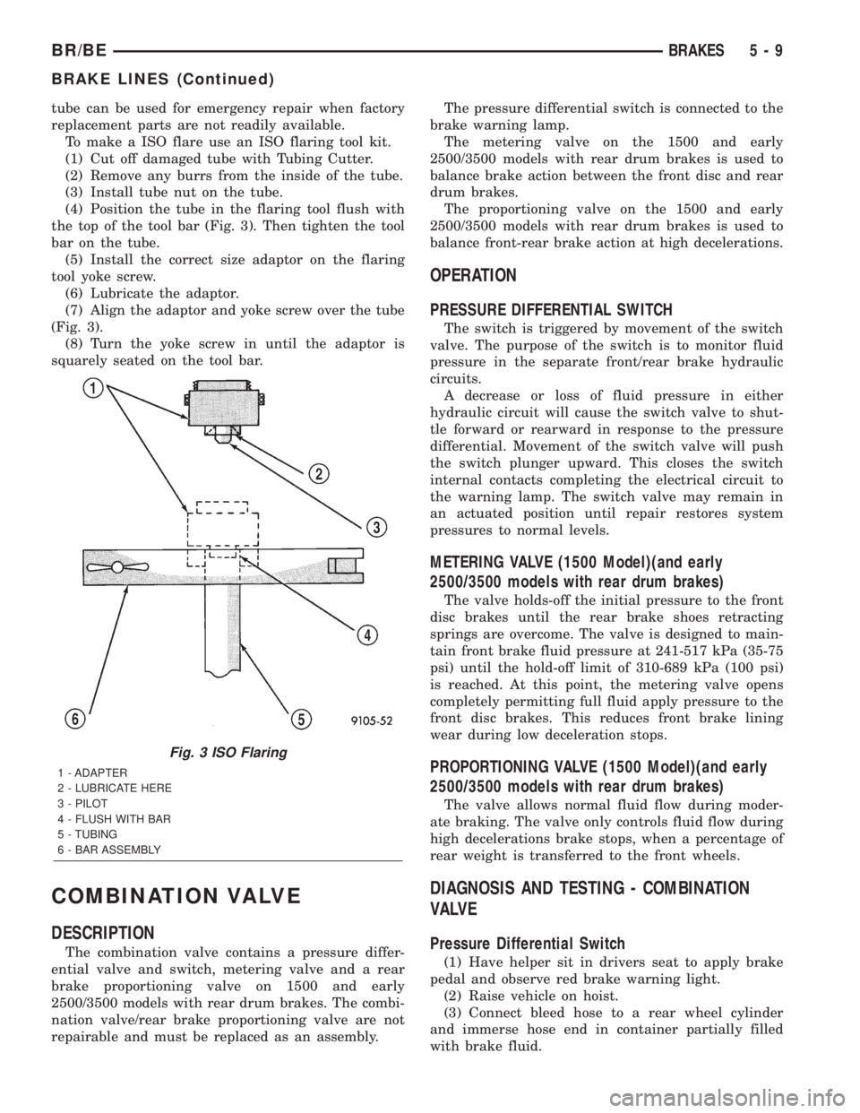
(4) Position the tube in the flaring tool flush with
the top of the tool bar (Fig. 3). Then tighten the tool
bar on the tube.
(5) Install the correct size adaptor on the flaring
tool yoke screw.
(6) Lubricate the adaptor.
(7) Align the adaptor and yoke screw over the tube
(Fig. 3).
(8) Turn the yoke screw in until the adaptor is
squarely seated on the tool bar.
COMBINATION VALVE
DESCRIPTION
The combination valve contains a pressure differ-
ential valve and switch, metering valve and a rear
brake proportioning valve on 1500 and early
2500/3500 models with rear drum brakes. The combi-
nation valve/rear brake proportioning valve are not
repairable and must be replaced as an assembly.The pressure differential switch is connected to the
brake warning lamp.
The metering valve on the 1500 and early
2500/3500 models with rear drum brakes is used to
balance brake action between the front disc and rear
drum brakes.
The proportioning valve on the 1500 and early
2500/3500 models with rear drum brakes is used to
balance front-rear brake action at high decelerations.
OPERATION
PRESSURE DIFFERENTIAL SWITCH
The switch is triggered by movement of the switch
valve. The purpose of the switch is to monitor fluid
pressure in the separate front/rear brake hydraulic
circuits.
A decrease or loss of fluid pressure in either
hydraulic circuit will cause the switch valve to shut-
tle forward or rearward in response to the pressure
differential. Movement of the switch valve will push
the switch plunger upward. This closes the switch
internal contacts completing the electrical circuit to
the warning lamp. The switch valve may remain in
an actuated position until repair restores system
pressures to normal levels.
METERING VALVE (1500 Model)(and early
2500/3500 models with rear drum brakes)
The valve holds-off the initial pressure to the front
disc brakes until the rear brake shoes retracting
springs are overcome. The valve is designed to main-
tain front brake fluid pressure at 241-517 kPa (35-75
psi) until the hold-off limit of 310-689 kPa (100 psi)
is reached. At this point, the metering valve opens
completely permitting full fluid apply pressure to the
front disc brakes. This reduces front brake lining
wear during low deceleration stops.
PROPORTIONING VALVE (1500 Model)(and early
2500/3500 models with rear drum brakes)
The valve allows normal fluid flow during moder-
ate braking. The valve only controls fluid flow during
high decelerations brake stops, when a percentage of
rear weight is transferred to the front wheels.
DIAGNOSIS AND TESTING - COMBINATION
VALVE
Pressure Differential Switch
(1) Have helper sit in drivers seat to apply brake
pedal and observe red brake warning light.
(2) Raise vehicle on hoist.
(3) Connect bleed hose to a rear wheel cylinder
and immerse hose end in container partially filled
with brake fluid.
Fig. 3 ISO Flaring
1 - ADAPTER
2 - LUBRICATE HERE
3 - PILOT
4 - FLUSH WITH BAR
5 - TUBING
6 - BAR ASSEMBLY
BR/BEBRAKES 5 - 9
BRAKE LINES (Continued)
Page 281 of 2889
(4) Have helper press and hold brake pedal to floor
and observe warning light.
(a) If warning light illuminates, switch is operat-
ing correctly.
(b) If light fails to illuminate, check circuit fuse,
bulb, and wiring. The parking brake switch can be
used to aid in identifying whether or not the brake
light bulb and fuse is functional. Repair or replace
parts as necessary and test differential pressure
switch operation again.
(5) If warning light still does not illuminate,
switch is faulty. Replace combination valve assembly,
bleed brake system and verify proper switch and
valve operation.
REMOVAL
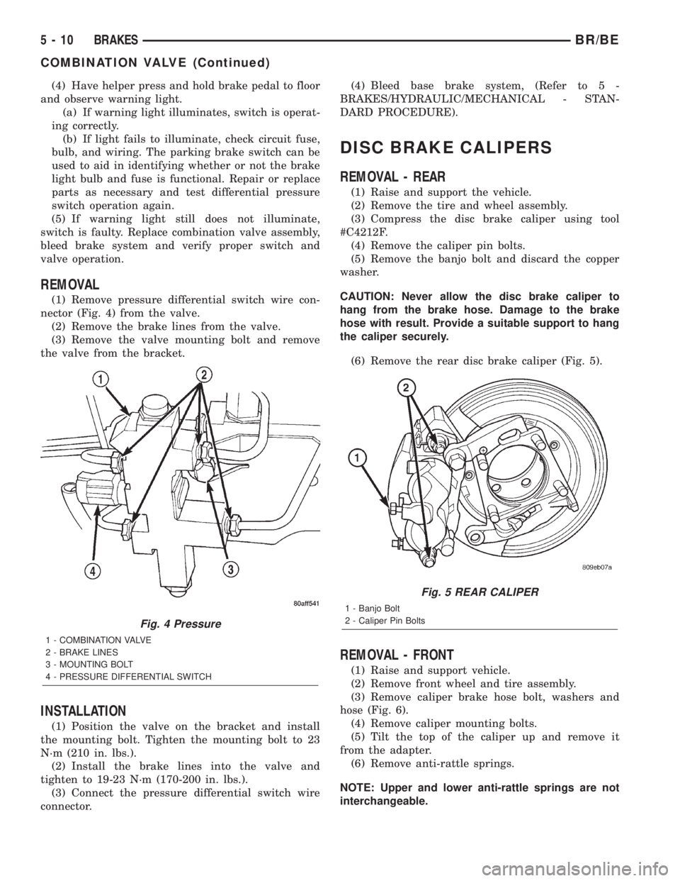
(1) Remove pressure differential switch wire con-
nector (Fig. 4) from the valve.
(2) Remove the brake lines from the valve.
(3) Remove the valve mounting bolt and remove
the valve from the bracket.
INSTALLATION
(1) Position the valve on the bracket and install
the mounting bolt. Tighten the mounting bolt to 23
N´m (210 in. lbs.).
(2) Install the brake lines into the valve and
tighten to 19-23 N´m (170-200 in. lbs.).
(3) Connect the pressure differential switch wire
connector.(4) Bleed base brake system, (Refer to 5 -
BRAKES/HYDRAULIC/MECHANICAL - STAN-
DARD PROCEDURE).
DISC BRAKE CALIPERS
REMOVAL - REAR
(1) Raise and support the vehicle.
(2) Remove the tire and wheel assembly.
(3) Compress the disc brake caliper using tool
#C4212F.
(4) Remove the caliper pin bolts.
(5) Remove the banjo bolt and discard the copper
washer.
CAUTION: Never allow the disc brake caliper to
hang from the brake hose. Damage to the brake
hose with result. Provide a suitable support to hang
the caliper securely.
(6) Remove the rear disc brake caliper (Fig. 5).
REMOVAL - FRONT
(1) Raise and support vehicle.
(2) Remove front wheel and tire assembly.
(3) Remove caliper brake hose bolt, washers and
hose (Fig. 6).
(4) Remove caliper mounting bolts.
(5) Tilt the top of the caliper up and remove it
from the adapter.
(6) Remove anti-rattle springs.
NOTE: Upper and lower anti-rattle springs are not
interchangeable.
Fig. 4 Pressure
1 - COMBINATION VALVE
2 - BRAKE LINES
3 - MOUNTING BOLT
4 - PRESSURE DIFFERENTIAL SWITCH
Fig. 5 REAR CALIPER
1 - Banjo Bolt
2 - Caliper Pin Bolts
5 - 10 BRAKESBR/BE
COMBINATION VALVE (Continued)
Page 282 of 2889
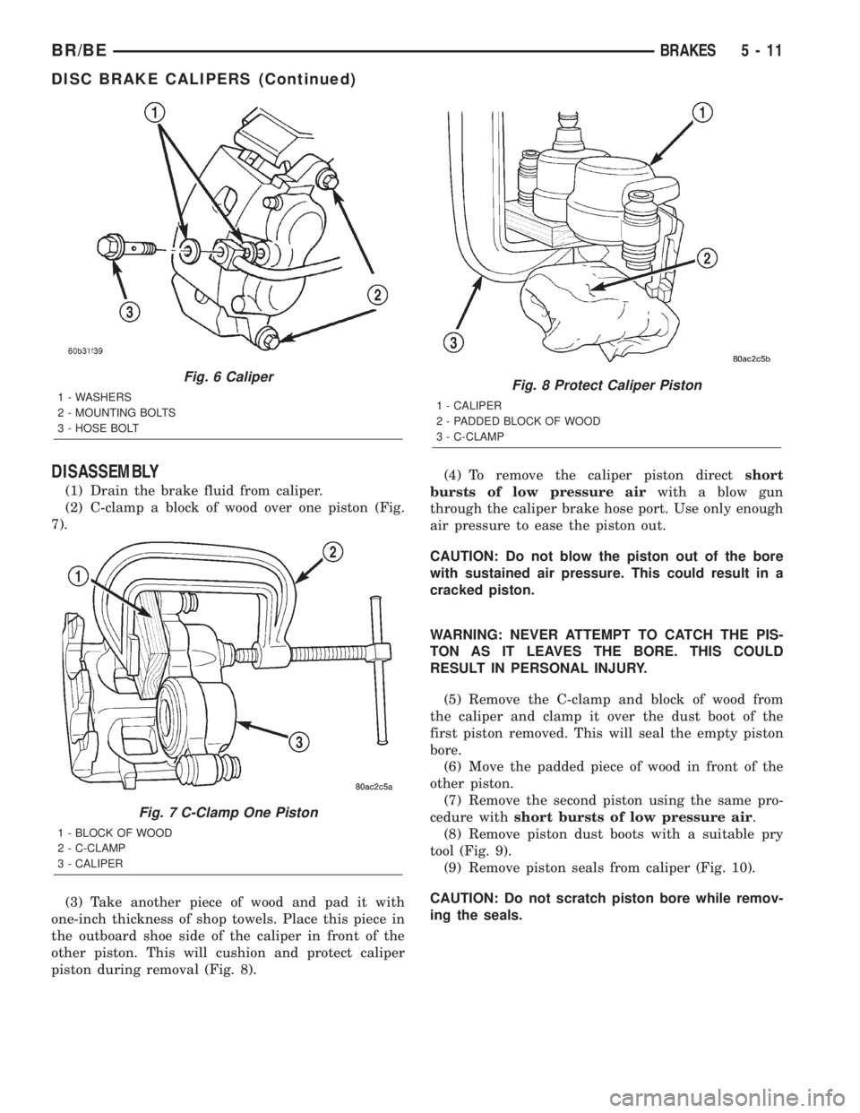
DISASSEMBLY
(1) Drain the brake fluid from caliper.
(2) C-clamp a block of wood over one piston (Fig.
7).
(3) Take another piece of wood and pad it with
one-inch thickness of shop towels. Place this piece in
the outboard shoe side of the caliper in front of the
other piston. This will cushion and protect caliper
piston during removal (Fig. 8).(4) To remove the caliper piston directshort
bursts of low pressure airwith a blow gun
through the caliper brake hose port. Use only enough
air pressure to ease the piston out.
CAUTION: Do not blow the piston out of the bore
with sustained air pressure. This could result in a
cracked piston.
WARNING: NEVER ATTEMPT TO CATCH THE PIS-
TON AS IT LEAVES THE BORE. THIS COULD
RESULT IN PERSONAL INJURY.
(5) Remove the C-clamp and block of wood from
the caliper and clamp it over the dust boot of the
first piston removed. This will seal the empty piston
bore.
(6) Move the padded piece of wood in front of the
other piston.
(7) Remove the second piston using the same pro-
cedure withshort bursts of low pressure air.
(8) Remove piston dust boots with a suitable pry
tool (Fig. 9).
(9) Remove piston seals from caliper (Fig. 10).
CAUTION: Do not scratch piston bore while remov-
ing the seals.
Fig. 6 Caliper
1 - WASHERS
2 - MOUNTING BOLTS
3 - HOSE BOLT
Fig. 7 C-Clamp One Piston
1 - BLOCK OF WOOD
2 - C-CLAMP
3 - CALIPER
Fig. 8 Protect Caliper Piston
1 - CALIPER
2 - PADDED BLOCK OF WOOD
3 - C-CLAMP
BR/BEBRAKES 5 - 11
DISC BRAKE CALIPERS (Continued)
Page 290 of 2889
STANDARD PROCEDURE - BLEEDING
The hydraulic booster is generally self-bleeding,
this procedure will normally bleed the air from the
booster. Normal driving and operation of the unit will
remove any remaining trapped air.
(1) Fill power steering pump reservoir.
(2) Disconnect fuel shutdown relay and crank the
engine for several seconds, Refer to Fuel System for
relay location and WARNING.
(3) Check fluid level and add if necessary.
(4) Connect fuel shutdown relay and start the
engine.
(5) Turn the steering wheel slowly from lock to
lock twice.
(6) Stop the engine and discharge the accumulator
by depressing the brake pedal 5 times.
(7) Start the engine and turn the steering wheel
slowly from lock to lock twice.
(8) Turn off the engine and check fluid level and
add if necessary.
NOTE: If fluid foaming occurs, wait for foam to dis-
sipate and repeat steps 7 and 8.
REMOVAL
NOTE: If the booster is being replaced because the
power steering fluid is contaminated, flush the
power steering system before replacing the booster.
(1) With engine off depress the brake pedal 5
times to discharge the accumulator.
(2) Remove brake lines from master cylinder.
(3) Remove mounting nuts from the master cylin-
der.
(4) Remove the bracket from the hydraulic booster
lines and master cylinder mounting studs.
(5) Remove the master cylinder.
(6) Remove the return hose and the two pressure
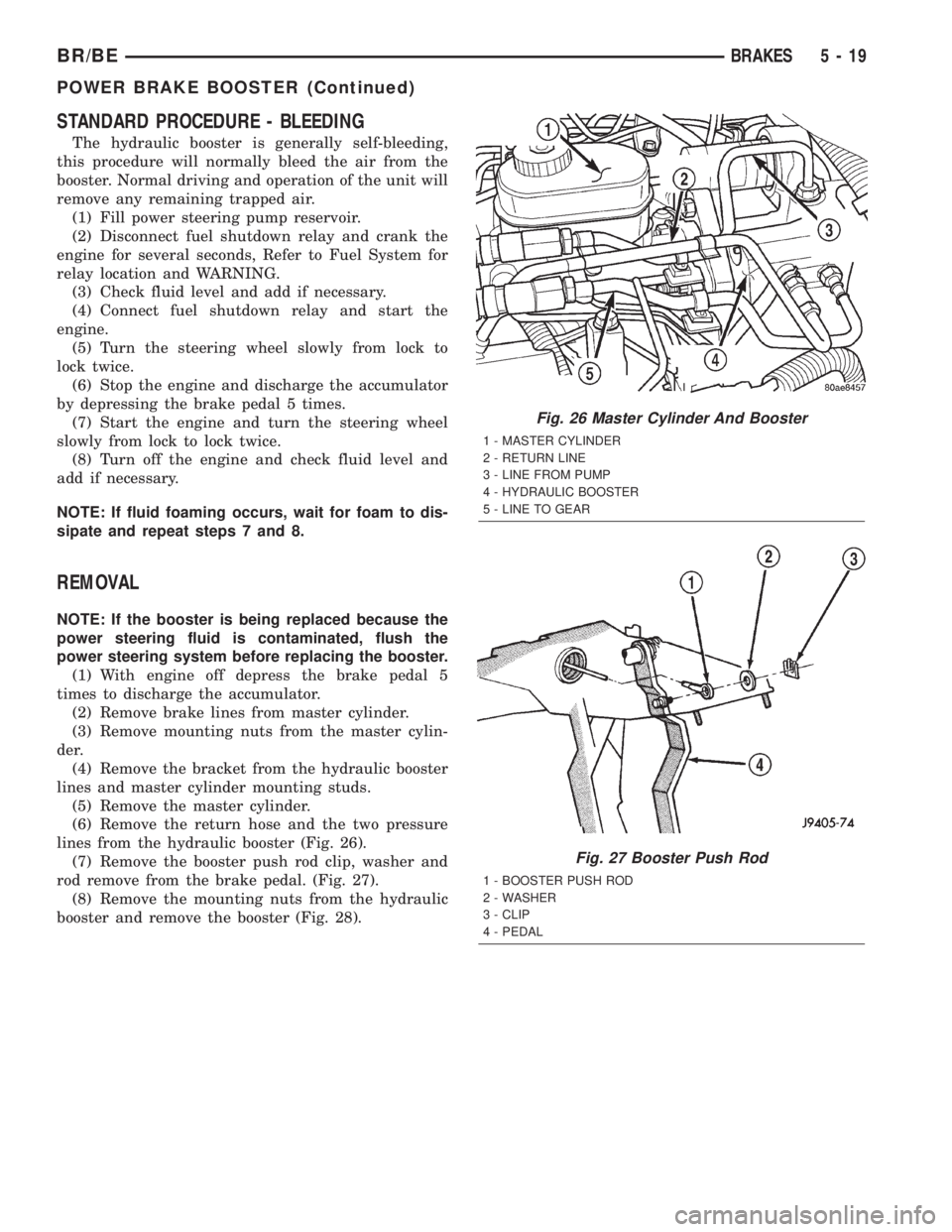
lines from the hydraulic booster (Fig. 26).
(7) Remove the booster push rod clip, washer and
rod remove from the brake pedal. (Fig. 27).
(8) Remove the mounting nuts from the hydraulic
booster and remove the booster (Fig. 28).
Fig. 26 Master Cylinder And Booster
1 - MASTER CYLINDER
2 - RETURN LINE
3 - LINE FROM PUMP
4 - HYDRAULIC BOOSTER
5 - LINE TO GEAR
Fig. 27 Booster Push Rod
1 - BOOSTER PUSH ROD
2 - WASHER
3 - CLIP
4 - PEDAL
BR/BEBRAKES 5 - 19
POWER BRAKE BOOSTER (Continued)
Page 307 of 2889
OPERATION - 2500/3500 WITH REAR DISC
BRAKES
To apply the parking brake the pedal is depressed.
This creates tension in the cable which pulls forward
on the park brake lever. The lever pushes the park
brake shoes outward and into contact with the drum
section of the rotor. The contact of shoe to rotor parks
the vehicle.
A torsion locking mechanism is used to hold the
pedal in an applied position. Parking brake release is
accomplished by the hand release.
A parking brake switch is mounted on the parking
brake lever and is actuated by movement of the
lever. The switch, which is in circuit with the red
warning light in the dash, will illuminate the warn-
ing light whenever the parking brake is applied.
Parking brake adjustment is controlled by a cable
tensioner mechanism. The cable tensioner, once
adjusted at the factory, should not need further
adjustment under normal circumstances. Adjustment
may be required if a new tensioner, or cables are
installed, or disconnected.
OPERATION - (1500 models) (Early 2500/3500
models with rear drum brakes)
To apply the parking brakes, the pedal is
depressed. This pulls the rear brake shoe actuating
levers forward. As the actuating lever is pulled for-
ward, the parking brake strut or cam, exerts a linear
force against the primary brake shoe. This action
presses the primary shoe into contact with the drum.
Once the primary shoe contacts the drum, force is
exerted through the strut/cam. This force is trans-
ferred through the strut/cam to the secondary brake
shoe causing it to pivot into the drum as well.
A torsion locking mechanism is used to hold the
pedal in an applied position. Parking brake release is
accomplished by the hand release.
A parking brake switch is mounted on the parking
brake lever and is actuated by movement of the
lever. The switch, which is in circuit with the red
warning light in the dash, will illuminate the warn-
ing light whenever the parking brake is applied.
Parking brake adjustment is controlled by a cable
tensioner mechanism. The cable tensioner, once
adjusted at the factory, should not need further
adjustment under normal circumstances. Adjustment
may be required if a new tensioner, or cables are
installed, or disconnected.
PEDAL
REMOVAL
(1) Release the parking brake.
(2) Raise the vehicle.(3) Loosen the cable tensioner nut at the equalizer
to create slack in the front cable.
(4) Lower the vehicle.
(5) Remove the knee bolster, (Refer to 23 - BODY/
INSTRUMENT PANEL/STEERING COLUMN
OPENING COVER - REMOVAL).
(6) Disconnect the brake lamp wire from the
switch on the pedal assembly.
(7) Roll the carpet back, loosen the front cable
grommet from the floorpan and the cable retainer.
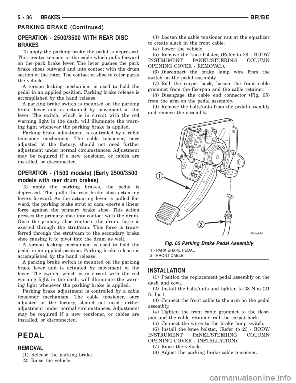
(8) Disengage the cable end connector (Fig. 65)
from the arm on the pedal assembly.
(9) Remove the bolts/nuts from the pedal assembly
and remove the assembly.
INSTALLATION
(1) Position the replacement pedal assembly on the
dash and cowl.
(2) Install the bolts/nuts and tighten to 28 N´m (21
ft. lbs.).
(3) Connect the front cable to the arm on the pedal
assembly.
(4) Tighten the front cable grommet to the floor-
pan and the cable retainer, roll the carpet back.
(5) Connect the wires to the brake lamp switch.
(6) Install the knee bolster, (Refer to 23 - BODY/
INSTRUMENT PANEL/STEERING COLUMN
OPENING COVER - INSTALLATION).
(7) Raise the vehicle.
(8) Adjust the parking brake cable tensioner.
Fig. 65 Parking Brake Pedal Assembly
1 - PARK BRAKE PEDAL
2 - FRONT CABLE
5 - 36 BRAKESBR/BE
PARKING BRAKE (Continued)
Page 314 of 2889
CLUTCH
TABLE OF CONTENTS
page page
CLUTCH
DESCRIPTION............................1
OPERATION.............................1
WARNING...............................2
DIAGNOSIS AND TESTING..................2
CLUTCH...............................2
SPECIFICATIONS.........................7
CLUTCH DISC
DESCRIPTION............................7
OPERATION.............................8
REMOVAL...............................8
INSTALLATION............................9
CLUTCH HOUSING
DIAGNOSIS AND TESTING.................11
CLUTCH HOUSING.....................11
REMOVAL..............................13
INSTALLATION...........................13
CLUTCH RELEASE BEARING
DESCRIPTION...........................14
OPERATION.............................14
REMOVAL..............................15
INSTALLATION...........................15
PRESSURE PLATE
DESCRIPTION...........................15OPERATION.............................16
FLYWHEEL
DESCRIPTION...........................16
OPERATION.............................16
DIAGNOSIS AND TESTING.................17
FLYWHEEL............................17
DISASSEMBLY...........................17
ASSEMBLY.............................17
PILOT BEARING
DESCRIPTION...........................17
OPERATION.............................18
REMOVAL..............................18
INSTALLATION...........................18
CLUTCH PEDAL
REMOVAL..............................18
INSTALLATION...........................19
LINKAGE
DESCRIPTION...........................19
OPERATION.............................20
REMOVAL..............................20
INSTALLATION...........................20
CLUTCH PEDAL POSITION SWITCH
DESCRIPTION...........................22
OPERATION.............................22
CLUTCH
DESCRIPTION
The clutch mechanism consists of a flywheel, a sin-
gle, dry-type disc, and a diaphragm style clutch cover
(Fig. 1). A hydraulic linkage is used to operate the
clutch release bearing and fork. The flywheel is
bolted to the rear flange of the crankshaft. The
clutch pressure plate is bolted to the flywheel with
the clutch disc located between these two compo-
nents. The clutch system provides the mechanical,
but still easily detachable, link between the engine
and the transmission. The system is designed to
ensure that the full torque output of the engine is
transfered to the transmission while isolating the
transmission from the engine firing pulses to mini-
mize concerns such as gear rattle.
OPERATION
Leverage, clamping force, and friction are what
make the clutch work. The disc serves as the friction
element and a diaphragm spring and pressure plate
provide the clamping force. The clutch pedal, hydrau-
lic linkage, release lever and bearing provide the
leverage.
The clutch master cylinder push rod is connected
to the clutch pedal. When the clutch pedal is
depressed, the slave cylinder is operated by the
clutch master cylinder mounted on the dash panel.
The release fork is actuated by the hydraulic slave
cylinder mounted on the transmission housing. The
release bearing is operated by a release fork pivoting
on a ball stud mounted in the transmission housing.
The release bearing then depresses the pressure
plate spring fingers, thereby releasing pressure on
the clutch disc and allowing the engine crankshaft to
spin independently of the transmission input shaft
(Fig. 2).
BR/BECLUTCH 6 - 1