2001 CHRYSLER VOYAGER HIGH BEAM SWITCH INPUT SHORT
[x] Cancel search: HIGH BEAM SWITCH INPUT SHORTPage 14 of 4284
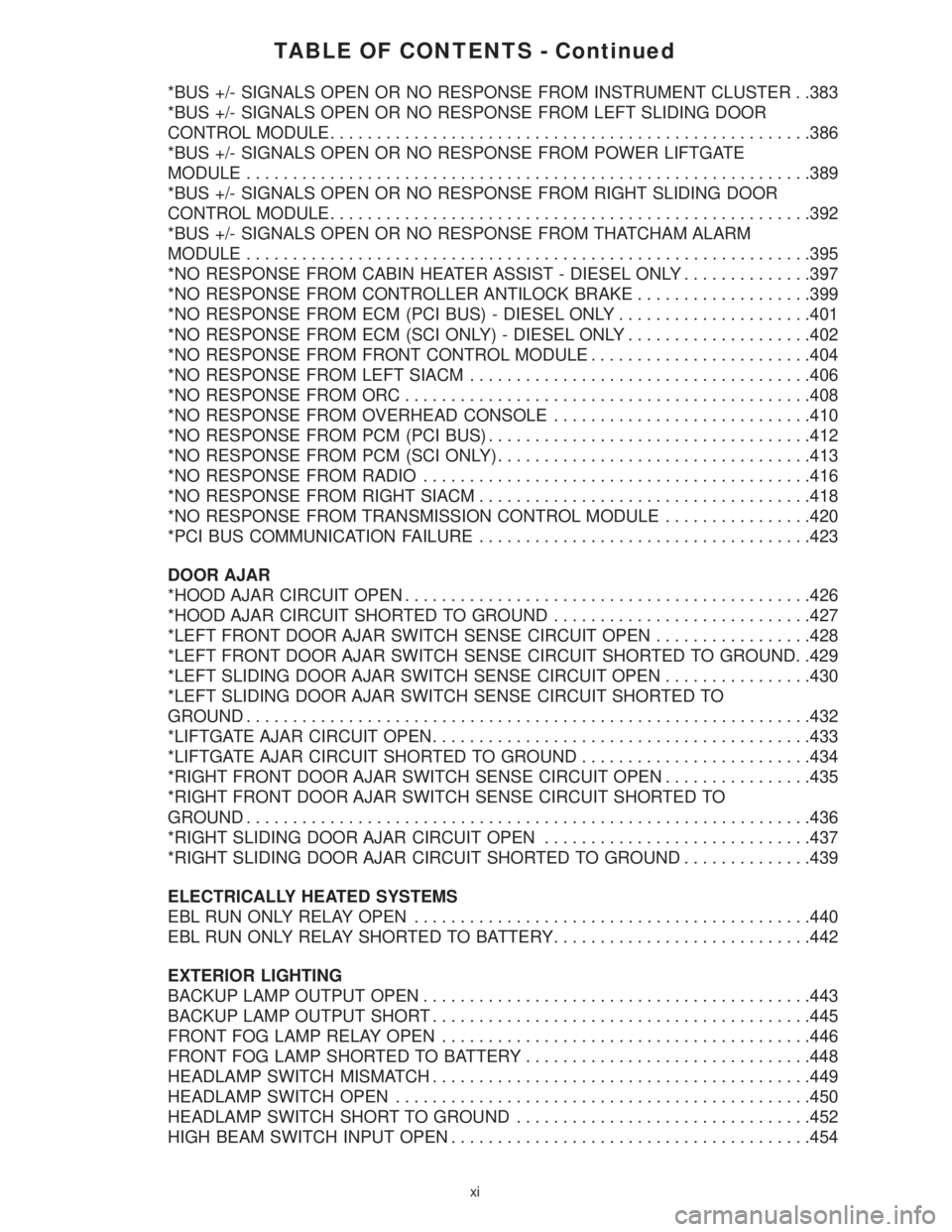
TABLE OF CONTENTS - Continued
*BUS +/- SIGNALS OPEN OR NO RESPONSE FROM INSTRUMENT CLUSTER . .383
*BUS +/- SIGNALS OPEN OR NO RESPONSE FROM LEFT SLIDING DOOR
CONTROL MODULE....................................................386
*BUS +/- SIGNALS OPEN OR NO RESPONSE FROM POWER LIFTGATE
MODULE.............................................................389
*BUS +/- SIGNALS OPEN OR NO RESPONSE FROM RIGHT SLIDING DOOR
CONTROL MODULE....................................................392
*BUS +/- SIGNALS OPEN OR NO RESPONSE FROM THATCHAM ALARM
MODULE.............................................................395
*NO RESPONSE FROM CABIN HEATER ASSIST - DIESEL ONLY..............397
*NO RESPONSE FROM CONTROLLER ANTILOCK BRAKE...................399
*NO RESPONSE FROM ECM (PCI BUS) - DIESEL ONLY.....................401
*NO RESPONSE FROM ECM (SCI ONLY) - DIESEL ONLY....................402
*NO RESPONSE FROM FRONT CONTROL MODULE........................404
*NO RESPONSE FROM LEFT SIACM.....................................406
*NO RESPONSE FROM ORC............................................408
*NO RESPONSE FROM OVERHEAD CONSOLE............................410
*NO RESPONSE FROM PCM (PCI BUS)...................................412
*NO RESPONSE FROM PCM (SCI ONLY)..................................413
*NO RESPONSE FROM RADIO..........................................416
*NO RESPONSE FROM RIGHT SIACM....................................418
*NO RESPONSE FROM TRANSMISSION CONTROL MODULE................420
*PCI BUS COMMUNICATION FAILURE....................................423
DOOR AJAR
*HOOD AJAR CIRCUIT OPEN............................................426
*HOOD AJAR CIRCUIT SHORTED TO GROUND............................427
*LEFT FRONT DOOR AJAR SWITCH SENSE CIRCUIT OPEN.................428
*LEFT FRONT DOOR AJAR SWITCH SENSE CIRCUIT SHORTED TO GROUND. .429
*LEFT SLIDING DOOR AJAR SWITCH SENSE CIRCUIT OPEN................430
*LEFT SLIDING DOOR AJAR SWITCH SENSE CIRCUIT SHORTED TO
GROUND.............................................................432
*LIFTGATE AJAR CIRCUIT OPEN.........................................433
*LIFTGATE AJAR CIRCUIT SHORTED TO GROUND.........................434
*RIGHT FRONT DOOR AJAR SWITCH SENSE CIRCUIT OPEN................435
*RIGHT FRONT DOOR AJAR SWITCH SENSE CIRCUIT SHORTED TO
GROUND.............................................................436
*RIGHT SLIDING DOOR AJAR CIRCUIT OPEN.............................437
*RIGHT SLIDING DOOR AJAR CIRCUIT SHORTED TO GROUND..............439
ELECTRICALLY HEATED SYSTEMS
EBL RUN ONLY RELAY OPEN...........................................440
EBL RUN ONLY RELAY SHORTED TO BATTERY............................442
EXTERIOR LIGHTING
BACKUP LAMP OUTPUT OPEN..........................................443
BACKUP LAMP OUTPUT SHORT.........................................445
FRONT FOG LAMP RELAY OPEN........................................446
FRONT FOG LAMP SHORTED TO BATTERY...............................448
HEADLAMP SWITCH MISMATCH.........................................449
HEADLAMP SWITCH OPEN.............................................450
HEADLAMP SWITCH SHORT TO GROUND................................452
HIGH BEAM SWITCH INPUT OPEN.......................................454
xi
Page 15 of 4284
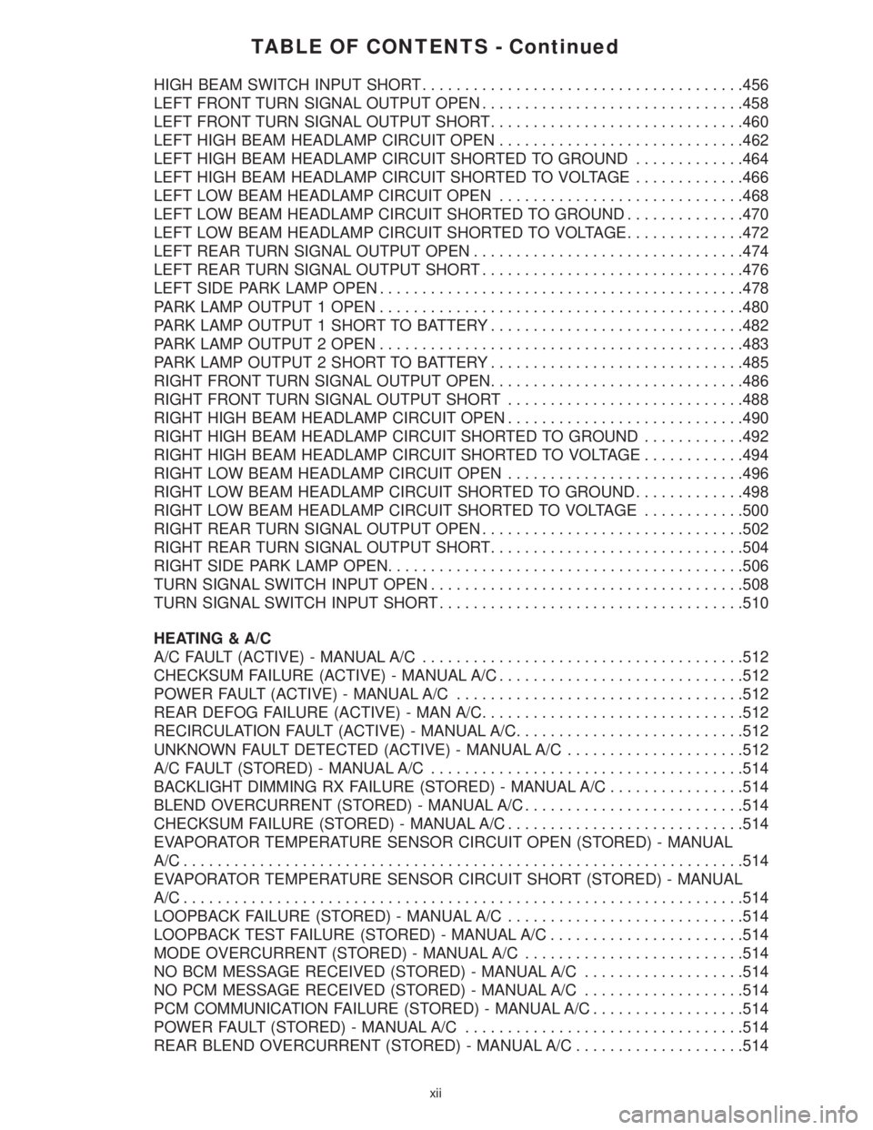
TABLE OF CONTENTS - Continued
HIGH BEAM SWITCH INPUT SHORT......................................456
LEFT FRONT TURN SIGNAL OUTPUT OPEN...............................458
LEFT FRONT TURN SIGNAL OUTPUT SHORT..............................460
LEFT HIGH BEAM HEADLAMP CIRCUIT OPEN.............................462
LEFT HIGH BEAM HEADLAMP CIRCUIT SHORTED TO GROUND.............464
LEFT HIGH BEAM HEADLAMP CIRCUIT SHORTED TO VOLTAGE.............466
LEFT LOW BEAM HEADLAMP CIRCUIT OPEN.............................468
LEFT LOW BEAM HEADLAMP CIRCUIT SHORTED TO GROUND..............470
LEFT LOW BEAM HEADLAMP CIRCUIT SHORTED TO VOLTAGE..............472
LEFT REAR TURN SIGNAL OUTPUT OPEN................................474
LEFT REAR TURN SIGNAL OUTPUT SHORT...............................476
LEFT SIDE PARK LAMP OPEN...........................................478
PARK LAMP OUTPUT 1 OPEN...........................................480
PARK LAMP OUTPUT 1 SHORT TO BATTERY..............................482
PARK LAMP OUTPUT 2 OPEN...........................................483
PARK LAMP OUTPUT 2 SHORT TO BATTERY..............................485
RIGHT FRONT TURN SIGNAL OUTPUT OPEN..............................486
RIGHT FRONT TURN SIGNAL OUTPUT SHORT............................488
RIGHT HIGH BEAM HEADLAMP CIRCUIT OPEN............................490
RIGHT HIGH BEAM HEADLAMP CIRCUIT SHORTED TO GROUND............492
RIGHT HIGH BEAM HEADLAMP CIRCUIT SHORTED TO VOLTAGE............494
RIGHT LOW BEAM HEADLAMP CIRCUIT OPEN............................496
RIGHT LOW BEAM HEADLAMP CIRCUIT SHORTED TO GROUND.............498
RIGHT LOW BEAM HEADLAMP CIRCUIT SHORTED TO VOLTAGE............500
RIGHT REAR TURN SIGNAL OUTPUT OPEN...............................502
RIGHT REAR TURN SIGNAL OUTPUT SHORT..............................504
RIGHT SIDE PARK LAMP OPEN..........................................506
TURN SIGNAL SWITCH INPUT OPEN.....................................508
TURN SIGNAL SWITCH INPUT SHORT....................................510
HEATING & A/C
A/C FAULT (ACTIVE) - MANUAL A/C......................................512
CHECKSUM FAILURE (ACTIVE) - MANUAL A/C.............................512
POWER FAULT (ACTIVE) - MANUAL A/C..................................512
REAR DEFOG FAILURE (ACTIVE) - MAN A/C...............................512
RECIRCULATION FAULT (ACTIVE) - MANUAL A/C...........................512
UNKNOWN FAULT DETECTED (ACTIVE) - MANUAL A/C.....................512
A/C FAULT (STORED) - MANUAL A/C.....................................514
BACKLIGHT DIMMING RX FAILURE (STORED) - MANUAL A/C................514
BLEND OVERCURRENT (STORED) - MANUAL A/C..........................514
CHECKSUM FAILURE (STORED) - MANUAL A/C............................514
EVAPORATOR TEMPERATURE SENSOR CIRCUIT OPEN (STORED) - MANUAL
A/C..................................................................514
EVAPORATOR TEMPERATURE SENSOR CIRCUIT SHORT (STORED) - MANUAL
A/C..................................................................514
LOOPBACK FAILURE (STORED) - MANUAL A/C............................514
LOOPBACK TEST FAILURE (STORED) - MANUAL A/C.......................514
MODE OVERCURRENT (STORED) - MANUAL A/C..........................514
NO BCM MESSAGE RECEIVED (STORED) - MANUAL A/C...................514
NO PCM MESSAGE RECEIVED (STORED) - MANUAL A/C...................514
PCM COMMUNICATION FAILURE (STORED) - MANUAL A/C..................514
POWER FAULT (STORED) - MANUAL A/C.................................514
REAR BLEND OVERCURRENT (STORED) - MANUAL A/C....................514
xii
Page 41 of 4284
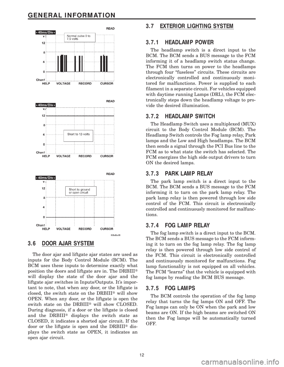
3.6 DOOR AJAR SYSTEM
The door ajar and liftgate ajar states are used as
inputs for the Body Control Module (BCM). The
BCM uses these inputs to determine exactly what
position the doors and liftgate are in. The DRBIIIt
will display the state of the door ajar and the
liftgate ajar switches in Inputs/Outputs. It's impor-
tant to note, that when any door, or the liftgate is
closed, the switch state on the DRBIIItwill show
OPEN. When any door, or the liftgate is open the
switch state on the DRBIIItwill show CLOSED.
During diagnosis, if a door or the liftgate is closed
and the DRBIIItdisplays the switch state as
CLOSED, it indicates a shorted ajar circuit. If the
door or the liftgate is open and the DRBIIItdis-
plays the switch state as OPEN, it indicates an
open ajar circuit.
3.7 EXTERIOR LIGHTING SYSTEM
3.7.1 HEADLAMP POWER
The headlamp switch is a direct input to the
BCM. The BCM sends a BUS message to the FCM
informing it of a headlamp switch status change.
The FCM then turns on power to the headlamps
through four ªfuselessº circuits. These circuits are
electronically controlled and continuously moni-
tored for malfunctions. Power is supplied to each
filament in a separate circuit. For vehicles equipped
with daytime running Lamps (DRL), the FCM elec-
tronically steps down the headlamp voltage to pro-
vide the desired illumination.
3.7.2 HEADLAMP SWITCH
The Headlamp Switch uses a multiplexed (MUX)
circuit to the Body Control Module (BCM). The
Headlamp Switch controls the Fog lamp relay, Park
lamps and the Low and High headlamps. The BCM
then sends a signal through the PCI Bus line to the
FCM as to what state the switch has selected. The
FCM energizes the high side output drivers to turn
ON the desired lamps.
3.7.3 PARK LAMP RELAY
The park lamp switch is a direct input to the
BCM. The BCM sends a BUS message to the FCM
informing it to turn on the park lamp relay. The
park lamp relay is then powered through low side
control of the FCM. This circuit is electronically
controlled and continuously monitored for malfunc-
tions.
3.7.4 FOG LAMP RELAY
The fog lamp switch is a direct input to the BCM.
The BCM sends a BUS message to the FCM inform-
ing it to turn on the fog lamp relay. The fog lamp
relay is then powered through low side control of
the FCM. This circuit is electronically controlled
and continuously monitored for malfunctions. Fog
lamp functionality is not equipped on all vehicles.
The FCM ªlearnsº that the vehicle is equipped with
fog lamps by reading the BCM BUS message.
3.7.5 FOG LAMPS
The BCM controls the operation of the fog lamp
relay that turns the fog lamps ON and OFF. The
Fog lamps can only be ON when the park and low
beams are ON. If the high beams are switched ON
then the Fog lamps will be automatically turned
OFF.
12
GENERAL INFORMATION
Page 485 of 4284
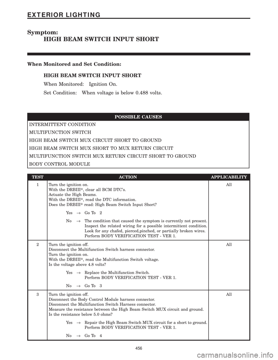
Symptom:
HIGH BEAM SWITCH INPUT SHORT
When Monitored and Set Condition:
HIGH BEAM SWITCH INPUT SHORT
When Monitored: Ignition On.
Set Condition: When voltage is below 0.488 volts.
POSSIBLE CAUSES
INTERMITTENT CONDITION
MULTIFUNCTION SWITCH
HIGH BEAM SWITCH MUX CIRCUIT SHORT TO GROUND
HIGH BEAM SWITCH MUX SHORT TO MUX RETURN CIRCUIT
MULTIFUNCTION SWITCH MUX RETURN CIRCUIT SHORT TO GROUND
BODY CONTROL MODULE
TEST ACTION APPLICABILITY
1 Turn the ignition on.
With the DRBIIIt, clear all BCM DTC's.
Actuate the High Beams.
With the DRBIIIt, read the DTC information.
Does the DRBIIItread: High Beam Switch Input Short?All
Ye s®Go To 2
No®The condition that caused the symptom is currently not present.
Inspect the related wiring for a possible intermittent condition.
Look for any chafed, pierced,pinched, or partially broken wires.
Perform BODY VERIFICATION TEST - VER 1.
2 Turn the ignition off.
Disconnect the Multifunction Switch harness connector.
Turn the ignition on.
With the DRBIIIt, read the Multifunction Switch voltage.
Is the voltage above 4.8 volts?All
Ye s®Replace the Multifunction Switch.
Perform BODY VERIFICATION TEST - VER 1.
No®Go To 3
3 Turn the ignition off.
Disconnect the Body Control Module harness connector.
Disconnect the Multifunction Switch Harness connector.
Measure the resistance between the High Beam Switch MUX circuit and ground.
Is the resistance below 5.0 ohms?All
Ye s®Repair the High Beam Switch MUX circuit for a short to ground.
Perform BODY VERIFICATION TEST - VER 1.
No®Go To 4
456
EXTERIOR LIGHTING
Page 486 of 4284
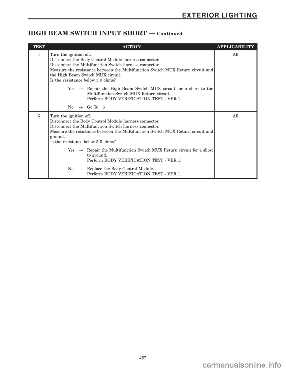
TEST ACTION APPLICABILITY
4 Turn the ignition off.
Disconnect the Body Control Module harness connector.
Disconnect the Multifunction Switch harness connector.
Measure the resistance between the Multifunction Switch MUX Return circuit and
the High Beam Switch MUX circuit.
Is the resistance below 5.0 ohms?All
Ye s®Repair the High Beam Switch MUX circuit for a short to the
Multifunction Switch MUX Return circuit.
Perform BODY VERIFICATION TEST - VER 1.
No®Go To 5
5 Turn the ignition off.
Disconnect the Body Control Module harness connector.
Disconnect the Multifunction Switch harness connector.
Measure the resistance between the Multifunction Switch MUX Return circuit and
ground.
Is the resistance below 5.0 ohms?All
Ye s®Repair the Multifunction Switch MUX Return circuit for a short
to ground.
Perform BODY VERIFICATION TEST - VER 1.
No®Replace the Body Control Module.
Perform BODY VERIFICATION TEST - VER 1.
457
EXTERIOR LIGHTING
HIGH BEAM SWITCH INPUT SHORT ÐContinued
Page 988 of 4284
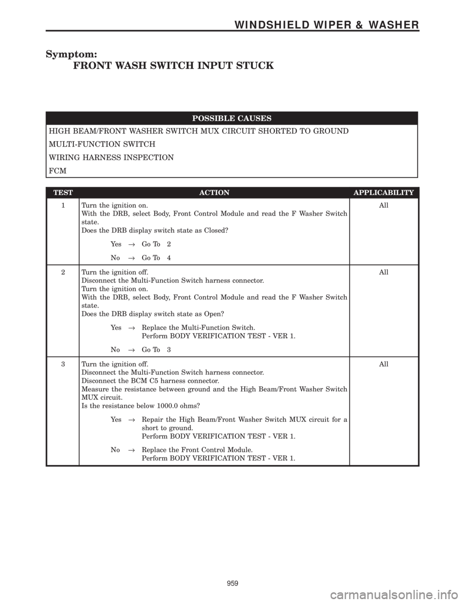
Symptom:
FRONT WASH SWITCH INPUT STUCK
POSSIBLE CAUSES
HIGH BEAM/FRONT WASHER SWITCH MUX CIRCUIT SHORTED TO GROUND
MULTI-FUNCTION SWITCH
WIRING HARNESS INSPECTION
FCM
TEST ACTION APPLICABILITY
1 Turn the ignition on.
With the DRB, select Body, Front Control Module and read the F Washer Switch
state.
Does the DRB display switch state as Closed?All
Ye s®Go To 2
No®Go To 4
2 Turn the ignition off.
Disconnect the Multi-Function Switch harness connector.
Turn the ignition on.
With the DRB, select Body, Front Control Module and read the F Washer Switch
state.
Does the DRB display switch state as Open?All
Ye s®Replace the Multi-Function Switch.
Perform BODY VERIFICATION TEST - VER 1.
No®Go To 3
3 Turn the ignition off.
Disconnect the Multi-Function Switch harness connector.
Disconnect the BCM C5 harness connector.
Measure the resistance between ground and the High Beam/Front Washer Switch
MUX circuit.
Is the resistance below 1000.0 ohms?All
Ye s®Repair the High Beam/Front Washer Switch MUX circuit for a
short to ground.
Perform BODY VERIFICATION TEST - VER 1.
No®Replace the Front Control Module.
Perform BODY VERIFICATION TEST - VER 1.
959
WINDSHIELD WIPER & WASHER
Page 1943 of 4284
DAYTIME RUNNING LAMPS
Power is reduced using pulse-width modulation to
the high beams, where by the power is switched on
and off rapidly instead of remaining on continuously.
The duration and interval of the power pulses is pro-
grammed into the Front Control Module (FCM).
HEADLAMP SYSTEM
The headlamp system will default to headlamps
ON position when ignition switch is ON and when an
open or short circuit failure occurs on the headlamp
switch input. The system will return to normal oper-
ation when the open or short is repaired. A fault will
be reported by the BCM when a failure occurs on the
dimmer or headlamp switch input.
If the exterior lamps are ON and the headlamp
switch is in any position other than OFF or AUTO
and with the ignition switch OFF (LOCK) after 3
minutes the BCM sends a message via J1850 to the
FCM informing the FCM to turn off the headlamps,
park lamps and fog lamps. This feature prevents the
vehicle battery from being discharged when the vehi-
cle lights have been left ON.
HEADLAMP TIME DELAY SYSTEM
The headlamp time delay system is activated by
turning the headlamps ON (high or low beam) while
the engine is running, turning the ignition switch
OFF, and then turning the headlamp switch OFF
within 45 seconds. The system will not activate if
more than 45 seconds elapse between ignition switch
OFF and headlamp switch OFF. The BCM will allow
the headlamps to remain ON for 90 seconds (config-
urable) before they automatically turn off (If the key
is in the ignition during the headlamp time delay
mode, then both the headlamps and park lamps
(including panel dimming) will be ON). Refer to the
Owner's Manual for more information.
If the headlamp switch is in the Auto Headlamp
Position, the headlamps are ON due to the night sig-
nal from the CMTC and the ignition switch is in any
position other than run/start, the BCM shall enter a
90 second (configurable) Auto Headlamps time delay
mode. If the key is in the ignition during the head-
lamp time delay mode, then both the headlamps and
park lamps (including panel dimming) will be ON. If
the key is not in the ignition, then only the head-
lamps will be ON. The BCM will allow the head-
lamps to remain ON for 90 seconds before they
automatically turn OFF. Refer to the Owner's Man-
ual for more information.
LAMP OUTAGE
If one or more of the following lamps (Low and/or
High beams) are out, then a ªlamps outº indicator
located in the cluster will illuminate.
OPTICAL HORN/HIGH BEAMS
When the multifunction switch is pulled to the first
detent (optical horn) signal, the headlamps are ON,
key-in the ignition the BCM shall send a message via
J1850 to the FCM to turn on the headlamps drivers
to illuminate all four filaments (Low and High
beams). When the multifunction switch is pulled to
the second detent (high beam) signal and the head-
lamps are ON, the BCM shall send a message via
J1850 to the FCM to turn on the headlamps drivers.
The High Beams are illuminated and the Low Beams
and Fog Lamps (if ON) are extinguished. If the head-
lamps were in the high beam configuration when
power was removed from the headlamps, the head-
lamps will be configured as low beam the next time
they are activated.
DIAGNOSIS AND TESTING
WARNING: EYE PROTECTION SHOULD BE USED
WHEN SERVICING GLASS COMPONENTS. PER-
SONAL INJURY CAN RESULT.
CAUTION: Do not touch the glass of halogen bulbs
with fingers or other possibly oily surface, reduced
bulb life will result. Do not use bulbs other than
those indicated in the Bulb Application table. Dam-
age to lamp and/or Daytime Running Lamp Module
can result. Do not use fuses, circuit breakers or
relays having greater amperage value than indi-
cated on the fuse panel or in the Owners Manual.
When a vehicle experiences problems with the
headlamp system, verify the condition of the battery
connections, fuses, charging system, headlamp bulbs,
wire connectors, relay, high beam switch, dimmer
switch, and headlamp switch. Refer to the appropri-
ate wiring information. The wiring information
includes wiring diagrams, proper wire and connector
repair procedures, details of wire harness routing
and retention, connector pin-out information and
location views for the various wire harness connec-
tors, splices and grounds.
Each vehicle is equipped with various lamp assem-
blies. A good ground is necessary for proper lighting
operation. Grounding is provided by the lamp socket
when it comes in contact with the metal body, or
through a separate ground wire.
When changing lamp bulbs check the socket for
corrosion. If corrosion is present, clean it with a wire
brush.
When it is necessary to remove components to ser-
vice another, it should not be necessary to apply
excessive force or bend a component to remove it.
Before damaging a trim component, verify hidden
fasteners or captured edges are not holding the com-
ponent in place.
RSLAMPS/LIGHTING - EXTERIOR8L-3
LAMPS/LIGHTING - EXTERIOR (Continued)