2001 CHRYSLER VOYAGER remote control
[x] Cancel search: remote controlPage 247 of 4284

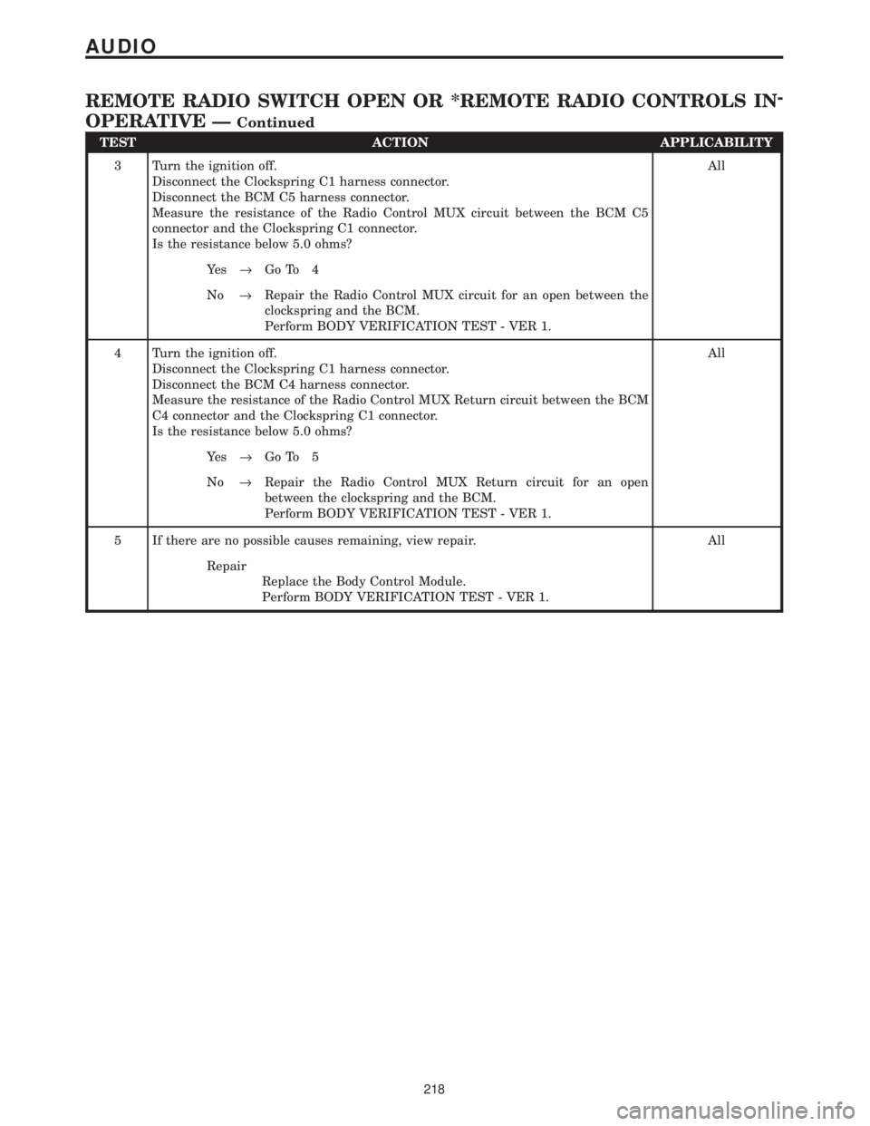
TEST ACTION APPLICABILITY
3 Turn the ignition off.
Disconnect the Clockspring C1 harness connector.
Disconnect the BCM C5 harness connector.
Measure the resistance of the Radio Control MUX circuit between the BCM C5
connector and the Clockspring C1 connector.
Is the resistance below 5.0 ohms?All
Ye s®Go To 4
No®Repair the Radio Control MUX circuit for an open between the
clockspring and the BCM.
Perform BODY VERIFICATION TEST - VER 1.
4 Turn the ignition off.
Disconnect the Clockspring C1 harness connector.
Disconnect the BCM C4 harness connector.
Measure the resistance of the Radio Control MUX Return circuit between the BCM
C4 connector and the Clockspring C1 connector.
Is the resistance below 5.0 ohms?All
Ye s®Go To 5
No®Repair the Radio Control MUX Return circuit for an open
between the clockspring and the BCM.
Perform BODY VERIFICATION TEST - VER 1.
5 If there are no possible causes remaining, view repair. All
Repair
Replace the Body Control Module.
Perform BODY VERIFICATION TEST - VER 1.
218
AUDIO
REMOTE RADIO SWITCH OPEN OR *REMOTE RADIO CONTROLS IN-
OPERATIVE Ð
Continued
Page 248 of 4284

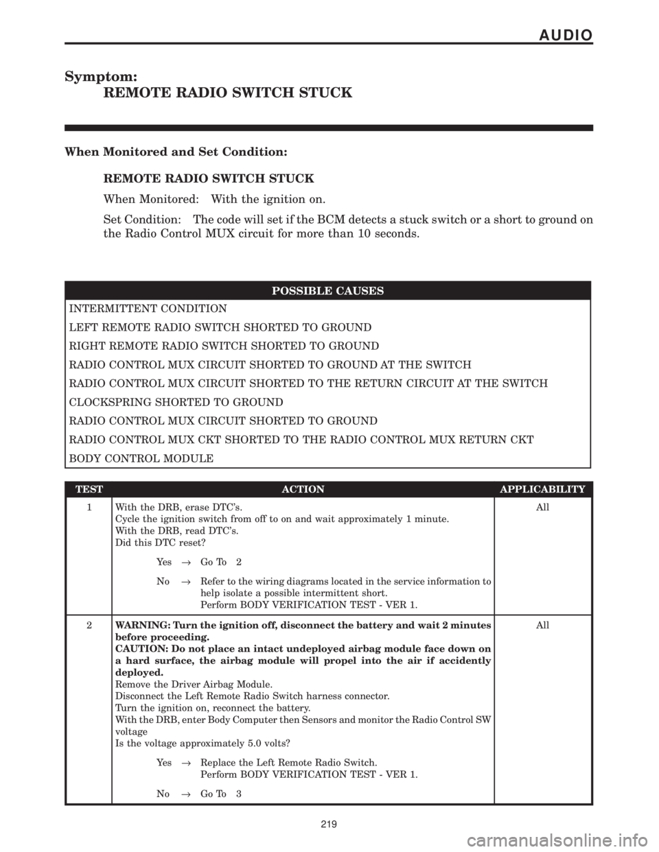
Symptom:
REMOTE RADIO SWITCH STUCK
When Monitored and Set Condition:
REMOTE RADIO SWITCH STUCK
When Monitored: With the ignition on.
Set Condition: The code will set if the BCM detects a stuck switch or a short to ground on
the Radio Control MUX circuit for more than 10 seconds.
POSSIBLE CAUSES
INTERMITTENT CONDITION
LEFT REMOTE RADIO SWITCH SHORTED TO GROUND
RIGHT REMOTE RADIO SWITCH SHORTED TO GROUND
RADIO CONTROL MUX CIRCUIT SHORTED TO GROUND AT THE SWITCH
RADIO CONTROL MUX CIRCUIT SHORTED TO THE RETURN CIRCUIT AT THE SWITCH
CLOCKSPRING SHORTED TO GROUND
RADIO CONTROL MUX CIRCUIT SHORTED TO GROUND
RADIO CONTROL MUX CKT SHORTED TO THE RADIO CONTROL MUX RETURN CKT
BODY CONTROL MODULE
TEST ACTION APPLICABILITY
1 With the DRB, erase DTC's.
Cycle the ignition switch from off to on and wait approximately 1 minute.
With the DRB, read DTC's.
Did this DTC reset?All
Ye s®Go To 2
No®Refer to the wiring diagrams located in the service information to
help isolate a possible intermittent short.
Perform BODY VERIFICATION TEST - VER 1.
2WARNING: Turn the ignition off, disconnect the battery and wait 2 minutes
before proceeding.
CAUTION: Do not place an intact undeployed airbag module face down on
a hard surface, the airbag module will propel into the air if accidently
deployed.
Remove the Driver Airbag Module.
Disconnect the Left Remote Radio Switch harness connector.
Turn the ignition on, reconnect the battery.
With the DRB, enter Body Computer then Sensors and monitor the Radio Control SW
voltage
Is the voltage approximately 5.0 volts?All
Ye s®Replace the Left Remote Radio Switch.
Perform BODY VERIFICATION TEST - VER 1.
No®Go To 3
219
AUDIO
Page 249 of 4284

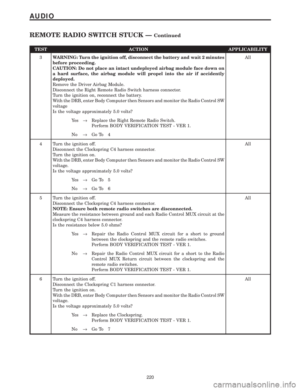
TEST ACTION APPLICABILITY
3WARNING: Turn the ignition off, disconnect the battery and wait 2 minutes
before proceeding.
CAUTION: Do not place an intact undeployed airbag module face down on
a hard surface, the airbag module will propel into the air if accidently
deployed.
Remove the Driver Airbag Module.
Disconnect the Right Remote Radio Switch harness connector.
Turn the ignition on, reconnect the battery.
With the DRB, enter Body Computer then Sensors and monitor the Radio Control SW
voltage
Is the voltage approximately 5.0 volts?All
Ye s®Replace the Right Remote Radio Switch.
Perform BODY VERIFICATION TEST - VER 1.
No®Go To 4
4 Turn the ignition off.
Disconnect the Clockspring C4 harness connector.
Turn the ignition on.
With the DRB, enter Body Computer then Sensors and monitor the Radio Control SW
voltage.
Is the voltage approximately 5.0 volts?All
Ye s®Go To 5
No®Go To 6
5 Turn the ignition off.
Disconnect the Clockspring C4 harness connector.
NOTE: Ensure both remote radio switches are disconnected.
Measure the resistance between ground and each Radio Control MUX circuit at the
clockspring C4 harness connector.
Is the resistance below 5.0 ohms?All
Ye s®Repair the Radio Control MUX circuit for a short to ground
between the clockspring and the remote radio switches.
Perform BODY VERIFICATION TEST - VER 1.
No®Repair the Radio Control MUX circuit for a short to the Radio
Control MUX Return circuit between the clockspring and the
remote radio switches.
Perform BODY VERIFICATION TEST - VER 1.
6 Turn the ignition off.
Disconnect the Clockspring C1 harness connector.
Turn the ignition on.
With the DRB, enter Body Computer then Sensors and monitor the Radio Control SW
voltage.
Is the voltage approximately 5.0 volts?All
Ye s®Replace the Clockspring.
Perform BODY VERIFICATION TEST - VER 1.
No®Go To 7
220
AUDIO
REMOTE RADIO SWITCH STUCK ÐContinued
Page 250 of 4284

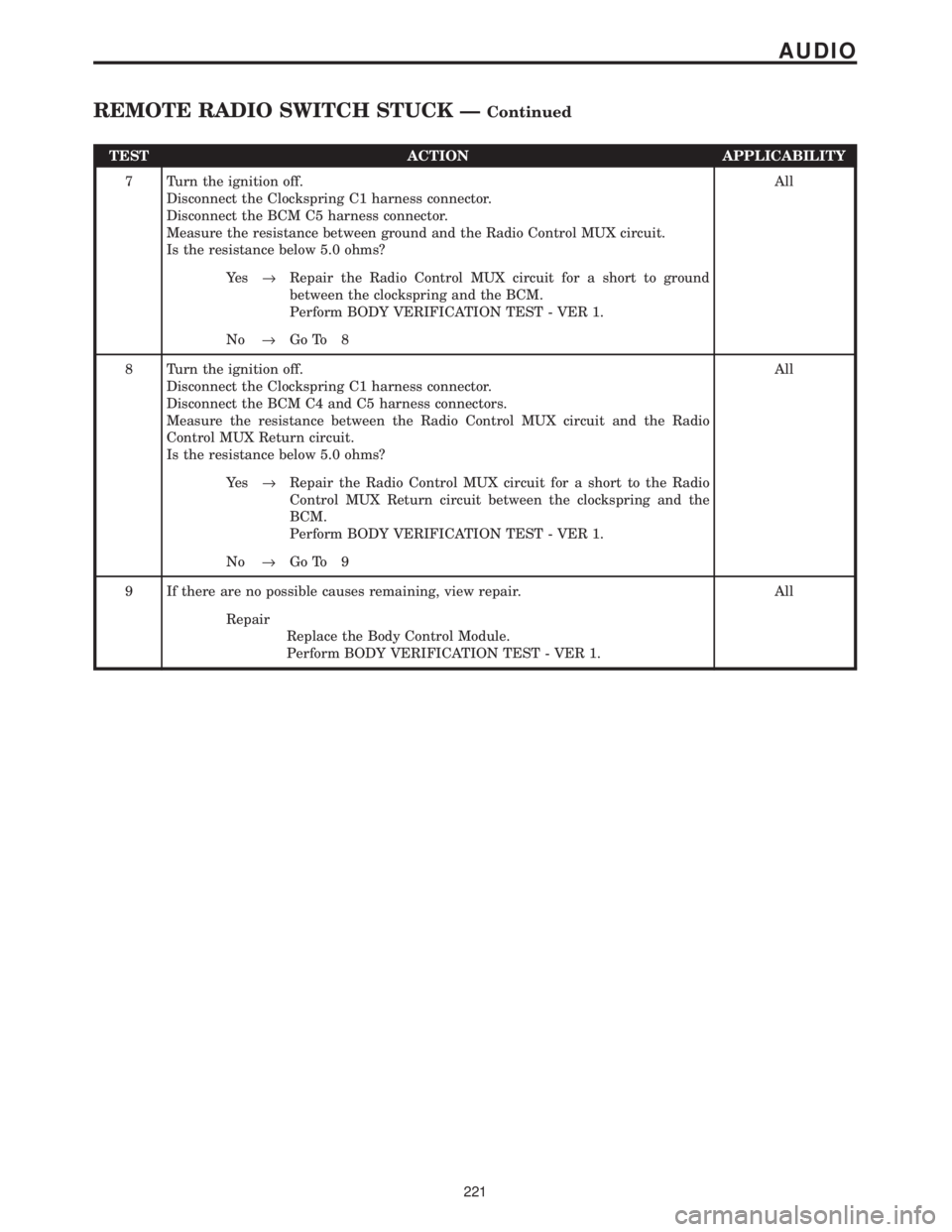
TEST ACTION APPLICABILITY
7 Turn the ignition off.
Disconnect the Clockspring C1 harness connector.
Disconnect the BCM C5 harness connector.
Measure the resistance between ground and the Radio Control MUX circuit.
Is the resistance below 5.0 ohms?All
Ye s®Repair the Radio Control MUX circuit for a short to ground
between the clockspring and the BCM.
Perform BODY VERIFICATION TEST - VER 1.
No®Go To 8
8 Turn the ignition off.
Disconnect the Clockspring C1 harness connector.
Disconnect the BCM C4 and C5 harness connectors.
Measure the resistance between the Radio Control MUX circuit and the Radio
Control MUX Return circuit.
Is the resistance below 5.0 ohms?All
Ye s®Repair the Radio Control MUX circuit for a short to the Radio
Control MUX Return circuit between the clockspring and the
BCM.
Perform BODY VERIFICATION TEST - VER 1.
No®Go To 9
9 If there are no possible causes remaining, view repair. All
Repair
Replace the Body Control Module.
Perform BODY VERIFICATION TEST - VER 1.
221
AUDIO
REMOTE RADIO SWITCH STUCK ÐContinued
Page 274 of 4284

Symptom List:
FRONT IR SENSOR AND CONTROL HEAD MISMATCH (ACTIVE)
FRONT IR SENSOR CHANGE TOO LARGE (ACTIVE)
FRONT IR SENSOR HIGH (ACTIVE)
FRONT IR SENSOR LOW (ACTIVE)
Test Note: All symptoms listed above are diagnosed using the same tests.
The title for the tests will be FRONT IR SENSOR AND
CONTROL HEAD MISMATCH (ACTIVE).
When Monitored and Set Condition:
FRONT IR SENSOR AND CONTROL HEAD MISMATCH (ACTIVE)
When Monitored: Every 8 seconds with the ignition on.
Set Condition: This condition is set if the ATC does not receive the intake air temperature
response message within 8 seconds.
FRONT IR SENSOR HIGH (ACTIVE)
When Monitored: With the ignition on and the IOD fuse installed.
Set Condition: This DTC is set if the ATC reads the Front IR Sensor value and it is above
250 A/D counts.
FRONT IR SENSOR LOW (ACTIVE)
When Monitored: With the ignition on and the IOD fuse installed.
Set Condition: This DTC is set if the ATC reads the Front IR Sensor value and it is below
5 A/D counts.
POSSIBLE CAUSES
ATC REMOTE SENSOR
TEST ACTION APPLICABILITY
1 This DTC indicates a fault in the ATC Remote Sensor.
View repair.All
Repair
Replace the ATC Remote Sensor.
With the DRBIIIt, reset the ATC after repair/replacement is
complete.
Perform BODY VERIFICATION TEST - VER 1.
245
AUTOMATIC TEMPERATURE CONTROL
Page 275 of 4284

Symptom List:
FRONT IR SENSOR NOT CALIBRATED (ACTIVE)
FRONT KEYBOARD FAULT (ACTIVE)
Test Note: All symptoms listed above are diagnosed using the same tests.
The title for the tests will be FRONT IR SENSOR NOT
CALIBRATED (ACTIVE).
When Monitored and Set Condition:
FRONT IR SENSOR NOT CALIBRATED (ACTIVE)
When Monitored: With the ignition on and the IOD fuse installed.
Set Condition: This DTC is set if the ATC cannot read the IR sensor values or the IR
sensor values are not within a defined range of the HVAC air door motor counts.
POSSIBLE CAUSES
ATC - PROTECTED IGNITION CIRCUIT FAULT
KDB 2 CLOCK CIRCUIT SHORTED TO VOLTAGE
KDB 2 DATA CIRCUIT SHORTED TO GROUND
KDB 2 DATA CIRCUIT SHORTED TO VOLTAGE
PROTECTED IGNITION CIRCUIT OPEN
SENSOR RETURN CIRCUIT OPEN
KDB 2 CLOCK CIRCUIT SHORTED TO GROUND
KDB 2 DATA CIRCUIT OPEN
ATC - KDB 2 DATA CIRCUIT FAULT
ATC - SENSOR RETURN CIRCUIT FAULT
KDB 2 CLOCK CIRCUIT OPEN
ATC - KDB 2 CLOCK CIRCUIT FAULT
ATC REMOTE SENSOR
TEST ACTION APPLICABILITY
1 Turn the ignition off.
Disconnect the ATC Remote Sensor harness connector.
Turn the ignition on.
Measure the voltage of the Protected Ignition circuit.
Is the voltage above 10.0 volts?All
Ye s®Go To 2
No®Go To 16
246
AUTOMATIC TEMPERATURE CONTROL
Page 276 of 4284

TEST ACTION APPLICABILITY
2 Turn the ignition off.
Disconnect the ATC Remote Sensor harness connector.
Turn the ignition on.
Measure the voltage of the KDB 2 Data circuit.
Is the voltage above 10.0 volts?All
Ye s®Go To 3
No®Go To 13
3 Turn the ignition off.
Disconnect the ATC Remote Sensor harness connector.
Disconnect the ATC C3 harness connector.
Turn the ignition on.
Measure the voltage of the KDB 2 Data circuit.
Is the voltage above 1.0 volt?All
Ye s®Repair the KDB 2 Data circuit for a short to voltage.
With the DRBIIIt, reset the ATC after repair/replacement is
complete.
Perform BODY VERIFICATION TEST - VER 1.
No®Go To 4
4 Turn the ignition off.
Disconnect the ATC Remote Sensor harness connector.
Use Scope input cable CH7058, Cable to Probe adapter CH7062, and the red and
black test probes.
Connect the scope input cable to the channel one connector on the DRB. Attach the
red and black leads and the cable to probe adapter to the scope input cable.
Select Lab Scope.
Select Live.
Select 12 volt square wave.
Press F2 for Scope.
Press F2 and use the arrows to set the voltage range to 20 volts, the Offset to 4.0, and
the Probe to x10. Press F2 again and set the divisions to 40ms/Div, then press F2
again when complete.
Connect the Black lead to the chassis ground. Connect the Red lead to the KDB 2
Clock circuit in the ATC Remote Sensor harness connector.
Turn the ignition on.
Observe the voltage display on the DRB Lab Scope.
NOTE: The lab scope pattern should look similar to the example given in the
support material and cycle from approximately 0 volts to 8.0 volts.
Did the lab scope pattern and voltage react as noted above?All
Ye s®Go To 5
No®Go To 9
5 Turn the ignition off.
Disconnect the ATC Remote Sensor harness connector.
Measure the resistance between ground and the Sensor Return circuit.
Is the resistance below 10 ohms?All
Ye s®Go To 6
No®Go To 7
247
AUTOMATIC TEMPERATURE CONTROL
FRONT IR SENSOR NOT CALIBRATED (ACTIVE) ÐContinued
Page 277 of 4284

TEST ACTION APPLICABILITY
6 If there are no possible causes remaining, view repair. All
Repair
Replace the ATC Remote Sensor.
With the DRBIIIt, reset the ATC after repair/replacement is
complete.
Perform BODY VERIFICATION TEST - VER 1.
7 Turn the ignition off.
Disconnect the ATC Remote Sensor harness connector.
Measure the resistance of the Sensor Return circuit.
Is the resistance below 5.0 ohms?All
Ye s®Go To 8
No®Repair the Sensor Return circuit for an open.
With the DRBIIIt, reset the ATC after repair/replacement is
complete.
Perform BODY VERIFICATION TEST - VER 1.
8 If there are no possible causes remaining, view repair. All
Repair
Replace the ATC.
With the DRBIIIt, reset the ATC after repair/replacement is
complete.
Perform BODY VERIFICATION TEST - VER 1.
9 Turn the ignition off.
Disconnect the ATC Remote Sensor harness connector.
Disconnect the ATC C3 harness connector.
Turn the ignition on.
Measure the voltage of the KDB 2 Clock circuit.
Is the voltage above 1.0 volt?All
Ye s®Repair the KDB 2 Clock circuit for a short to voltage.
With the DRBIIIt, reset the ATC after repair/replacement is
complete.
Perform BODY VERIFICATION TEST - VER 1.
No®Go To 10
10 Turn the ignition off.
Disconnect the ATC Remote Sensor harness connector.
Disconnect the ATC C3 harness connector.
Measure the resistance between ground and the KDB 2 Clock circuit.
Is the resistance above 100k ohms?All
Ye s®Go To 11
No®Repair the KDB 2 Clock circuit for a short to ground.
With the DRBIIIt, reset the ATC after repair/replacement is
complete.
Perform BODY VERIFICATION TEST - VER 1.
248
AUTOMATIC TEMPERATURE CONTROL
FRONT IR SENSOR NOT CALIBRATED (ACTIVE) ÐContinued