2001 CHRYSLER VOYAGER seat memory
[x] Cancel search: seat memoryPage 1088 of 4284

MEMORY SEAT REAR VERTICAL MOTOR - RED 2 WAYCAV CIRCUIT FUNCTION
1 P111 14LG/YL DRIVER SEAT REAR UP DRIVER
2 P113 14LG/WT DRIVER SEAT REAR DOWN DRIVER
MEMORY SEAT REAR VERTICAL POSITION SENSOR - BLACK 3 WAYCAV CIRCUIT FUNCTION
A P28 20LG/BR DRIVER SEAT POSITION SENSOR GROUND
B P27 20LG/LB REAR RISER POSITION SIGNAL
C P29 20LG/WT DRIVER SEAT SENSOR 5 VOLT SUPPLY
MEMORY SEAT RECLINER MOTOR - GREEN 2 WAYCAV CIRCUIT FUNCTION
1 P141 14LG/BR DRIVER SEAT RECLINER UP DRIVER
2 P143 14LG/GY DRIVER SEAT RECLINER DOWN DRIVER
MEMORY SEAT RECLINER POSITION SENSOR - BLACK 3 WAYCAV CIRCUIT FUNCTION
A P29 20LG/WT DRIVER SEAT SENSOR 5 VOLT SUPPLY
B P47 20LG/LB RECLINER POSITION SIGNAL
C P28 20LG/BR DRIVER SEAT POSITION SENSOR GROUND
MEMORY SEAT SWITCH - BLACK 2 WAYCAV CIRCUIT FUNCTION
1 G200 20VT/BR MEMORY SEAT SET SWITCH MUX
2 G920 20VT/YL MEMORY SEAT SWITCH RETURN
C
O
N
N
E
C
T
O
R
P
I
N
O
U
T
S
1059
CONNECTOR PINOUTS
Page 1089 of 4284
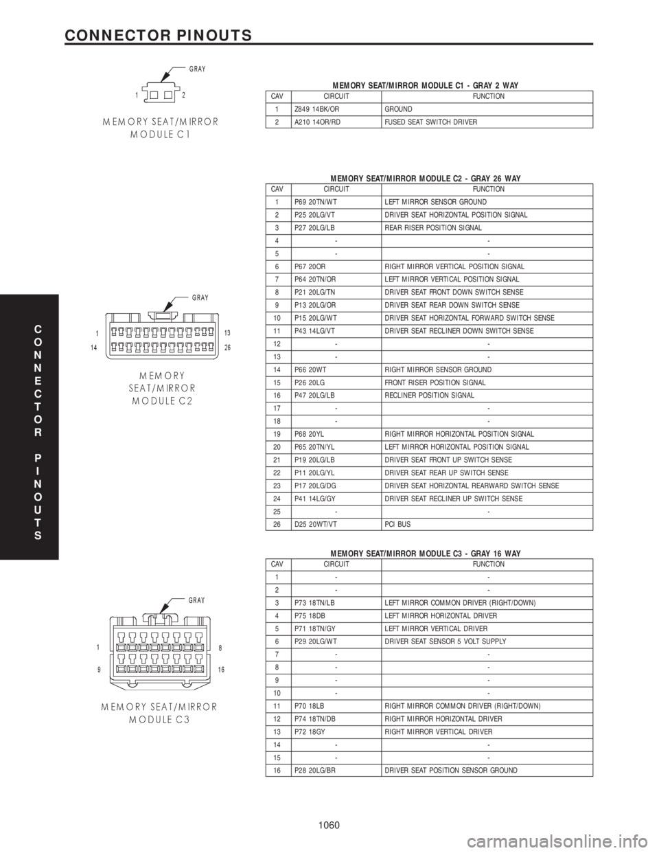
MEMORY SEAT/MIRROR MODULE C1 - GRAY 2 WAYCAV CIRCUIT FUNCTION
1 Z849 14BK/OR GROUND
2 A210 14OR/RD FUSED SEAT SWITCH DRIVER
MEMORY SEAT/MIRROR MODULE C2 - GRAY 26 WAYCAV CIRCUIT FUNCTION
1 P69 20TN/WT LEFT MIRROR SENSOR GROUND
2 P25 20LG/VT DRIVER SEAT HORIZONTAL POSITION SIGNAL
3 P27 20LG/LB REAR RISER POSITION SIGNAL
4- -
5- -
6 P67 20OR RIGHT MIRROR VERTICAL POSITION SIGNAL
7 P64 20TN/OR LEFT MIRROR VERTICAL POSITION SIGNAL
8 P21 20LG/TN DRIVER SEAT FRONT DOWN SWITCH SENSE
9 P13 20LG/OR DRIVER SEAT REAR DOWN SWITCH SENSE
10 P15 20LG/WT DRIVER SEAT HORIZONTAL FORWARD SWITCH SENSE
11 P43 14LG/VT DRIVER SEAT RECLINER DOWN SWITCH SENSE
12 - -
13 - -
14 P66 20WT RIGHT MIRROR SENSOR GROUND
15 P26 20LG FRONT RISER POSITION SIGNAL
16 P47 20LG/LB RECLINER POSITION SIGNAL
17 - -
18 - -
19 P68 20YL RIGHT MIRROR HORIZONTAL POSITION SIGNAL
20 P65 20TN/YL LEFT MIRROR HORIZONTAL POSITION SIGNAL
21 P19 20LG/LB DRIVER SEAT FRONT UP SWITCH SENSE
22 P11 20LG/YL DRIVER SEAT REAR UP SWITCH SENSE
23 P17 20LG/DG DRIVER SEAT HORIZONTAL REARWARD SWITCH SENSE
24 P41 14LG/GY DRIVER SEAT RECLINER UP SWITCH SENSE
25 - -
26 D25 20WT/VT PCI BUS
MEMORY SEAT/MIRROR MODULE C3 - GRAY 16 WAYCAV CIRCUIT FUNCTION
1- -
2- -
3 P73 18TN/LB LEFT MIRROR COMMON DRIVER (RIGHT/DOWN)
4 P75 18DB LEFT MIRROR HORIZONTAL DRIVER
5 P71 18TN/GY LEFT MIRROR VERTICAL DRIVER
6 P29 20LG/WT DRIVER SEAT SENSOR 5 VOLT SUPPLY
7- -
8- -
9- -
10 - -
11 P70 18LB RIGHT MIRROR COMMON DRIVER (RIGHT/DOWN)
12 P74 18TN/DB RIGHT MIRROR HORIZONTAL DRIVER
13 P72 18GY RIGHT MIRROR VERTICAL DRIVER
14 - -
15 - -
16 P28 20LG/BR DRIVER SEAT POSITION SENSOR GROUND
C
O
N
N
E
C
T
O
R
P
I
N
O
U
T
S
1060
CONNECTOR PINOUTS
Page 1090 of 4284
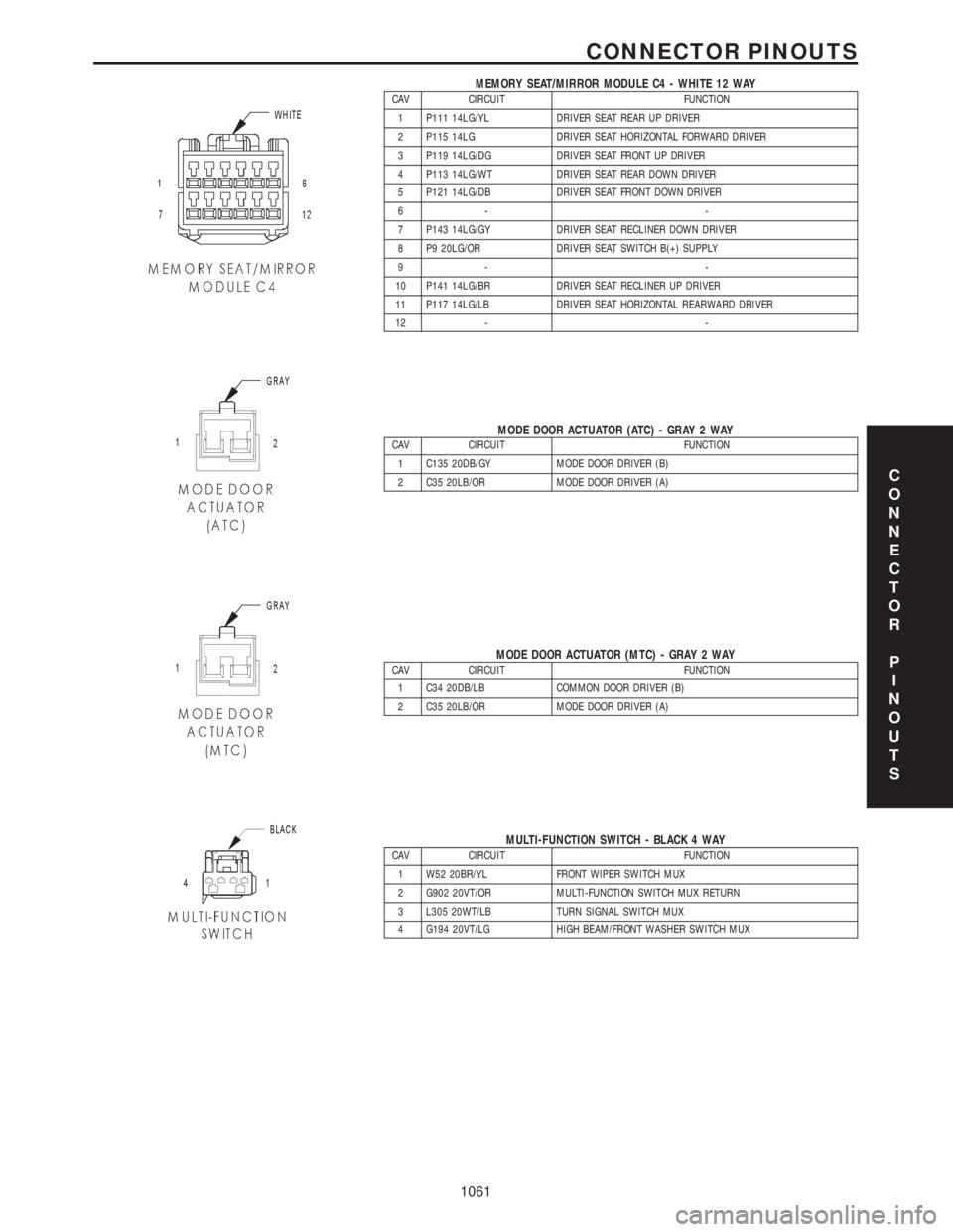
MEMORY SEAT/MIRROR MODULE C4 - WHITE 12 WAYCAV CIRCUIT FUNCTION
1 P111 14LG/YL DRIVER SEAT REAR UP DRIVER
2 P115 14LG DRIVER SEAT HORIZONTAL FORWARD DRIVER
3 P119 14LG/DG DRIVER SEAT FRONT UP DRIVER
4 P113 14LG/WT DRIVER SEAT REAR DOWN DRIVER
5 P121 14LG/DB DRIVER SEAT FRONT DOWN DRIVER
6- -
7 P143 14LG/GY DRIVER SEAT RECLINER DOWN DRIVER
8 P9 20LG/OR DRIVER SEAT SWITCH B(+) SUPPLY
9- -
10 P141 14LG/BR DRIVER SEAT RECLINER UP DRIVER
11 P117 14LG/LB DRIVER SEAT HORIZONTAL REARWARD DRIVER
12 - -
MODE DOOR ACTUATOR (ATC) - GRAY 2 WAYCAV CIRCUIT FUNCTION
1 C135 20DB/GY MODE DOOR DRIVER (B)
2 C35 20LB/OR MODE DOOR DRIVER (A)
MODE DOOR ACTUATOR (MTC) - GRAY 2 WAYCAV CIRCUIT FUNCTION
1 C34 20DB/LB COMMON DOOR DRIVER (B)
2 C35 20LB/OR MODE DOOR DRIVER (A)
MULTI-FUNCTION SWITCH - BLACK 4 WAYCAV CIRCUIT FUNCTION
1 W52 20BR/YL FRONT WIPER SWITCH MUX
2 G902 20VT/OR MULTI-FUNCTION SWITCH MUX RETURN
3 L305 20WT/LB TURN SIGNAL SWITCH MUX
4 G194 20VT/LG HIGH BEAM/FRONT WASHER SWITCH MUX
C
O
N
N
E
C
T
O
R
P
I
N
O
U
T
S
1061
CONNECTOR PINOUTS
Page 1205 of 4284
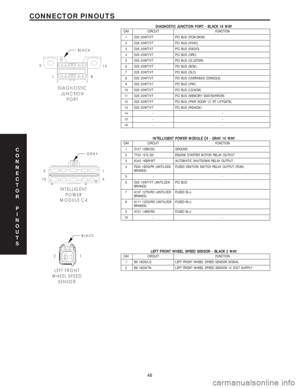
DIAGNOSTIC JUNCTION PORT - BLACK 16 WAYCAV CIRCUIT FUNCTION
1 D25 20WT/VT PCI BUS (PCM/SKIM)
2 D25 20WT/VT PCI BUS (HVAC)
3 D25 20WT/VT PCI BUS (RADIO)
4 D25 20WT/VT PCI BUS (ORC)
5 D25 20WT/VT PCI BUS (CLUSTER)
6 D25 20WT/VT PCI BUS (BCM)
7 D25 20WT/VT PCI BUS (DLC)
8 D25 20WT/VT PCI BUS (OVERHEAD CONSOLE)
9 D25 20WT/VT PCI BUS (IPM)
10 D25 20WT/VT PCI BUS (LSIACM)
11 D25 20WT/VT PCI BUS (MEMORY SEAT/MIRROR)
12 D25 20WT/VT PCI BUS (PWR DOOR/ LT, RT LIFTGATE)
13 D25 20WT/VT PCI BUS (RSIACM)
14 - -
15 - -
16 - -
INTELLIGENT POWER MODULE C4 - GRAY 10 WAYCAV CIRCUIT FUNCTION
1 Z127 12BK/DG GROUND
2 T750 12YL/GY ENGINE STARTER MOTOR RELAY OUTPUT
3 K342 16BR/WT AUTOMATIC SHUTDOWN RELAY OUTPUT
4 F500 18DG/PK (ANTILOCK
BRAKES)FUSED IGNITION SWITCH RELAY OUTPUT (RUN)
5- -
6 D25 16WT/VT (ANTILOCK
BRAKES)PCI BUS
7 A107 12TN/RD (ANTILOCK
BRAKES)FUSED B(+)
8 A111 12DG/RD (ANTILOCK
BRAKES)FUSED B(+)
9 A701 14BR/RD FUSED B(+)
10 - -
LEFT FRONT WHEEL SPEED SENSOR - BLACK 2 WAYCAV CIRCUIT FUNCTION
1 B9 18DG/LG LEFT FRONT WHEEL SPEED SENSOR SIGNAL
2 B8 18DG/TN LEFT FRONT WHEEL SPEED SENSOR 12 VOLT SUPPLY
C
O
N
N
E
C
T
O
R
P
I
N
O
U
T
S
48
CONNECTOR PINOUTS
Page 1825 of 4284
ELECTRONIC CONTROL MODULES
TABLE OF CONTENTS
page page
ELECTRONIC CONTROL MODULES
STANDARD PROCEDURE...................1
PCM/SKIM PROGRAMMING................1
BODY CONTROL MODULE
DESCRIPTION............................2
OPERATION.............................3
REMOVAL...............................3
INSTALLATION............................3
CONTROLLER ANTILOCK BRAKE
DESCRIPTION............................3
OPERATION.............................3
REMOVAL...............................4
INSTALLATION............................4
DATA LINK CONNECTOR
DESCRIPTION............................5
OPERATION.............................5
FRONT CONTROL MODULE
DESCRIPTION............................5
OPERATION.............................5
DIAGNOSIS AND TESTING..................6
FRONT CONTROL MODULE...............6
REMOVAL...............................6
INSTALLATION............................6
MEMORY HEATED SEAT/MIRROR MODULE
REMOVAL...............................7
INSTALLATION............................7
POWER LIFTGATE MODULE
DESCRIPTION............................7
OPERATION.............................7REMOVAL...............................7
INSTALLATION............................8
POWERTRAIN CONTROL MODULE
DESCRIPTION............................8
OPERATION.............................19
STANDARD PROCEDURE..................21
OBTAINING DIAGNOSTIC TROUBLE
CODES...............................21
REMOVAL..............................22
INSTALLATION...........................22
SENTRY KEY IMMOBILIZER MODULE
DESCRIPTION...........................22
OPERATION.............................23
REMOVAL..............................23
INSTALLATION...........................23
SLIDING DOOR CONTROL MODULE
DESCRIPTION...........................23
OPERATION.............................24
REMOVAL..............................24
INSTALLATION...........................24
TRANSMISSION CONTROL MODULE
DESCRIPTION...........................24
OPERATION.............................24
STANDARD PROCEDURE..................27
PINION FACTOR PROCEDURE............27
QUICK LEARN PROCEDURE..............27
TCC BREAK-IN VIEW/RESET PROCEDURE. . . 28
REMOVAL..............................28
INSTALLATION...........................29
ELECTRONIC CONTROL
MODULES
STANDARD PROCEDURE - PCM/SKIM
PROGRAMMING
NOTE: Before replacing the PCM for a failed driver,
control circuit or ground circuit, be sure to check
the related component/circuit integrity for failures
not detected due to a double fault in the circuit.
Most PCM driver/control circuit failures are caused
by internal component failures (i.e. relay and sole-
noids) and shorted circuits (i.e. pull-ups, drivers
and switched circuits). These failures are difficult to
detect when a double fault has occurred and only
one DTC has set.When a PCM (SBEC) and the SKIM are replaced
at the same time perform the following steps in
order:
(1) Program the new PCM (SBEC)
(2) Program the new SKIM
(3) Replace all ignition keys and program them to
the new SKIM.
PROGRAMMING THE PCM (SBEC)
The SKIS Secret Key is an ID code that is unique
to each SKIM. This code is programmed and stored
in the SKIM, PCM and transponder chip (ignition
keys). When replacing the PCM it is necessary to
program the secret key into the new PCM using the
DRB III. Perform the following steps to program the
secret key into the PCM.
RSELECTRONIC CONTROL MODULES8E-1
Page 1831 of 4284
MEMORY HEATED SEAT/
MIRROR MODULE
REMOVAL
(1) Disconnect and isolate the negative battery
cable.
(2) Move seat to full forward position.
(3) Working under the seat, disconnect the module
wire harness connectors.
(4) Remove the module retaining screws.
(5) Remove the module from under the seat.
INSTALLATION
(1) Install the module under the seat.
(2) Install the module retaining screws.
(3) Working under the seat, connect the module
wire harness connectors.
(4) Connect and isolate the negative battery cable.
POWER LIFTGATE MODULE
DESCRIPTION
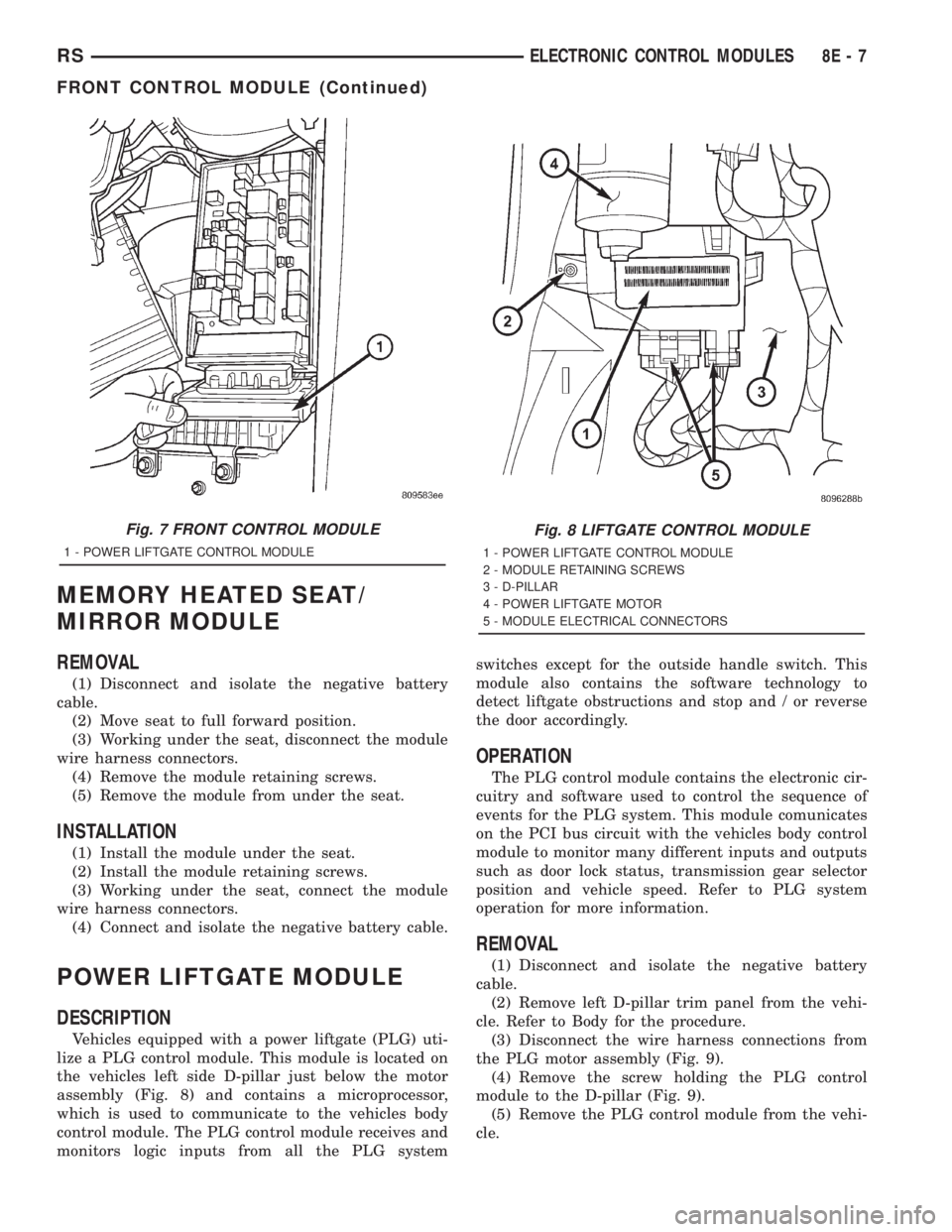
Vehicles equipped with a power liftgate (PLG) uti-
lize a PLG control module. This module is located on
the vehicles left side D-pillar just below the motor
assembly (Fig. 8) and contains a microprocessor,
which is used to communicate to the vehicles body
control module. The PLG control module receives and
monitors logic inputs from all the PLG systemswitches except for the outside handle switch. This
module also contains the software technology to
detect liftgate obstructions and stop and / or reverse
the door accordingly.
OPERATION
The PLG control module contains the electronic cir-
cuitry and software used to control the sequence of
events for the PLG system. This module comunicates
on the PCI bus circuit with the vehicles body control
module to monitor many different inputs and outputs
such as door lock status, transmission gear selector
position and vehicle speed. Refer to PLG system
operation for more information.
REMOVAL
(1) Disconnect and isolate the negative battery
cable.
(2) Remove left D-pillar trim panel from the vehi-
cle. Refer to Body for the procedure.
(3) Disconnect the wire harness connections from
the PLG motor assembly (Fig. 9).
(4) Remove the screw holding the PLG control
module to the D-pillar (Fig. 9).
(5) Remove the PLG control module from the vehi-
cle.
Fig. 7 FRONT CONTROL MODULE
1 - POWER LIFTGATE CONTROL MODULE
Fig. 8 LIFTGATE CONTROL MODULE
1 - POWER LIFTGATE CONTROL MODULE
2 - MODULE RETAINING SCREWS
3 - D-PILLAR
4 - POWER LIFTGATE MOTOR
5 - MODULE ELECTRICAL CONNECTORS
RSELECTRONIC CONTROL MODULES8E-7
FRONT CONTROL MODULE (Continued)
Page 1903 of 4284
HEATED SEAT SYSTEM
TABLE OF CONTENTS
page page
HEATED SEAT SYSTEM
DESCRIPTION............................7
OPERATION.............................8
DRIVER HEATED SEAT SWITCH
DESCRIPTION............................8
OPERATION.............................9
DIAGNOSIS AND TESTING..................9
HEATED SEAT SWITCH...................9
REMOVAL..............................10
INSTALLATION...........................10
HEATED SEAT ELEMENT
DESCRIPTION...........................10
OPERATION.............................11DIAGNOSIS AND TESTING.................11
HEATED SEAT ELEMENT.................11
HEATED SEAT SENSOR
DESCRIPTION...........................11
DIAGNOSIS AND TESTING.................11
HEATED SEAT SENSOR..................11
PASSENGER HEATED SEAT SWITCH
DESCRIPTION...........................11
OPERATION.............................11
DIAGNOSIS AND TESTING.................12
HEATED SEAT SWITCH..................12
REMOVAL..............................13
INSTALLATION...........................13
HEATED SEAT SYSTEM
DESCRIPTION
Individually controlled driver and passenger side
electrically heated front seats are available factory-
installed optional equipment on this model, when it
is also equipped with the power seat option. The
heated seat system allows both the driver and the
front seat passenger the option to select one of twoseat heating ranges, Low or High, or to turn the indi-
vidual seat heaters Off using the heated seat
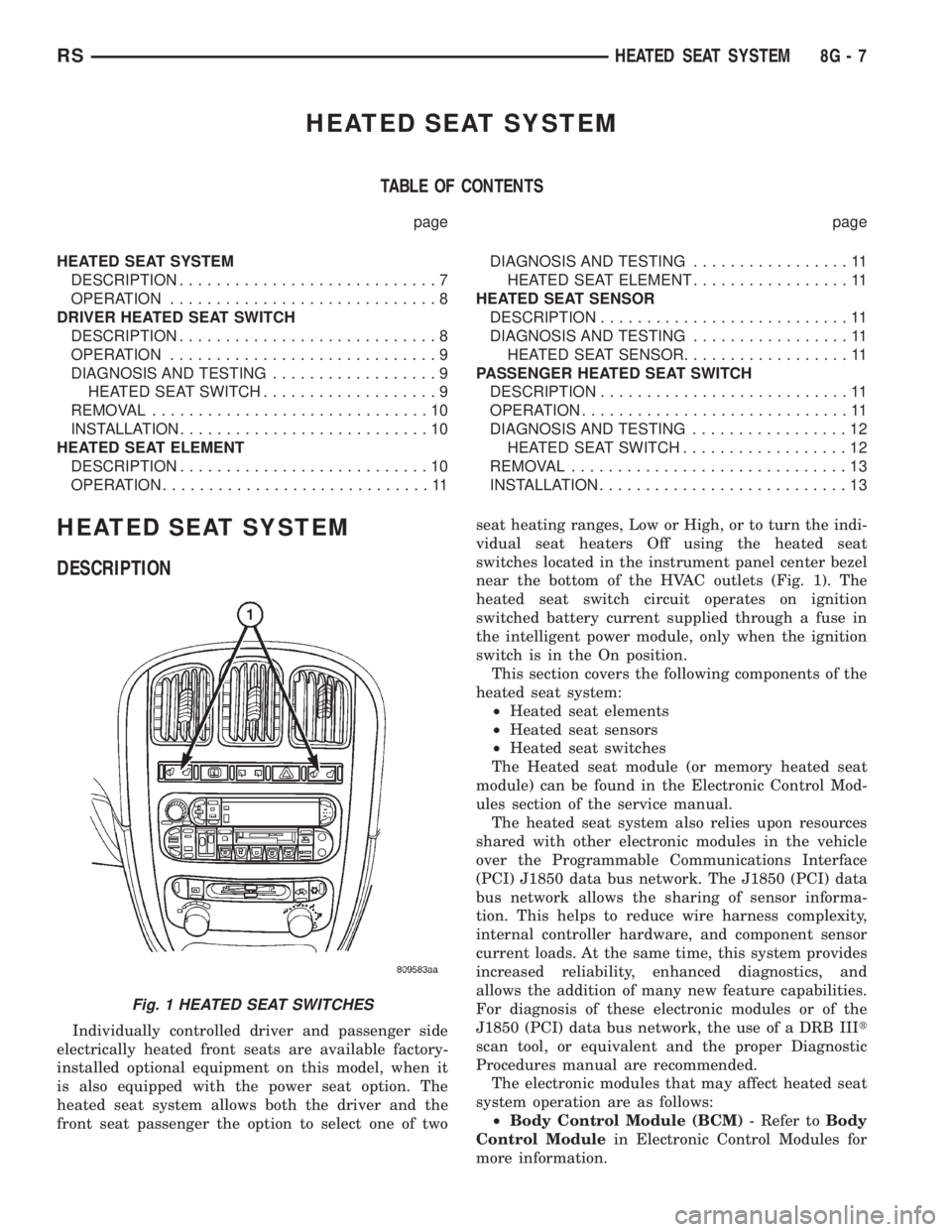
switches located in the instrument panel center bezel
near the bottom of the HVAC outlets (Fig. 1). The
heated seat switch circuit operates on ignition
switched battery current supplied through a fuse in
the intelligent power module, only when the ignition
switch is in the On position.
This section covers the following components of the
heated seat system:
²Heated seat elements
²Heated seat sensors
²Heated seat switches
The Heated seat module (or memory heated seat
module) can be found in the Electronic Control Mod-
ules section of the service manual.
The heated seat system also relies upon resources
shared with other electronic modules in the vehicle
over the Programmable Communications Interface
(PCI) J1850 data bus network. The J1850 (PCI) data
bus network allows the sharing of sensor informa-
tion. This helps to reduce wire harness complexity,
internal controller hardware, and component sensor
current loads. At the same time, this system provides
increased reliability, enhanced diagnostics, and
allows the addition of many new feature capabilities.
For diagnosis of these electronic modules or of the
J1850 (PCI) data bus network, the use of a DRB IIIt
scan tool, or equivalent and the proper Diagnostic
Procedures manual are recommended.
The electronic modules that may affect heated seat
system operation are as follows:
²Body Control Module (BCM)- Refer toBody
Control Modulein Electronic Control Modules for
more information.
Fig. 1 HEATED SEAT SWITCHES
RSHEATED SEAT SYSTEM8G-7
Page 1904 of 4284
²Remote Keyless Entry Module (RKE)- Refer
toRemote Keyless Entry Modulein Power Locks
for more information.
²Electronic Vehicle Information Center
(EVIC)- Refer toElectronic Vehicle Information
Centerin Overhead Console for more information.
²Heated Seat Module (HSM)- Refer toHeated
Seat Modulein Electronic Control Modules for more
information.
²Memory Heated Seat Module (MHSM)-If
the vehicle is equipped with the Memory System,
refer toMemory Seat Mirror Module (MSMM)in
Electronic Control Modules for more information.
Refer toWiring Diagramsfor complete circuit
diagrams. Following are general descriptions of the
major components in the heated seat system.
OPERATION
The heated seat system will only operate when the
ignition switch is in the On position, and the surface
temperature at the front seat heating element sen-
sors is below the designed temperature set points of
the system. The heated seat system will not operate
in ambient temperatures greater than about 41É C
(105É F). The front seat heating elements and sensors
are hard wired to the Heated Seat Module (HSM) or
the Memory Heated Seat Module (MHSM).
The heated seat switches are hard wired to the
Body Control Module (BCM). The BCM monitors the
heated seat switch inputs, then sends heated seat
switch status messages to the HSM or MHSM over
the Programmable Communications Interface J1850
(PCI) data bus. The HSM or MHSM contains the con-
trol logic for the heated seat system. The HSM or
MHSM responds to the heated seat switch status
messages, ignition switch status messages, and the
front seat heating element sensor inputs by control-
ling the output to the front seat heating elements
through integral solid-state relays.
When a seat heater is turned on, the sensor
located on the seat cushion electric heater element
provides the HSM or MHSM with an input indicating
the surface temperature of the seat cushion. If the
surface temperature input is below the temperature
set point for the selected Low or High heated seat
switch position, the HSM or MHSM energizes the
integral solid-state relay, which supplies battery cur-
rent to the heating elements in the seat cushion and
back. When the sensor input indicates the correct
temperature set point has been achieved, the HSM or
MHSM de-energizes the solid-state relay. The HSM
or MHSM will continue to cycle the solid-state relay
as needed to maintain the temperature set point.
The HSM or MHSM and the seat heater elements
operate on non-switched battery current supplied
through the power seat fuse in the intelligent powermodule. However, the HSM or MHSM will automati-
cally turn off the heating elements if it detects an
open in the sensor circuit, a short in the heating ele-
ment circuit causing an excessive current draw, or
when the ignition switch is turned to the Off posi-
tion.
See the owner's manual in the vehicle glove box for
more information on the features, use and operation
of the heated seat system.
DRIVER HEATED SEAT
SWITCH
DESCRIPTION
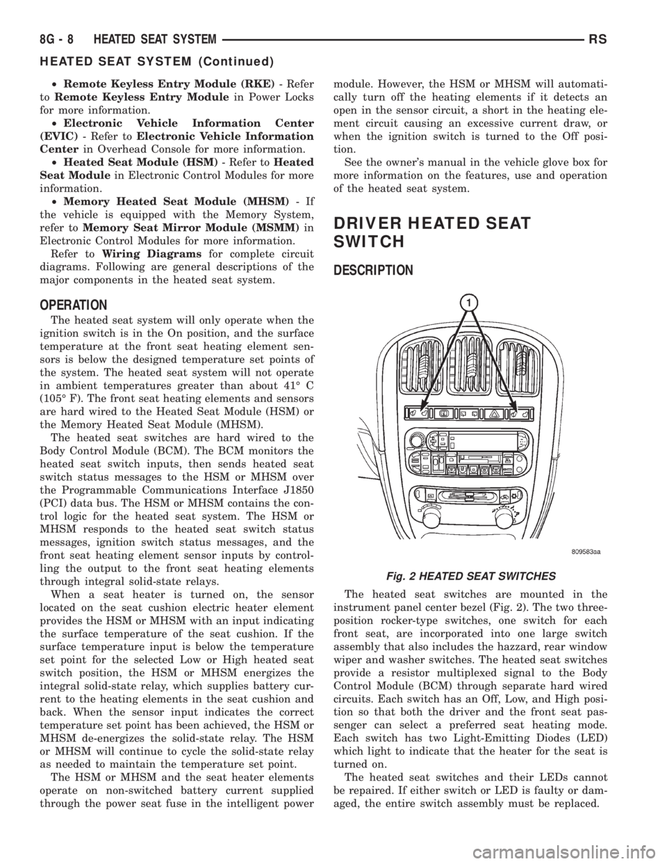
The heated seat switches are mounted in the
instrument panel center bezel (Fig. 2). The two three-
position rocker-type switches, one switch for each
front seat, are incorporated into one large switch
assembly that also includes the hazzard, rear window
wiper and washer switches. The heated seat switches
provide a resistor multiplexed signal to the Body
Control Module (BCM) through separate hard wired
circuits. Each switch has an Off, Low, and High posi-
tion so that both the driver and the front seat pas-
senger can select a preferred seat heating mode.
Each switch has two Light-Emitting Diodes (LED)
which light to indicate that the heater for the seat is
turned on.
The heated seat switches and their LEDs cannot
be repaired. If either switch or LED is faulty or dam-
aged, the entire switch assembly must be replaced.
Fig. 2 HEATED SEAT SWITCHES
8G - 8 HEATED SEAT SYSTEMRS
HEATED SEAT SYSTEM (Continued)