2001 CHRYSLER VOYAGER sensor
[x] Cancel search: sensorPage 4040 of 4284
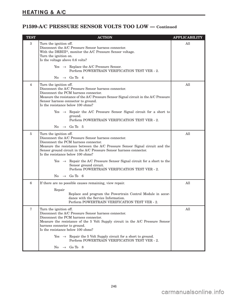
TEST ACTION APPLICABILITY
3 Turn the ignition off.
Disconnect the A/C Pressure Sensor harness connector.
With the DRBIIIt, monitor the A/C Pressure Sensor voltage.
Turn the ignition on.
Is the voltage above 0.6 volts?All
Ye s®Replace the A/C Pressure Sensor.
Perform POWERTRAIN VERIFICATION TEST VER - 2.
No®Go To 4
4 Turn the ignition off.
Disconnect the A/C Pressure Sensor harness connector.
Disconnect the PCM harness connector.
Measure the resistance of the A/C Pressure Sensor Signal circuit in the A/C Pressure
Sensor harness connector to ground.
Is the resistance below 100 ohms?All
Ye s®Repair the A/C Pressure Sensor Signal circuit for a short to
ground.
Perform POWERTRAIN VERIFICATION TEST VER - 2.
No®Go To 5
5 Turn the ignition off.
Disconnect the A/C Pressure Sensor harness connector.
Disconnect the PCM harness connector.
Measure the resistance between the A/C Pressure Sensor Signal circuit and the
Sensor ground circuit in the A/C Pressure Sensor harness connector.
Is the resistance below 100 ohms?All
Ye s®Repair the A/C Pressure Sensor Signal circuit for a short to the
Sensor ground circuit.
Perform POWERTRAIN VERIFICATION TEST VER - 2.
No®Go To 6
6 If there are no possible causes remaining, view repair. All
Repair
Replace and program the Powertrain Control Module in accor-
dance with the Service Information.
Perform POWERTRAIN VERIFICATION TEST VER - 2.
7 Turn the ignition off.
Disconnect the A/C Pressure Sensor harness connector.
Disconnect the PCM harness connector.
Measure the resistance of the 5 Volt Supply circuit in the A/C Pressure Sensor
harness connector to ground.
Is the resistance below 100 ohms?All
Ye s®Repair the 5 Volt Supply circuit for a short to ground.
Perform POWERTRAIN VERIFICATION TEST VER - 2.
No®Go To 8
246
HEATING & A/C
P1599-A/C PRESSURE SENSOR VOLTS TOO LOW ÐContinued
Page 4041 of 4284
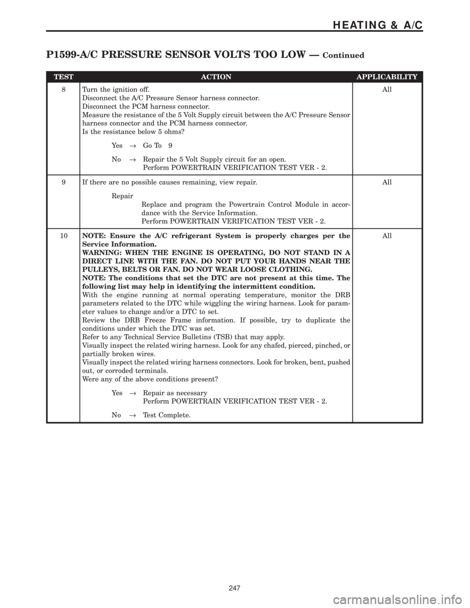
TEST ACTION APPLICABILITY
8 Turn the ignition off.
Disconnect the A/C Pressure Sensor harness connector.
Disconnect the PCM harness connector.
Measure the resistance of the 5 Volt Supply circuit between the A/C Pressure Sensor
harness connector and the PCM harness connector.
Is the resistance below 5 ohms?All
Ye s®Go To 9
No®Repair the 5 Volt Supply circuit for an open.
Perform POWERTRAIN VERIFICATION TEST VER - 2.
9 If there are no possible causes remaining, view repair. All
Repair
Replace and program the Powertrain Control Module in accor-
dance with the Service Information.
Perform POWERTRAIN VERIFICATION TEST VER - 2.
10NOTE: Ensure the A/C refrigerant System is properly charges per the
Service Information.
WARNING: WHEN THE ENGINE IS OPERATING, DO NOT STAND IN A
DIRECT LINE WITH THE FAN. DO NOT PUT YOUR HANDS NEAR THE
PULLEYS, BELTS OR FAN. DO NOT WEAR LOOSE CLOTHING.
NOTE: The conditions that set the DTC are not present at this time. The
following list may help in identifying the intermittent condition.
With the engine running at normal operating temperature, monitor the DRB
parameters related to the DTC while wiggling the wiring harness. Look for param-
eter values to change and/or a DTC to set.
Review the DRB Freeze Frame information. If possible, try to duplicate the
conditions under which the DTC was set.
Refer to any Technical Service Bulletins (TSB) that may apply.
Visually inspect the related wiring harness. Look for any chafed, pierced, pinched, or
partially broken wires.
Visually inspect the related wiring harness connectors. Look for broken, bent, pushed
out, or corroded terminals.
Were any of the above conditions present?All
Ye s®Repair as necessary
Perform POWERTRAIN VERIFICATION TEST VER - 2.
No®Test Complete.
247
HEATING & A/C
P1599-A/C PRESSURE SENSOR VOLTS TOO LOW ÐContinued
Page 4052 of 4284
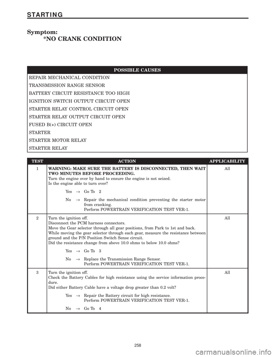
Symptom:
*NO CRANK CONDITION
POSSIBLE CAUSES
REPAIR MECHANICAL CONDITION
TRANSMISSION RANGE SENSOR
BATTERY CIRCUIT RESISTANCE TOO HIGH
IGNITION SWITCH OUTPUT CIRCUIT OPEN
STARTER RELAY CONTROL CIRCUIT OPEN
STARTER RELAY OUTPUT CIRCUIT OPEN
FUSED B(+) CIRCUIT OPEN
STARTER
STARTER MOTOR RELAY
STARTER RELAY
TEST ACTION APPLICABILITY
1WARNING: MAKE SURE THE BATTERY IS DISCONNECTED, THEN WAIT
TWO MINUTES BEFORE PROCEEDING.
Turn the engine over by hand to ensure the engine is not seized.
Is the engine able to turn over?All
Ye s®Go To 2
No®Repair the mechanical condition preventing the starter motor
from cranking.
Perform POWERTRAIN VERIFICATION TEST VER-1.
2 Turn the ignition off.
Disconnect the PCM harness connectors.
Move the Gear selector through all gear positions, from Park to 1st and back.
While moving the gear selector through each gear, measure the resistance between
ground and the P/N Position Switch Sense circuit.
Did the resistance change from above 10.0 ohms to below 10.0 ohms?All
Ye s®Go To 3
No®Replace the Transmission Range Sensor.
Perform POWERTRAIN VERIFICATION TEST VER-1.
3 Turn the ignition off.
Check the Battery Cables for high resistance using the service information proce-
dure.
Did either Battery Cable have a voltage drop greater than 0.2 volt?All
Ye s®Repair the Battery circuit for high resistance.
Perform POWERTRAIN VERIFICATION TEST VER-1.
No®Go To 4
258
STARTING
Page 4056 of 4284
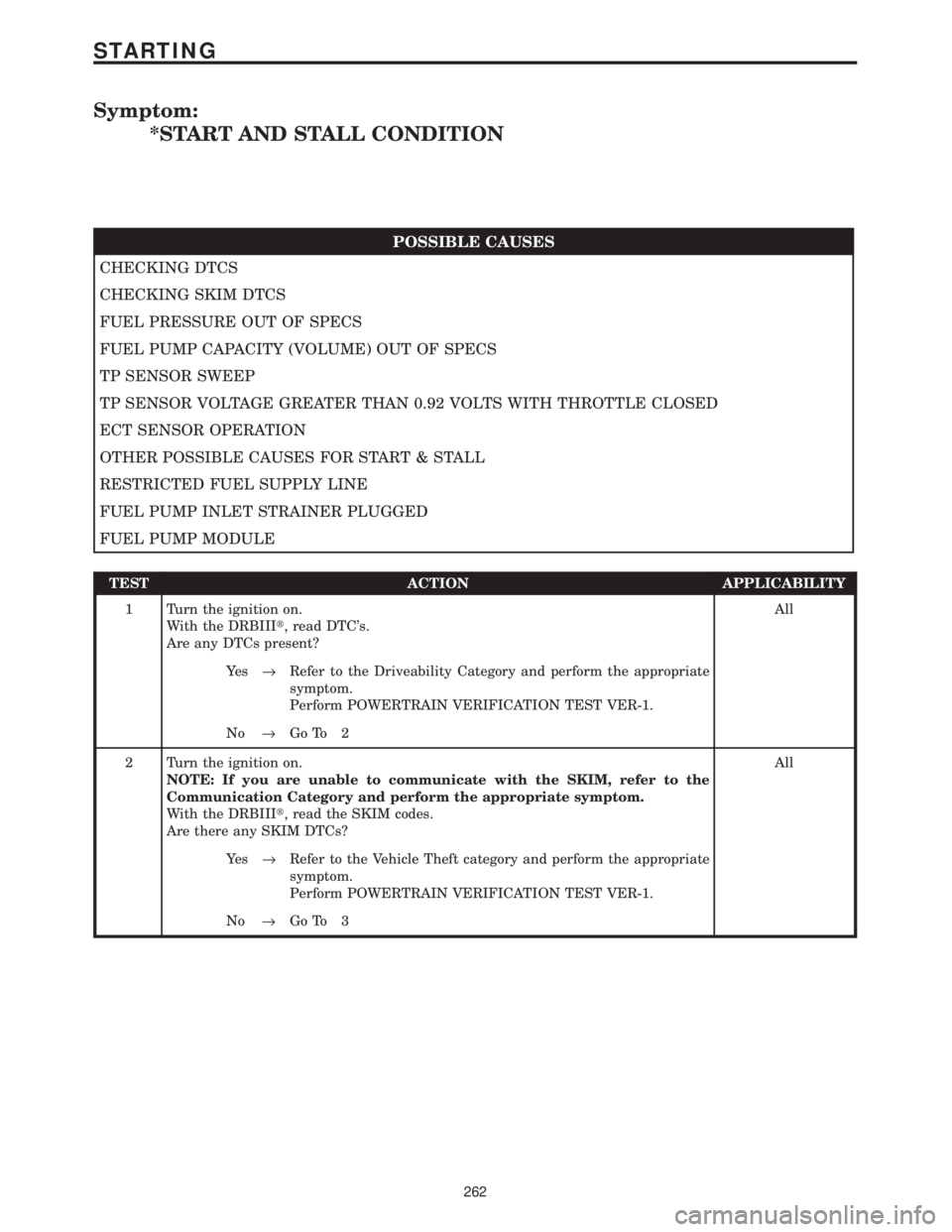
Symptom:
*START AND STALL CONDITION
POSSIBLE CAUSES
CHECKING DTCS
CHECKING SKIM DTCS
FUEL PRESSURE OUT OF SPECS
FUEL PUMP CAPACITY (VOLUME) OUT OF SPECS
TP SENSOR SWEEP
TP SENSOR VOLTAGE GREATER THAN 0.92 VOLTS WITH THROTTLE CLOSED
ECT SENSOR OPERATION
OTHER POSSIBLE CAUSES FOR START & STALL
RESTRICTED FUEL SUPPLY LINE
FUEL PUMP INLET STRAINER PLUGGED
FUEL PUMP MODULE
TEST ACTION APPLICABILITY
1 Turn the ignition on.
With the DRBIIIt, read DTC's.
Are any DTCs present?All
Ye s®Refer to the Driveability Category and perform the appropriate
symptom.
Perform POWERTRAIN VERIFICATION TEST VER-1.
No®Go To 2
2 Turn the ignition on.
NOTE: If you are unable to communicate with the SKIM, refer to the
Communication Category and perform the appropriate symptom.
With the DRBIIIt, read the SKIM codes.
Are there any SKIM DTCs?All
Ye s®Refer to the Vehicle Theft category and perform the appropriate
symptom.
Perform POWERTRAIN VERIFICATION TEST VER-1.
No®Go To 3
262
STARTING
Page 4058 of 4284
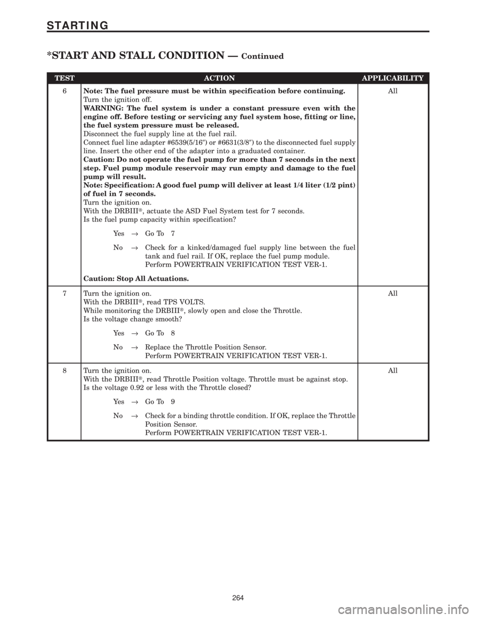
TEST ACTION APPLICABILITY
6Note: The fuel pressure must be within specification before continuing.
Turn the ignition off.
WARNING: The fuel system is under a constant pressure even with the
engine off. Before testing or servicing any fuel system hose, fitting or line,
the fuel system pressure must be released.
Disconnect the fuel supply line at the fuel rail.
Connect fuel line adapter #6539(5/169) or #6631(3/89) to the disconnected fuel supply
line. Insert the other end of the adapter into a graduated container.
Caution: Do not operate the fuel pump for more than 7 seconds in the next
step. Fuel pump module reservoir may run empty and damage to the fuel
pump will result.
Note: Specification: A good fuel pump will deliver at least 1/4 liter (1/2 pint)
of fuel in 7 seconds.
Turn the ignition on.
With the DRBIIIt, actuate the ASD Fuel System test for 7 seconds.
Is the fuel pump capacity within specification?All
Ye s®Go To 7
No®Check for a kinked/damaged fuel supply line between the fuel
tank and fuel rail. If OK, replace the fuel pump module.
Perform POWERTRAIN VERIFICATION TEST VER-1.
Caution: Stop All Actuations.
7 Turn the ignition on.
With the DRBIIIt, read TPS VOLTS.
While monitoring the DRBIIIt, slowly open and close the Throttle.
Is the voltage change smooth?All
Ye s®Go To 8
No®Replace the Throttle Position Sensor.
Perform POWERTRAIN VERIFICATION TEST VER-1.
8 Turn the ignition on.
With the DRBIIIt, read Throttle Position voltage. Throttle must be against stop.
Is the voltage 0.92 or less with the Throttle closed?All
Ye s®Go To 9
No®Check for a binding throttle condition. If OK, replace the Throttle
Position Sensor.
Perform POWERTRAIN VERIFICATION TEST VER-1.
264
STARTING
*START AND STALL CONDITION ÐContinued
Page 4059 of 4284
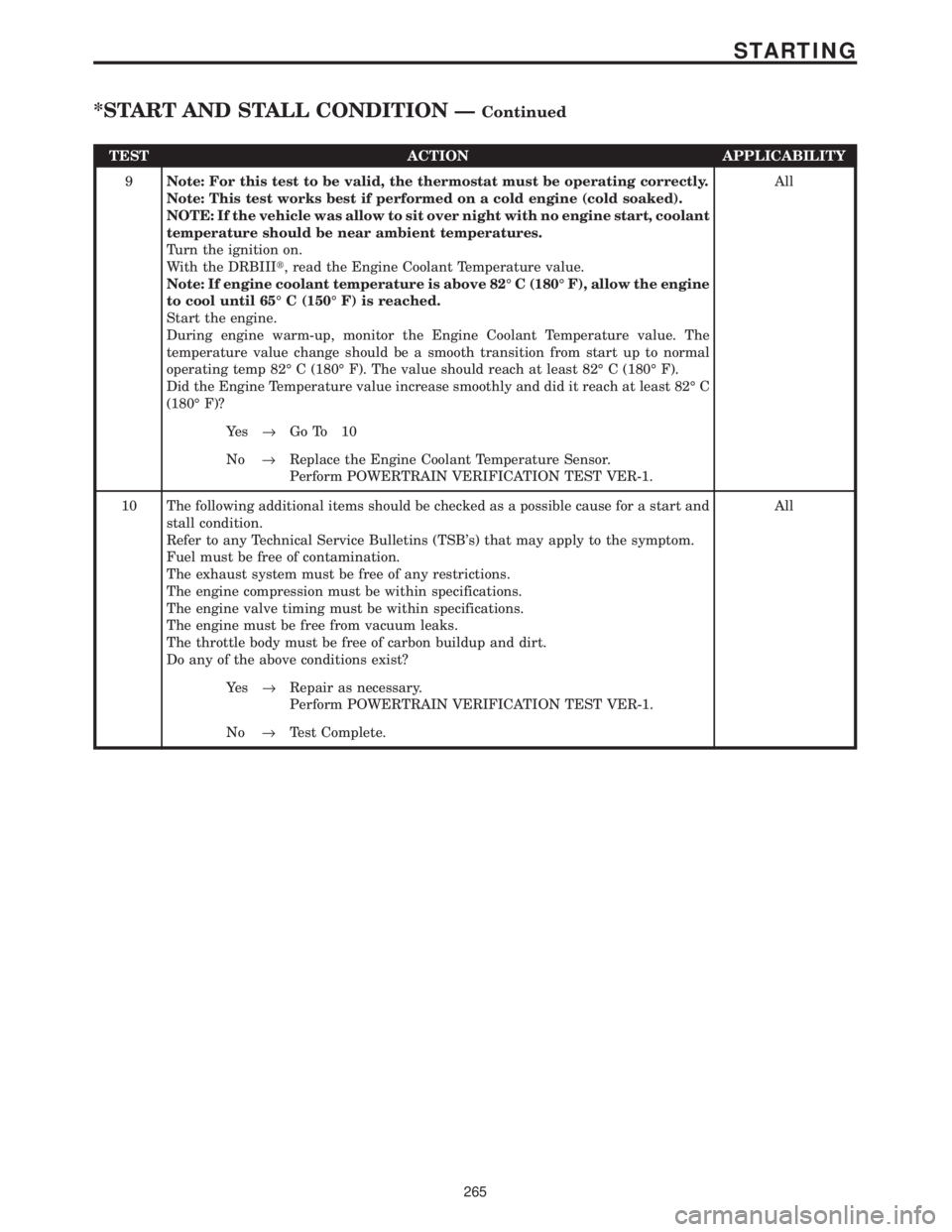
TEST ACTION APPLICABILITY
9Note: For this test to be valid, the thermostat must be operating correctly.
Note: This test works best if performed on a cold engine (cold soaked).
NOTE: If the vehicle was allow to sit over night with no engine start, coolant
temperature should be near ambient temperatures.
Turn the ignition on.
With the DRBIIIt, read the Engine Coolant Temperature value.
Note: If engine coolant temperature is above 82É C (180É F), allow the engine
to cool until 65É C (150É F) is reached.
Start the engine.
During engine warm-up, monitor the Engine Coolant Temperature value. The
temperature value change should be a smooth transition from start up to normal
operating temp 82É C (180É F). The value should reach at least 82É C (180É F).
Did the Engine Temperature value increase smoothly and did it reach at least 82É C
(180É F)?All
Ye s®Go To 10
No®Replace the Engine Coolant Temperature Sensor.
Perform POWERTRAIN VERIFICATION TEST VER-1.
10 The following additional items should be checked as a possible cause for a start and
stall condition.
Refer to any Technical Service Bulletins (TSB's) that may apply to the symptom.
Fuel must be free of contamination.
The exhaust system must be free of any restrictions.
The engine compression must be within specifications.
The engine valve timing must be within specifications.
The engine must be free from vacuum leaks.
The throttle body must be free of carbon buildup and dirt.
Do any of the above conditions exist?All
Ye s®Repair as necessary.
Perform POWERTRAIN VERIFICATION TEST VER-1.
No®Test Complete.
265
STARTING
*START AND STALL CONDITION ÐContinued
Page 4074 of 4284
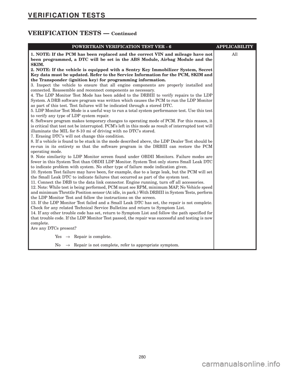
POWERTRAIN VERIFICATION TEST VER - 6 APPLICABILITY
1. NOTE: If the PCM has been replaced and the correct VIN and mileage have not
been programmed, a DTC will be set in the ABS Module, Airbag Module and the
SKIM.
2. NOTE: If the vehicle is equipped with a Sentry Key Immobilizer System, Secret
Key data must be updated. Refer to the Service Information for the PCM, SKIM and
the Transponder (ignition key) for programming information.
3. Inspect the vehicle to ensure that all engine components are properly installed and
connected. Reassemble and reconnect components as necessary.
4. The LDP Monitor Test Mode has been added to the DRBIII to verify repairs to the LDP
System. A DRB software program was written which causes the PCM to run the LDP Monitor
as part of this test. Test failures will be indicated through a stored DTC.
5. LDP Monitor Test Mode is a useful way to run a total system performance test. Use this test
to verify any type of LDP system repair.
6. Software program makes temporary changes to operating mode of PCM. For this reason, it
is critical that test not be interrupted. PCM's left in this mode as result of interrupted test will
illuminate the MIL for 8-10 mi of driving with no DTC's stored.
7. Erasing DTC's will not change this condition.
8. If a vehicle is found to be stuck in the mode described above, the LDP Dealer Test should be
re-run in its entirety so that the software program in the DRBIII can restore the PCM
operating mode.
9. Note similarity to LDP Monitor screen found under OBDII Monitors. Failure modes are
fewer in this System Test than OBDII LDP Monitor. System Test only stores Small Leak DTC
to indicate problem with system. No other type of failure mode indication given.
10. System Test failure may have been, for example, due to a large leak, but the PCM will set
the Small Leak DTC to indicate failures that occurred as part of the system test.
11. Connect the DRB to the data link connector. Engine running, turn off all accessories.
12. Note: While test is being performed, PCM must see RPM, minimum MAP, No Vehicle speed
and minimum Throttle Position sensor (At idle, in park.) With DRBIII in System Tests, perform
the LDP Monitor Test and follow the instructions on the screen.
13. If the LDP Monitor Test failed and a Small Leak DTC has set, the repair is not complete.
Check for any related Technical Service Bulletins and return to Symptom List.
14. If any other trouble code has set, return to Symptom List and follow the path specified for
that trouble code. If the LDP Monitor Test passed, the repair was successful and testing is now
complete.
Are any DTCs present?All
Ye s®Repair is complete.
No®Repair is not complete, refer to appropriate symptom.
280
VERIFICATION TESTS
VERIFICATION TESTS ÐContinued
Page 4080 of 4284
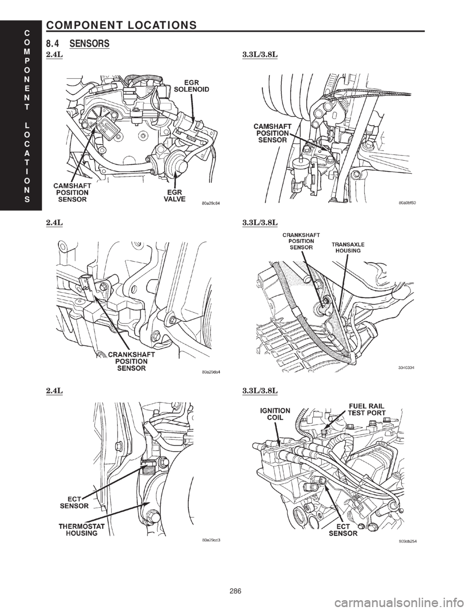
8.4 SENSORS
2.4L3.3L/3.8L
2.4L3.3L/3.8L
2.4L3.3L/3.8L
C
O
M
P
O
N
E
N
T
L
O
C
A
T
I
O
N
S
286
COMPONENT LOCATIONS