2001 BMW 525i service
[x] Cancel search: servicePage 807 of 1002

Downloaded from www.Manualslib.com manuals search engine
1 410 Fenders. Engine Hood
General ........................... .41 0.2 Engine Hood ...................... 410-6
Special tools ........................ .41 0.2 Hood, raising to service position ......... 410-6
........... Hood. removing and installing 41 0-7 Front Fenders ..................... .41 0.2 Hood. aligning ....................... 41 0-8 Front fender. removing and installing ..... .41 0.2 Hood latch components ............... 41 0-10
Hood release cable and
spring pins, adjusting
................. 410-1 1
Page 808 of 1002

Downloaded from www.Manualslib.com manuals search engine
[Fenders, Engine Hood
This repair group covers replacement of the front fenders and
removal and installation of the engine hood.
NOJE-
The body is painted at the factory affer assembly Realign-
ment of body panels may expose unpainted metal. Paint all
exposed metal once the work is complete.
Special tools
Most body repairs can be performed using regular automotive
service tools. Some BMW special tools are required to set
body pieces into the
service positions.
Front fender, removing and installing
- Raise front of vehicle and remove wheel
WARNING-
Make sure that the car is firmly supported on jack stands de-
signed for the purpose.
Placejaclr stands beneath structural
chassis points. Do not place jack stands under suspension
parts.
- Raise hood to service position. See Hood, raising to ser-
vice position.
4 Working beneath vehicle, remove fasteners (arrows) from
left side floor panel and remove panel.
- Remove inner plastic liner from wheel housing.
Page 812 of 1002

Downloaded from www.Manualslib.com manuals search engine
Hood, raising to service position
CAUTION-
Do not switch on the windshield wipers with the engine
hood raised. As a precaution, remove the wiper
motor
fuse. See 610 Electrical Component Locations.
The
hoodis heavy Before removing the hoodsupports,
be sure to have an assistant help support the hood.
< Open hood fully. With the help of a partner, support hood and
remove retaining clips (arrow) on upper end of pressurized
lifting struts. Pull struts off hood.
< Raise hood to service position and loclc in position by placing
bolts (arrow) in right and
left hinges.
Page 865 of 1002

Downloaded from www.Manualslib.com manuals search engine
1 512 Door Windows
................... General ........................... .51 2.2 Window Service .51 2.5
........... Special tools ........................ .51 2.2 Window anti-trap strip, testing 512-6
..... Power windows ...................... .51 2.2 Front window anti-trap strip, removing 512-6
..... Window switches .................... .51 2.3 Rear window anti-trap strip, removing 51 2-7
................ Rear window child lockout switch ........ .51 2.3 Door window. adjusting 51 2-8
..... Power window motors ................. .51 2.4 Door window. removing and installing 51 2-9
........... Convenience openinglclosing .51 2.4 Window Regulator Service ......... 51 2-1
Window anti-trap protection ............ .51 2-4 Front window regulator removing
Window motor limit stop function ........ .51 2.5 ....................... and installing 51 2-1 1
Rear window regulator. removing
....................... and installing 51 2-1 3
Page 866 of 1002

Downloaded from www.Manualslib.com manuals search engine
51 2-2
I Door Windows 1
This repair group covers door glass, window regulator and
power window motor repair information.
CA U JIO&
All E39 models are equipped with side-impact airbags in the
front doors. Some models are also equipped with
airbags in
the rear doors. Be sure to read the
airbag warnings and cau-
tions in 721
Airbag System (SRS).
Electric window switch replacement is covered in 612
Switches.
The windshield, rear window, fixed rear doorglass, and cargo
compartment glass (Sport Wagon only) are bonded using
special adhesives and tools. It is recommended that bonded
glass replacement be done by an authorized
BMW service fa-
cility or an automotive glass installer.
Special tools
Some window repair operations require special tools.
Power windows
- Power window features in E39 models include:
Control of the front and rear door window motors is carried
out directly by the General Module (GM
Ill).
One-touch operation in both directions on all four windows.
Cable type window regulator used for all door windows.
. Anti-trap protection provided by pressure sensitive finger
guard.
Right front and each rear door has a single window switch
located in door handle trim.
Rear door window switches can be deactivated by press-
ing child lock-out switch in the driver's window switch block.
Convenience closinglopening of the windows from driver's
loci( cylinder or convenience opening only from remote un-
lociting feature (FZV) remote key.
Window (FZV) operation can be owner customized with
Car Memory function. See 515 Central Locking and Anti-
Theft.
After ignition is switched off, electric windows can be oper-
ated until a door is opened or until
I6 minutes has elapsed.
The GM
IiI bases window motor end position on current
draw (load). There is a maximum window motor run time of
6 seconds. The motor is then switched off even if the end
position load sensor fails.
Page 869 of 1002

Downloaded from www.Manualslib.com manuals search engine
Door windows1
Window motor limit stop function
If repeated window activation (upldown cycles) exceeds one
minute, the
GM Ill deactivates the internal relays and disre-
gards any further
upldown requests. The GM Ill provides mo-
tor activation after a short duration but not for the full one
minute monitoring cycle.
The
GM Ill monitors the number of times a window motor is
activated. It counts each cycle and stores the number in
memory. Afler the stop function limit is reached and the win-
dow motor is deactivated, the
GM Ill slowly reverses the
stored count of activation until the stored number equals
0,
thus allowing the window motor to cool down.
WARNING-
* Always wear hand and eye protection when working with
brolen glass.
If a window is brolen, all of the glass bits should be
vacuumed out of the door cavity. Use a blunt
so-ewdi-iv-
er to clean out any remaining glass pieces from the
window guide rails.
When servicing the door windows, the harness con-
nector to the window regulator should always be dis-
connected to prevent pinching fingers in the moving
window mechanism.
Sedan and Sport Wagon doors are similar. Use the following
procedures for window service on these models.
WARNING-
E39 cars are iitted with side-impact airbags in the front
doors. Some are equipped with
airbags in the rear doors
as well. When
servicing the door windows on cars with
side-impact airbags, always disconnect the negative
(-)
battery cable. See 721 Airbag System (SRS) for cau-
tions and procedures relating to the
airbag system.
* Prior to disconnecting the battery, read the battery dis-
connection cautionsgiven
001 General Warnings and
Cautions.
Page 880 of 1002

Downloaded from www.Manualslib.com manuals search engine
I lnterior Trim
This repair group covers interior trim removal and installation
procedures.
- Refer to the following repair groups for additional information:
250 Gearshift Linkage
41 1 Doors (interior door panels)
@ 612 Switches
620 Instruments
640 Heating and Air Conditioning [IHKA control panel!
650 Radio
721 Airbag System (SRS)
lnterior trim repairs
lnterior trim and finish panels are clipped or screwed into
place. Many of the trim retaining clips are designed
to be used
only once. When removing trim that is held in place with clips,
it is a good idea to have spare clips on hand before beginning
the job.
WARNING-
Special precautions must be observed when servicing the
BMWSupplementai Restraint System (SRS). Serious inju-
ry may result if system service is attempted by persons un-
familiar with the BMW
SRS and its approved service
procedures. BMW
speciiies that all inspection and service
should be performed by an authorized BMW
dealer.
Before performing any work involving airbags, discon-
nect the negative
() battery cable. See 721 Airbag
System (SRS).
Airbags contain a back-uppowersupply within the SRS
control module. A
5 second discharge period should be
allowed after the battery cable has been disconnected.
CAUTION-
* When working on electrical switclies or lights, always dis-
connect the negative
(-) cable from the battery and insu-
late the cable end to prevent accidental reconnection.
a Prior to disconnecting the battery, read the battery dis-
connection cautions given in
W1 General Warnings
and Cautions.
To prevent marring the trim when working on interior
components, work with plastic prying
tools or wrap the
tips of screwdrivers and pliers with tape before prying
Page 896 of 1002

Downloaded from www.Manualslib.com manuals search engine
51 5-2
/Central Locking and Anti-Theft
This section covers repair information for door, trunk and car-
go compartment locks, central locking, electronic
immob~liza-
tion (EWS) and anti-theft alarm (DWA).
€39 cars are equipped with sophisticated self-diagnostic elec-
trical systems. When experiencing malfunctions relating to
central locking. EWS or anti-theft systems, start the diagnosis
process using the
BMW service tester DIS, GT 1, MoDiC or
equivalent scan tool. An advanced diagnostic scan tool can
usually pinpoint electrical faults quickly and safely.
Additional electrical information can be found in:
610 Electrical Component Locations
ELE Electrical Wiring Diagrams
Central locking in E39 vehicles controls the door
locks, trunk
or tailgate lock and fuel filler flap lock. The control module for
the Central Body Electronics system (ZKE
Ill), lknown as the
General Module (GM
Ill), controls central locking.
ZKE
Ill manages the following central locking related func-
tions:
Central locking
* Keyless entry
Key memory
Power trunk release
Electric opening of tailgate
DWA alarm system
Diagnosis
General Module
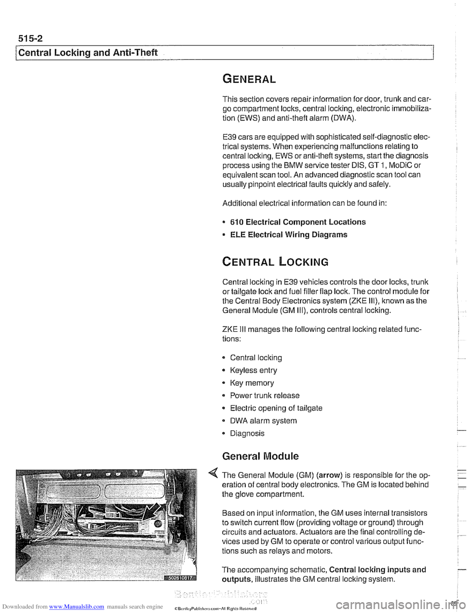
4 The General Module (GM) (arrow) is responsible for the op-
eration of central body electronics. The GM is located behind
the glove compartment.
Based on input information, the GM uses internal transistors
to switch current flow (providing voltage or ground) through
circuits and actuators. Actuators are the final controlling de-
vices used by GM to operate or control various output func-
tions such as relays and motors.
The accompanying schematic, Central locking inputs and
outputs, illustrates the GM central locking system.