2001 BMW 525i Electrical system-general
[x] Cancel search: Electrical system-generalPage 3 of 1002

Downloaded from www.Manualslib.com manuals search engine
YOU are now in Volume I
I
Foreword ................... .. ........................................................................\
.......... v
Index
........................ .. ................................................................ rear of manual
General, 001 General Warnings and Cautions 002 Vehicle Identification and VIN Decoder
Maintenance OiO 020 Maintenance
Engine
100 Engine-General 110 Engine Removal and Installation
113 Cylinder Head Removal and
Installation
116 Cyiinder Head and Valvetrain 117 Camshaft Timing Chain
119 Lubrication System
200 Transmission-General
2 Transmission 210 clutch 230 ManualTransmission
I20 Ignition System
121 Battery, Starter, Alternator
130 Fuel Injection
160 Fuel Tank and Fuel Pump 170 Radiator and Cooling System
180 Exhaust System
240 Automatic Transmission
250 Gearshift Linkage 260 Driveshaft
Suspension, 300 Suspension, Steering and 330 Rear Suspension
Brakes-General 331 Final Drive
Steering and No Front Suspension 340 Brakes
320 Steering and Wheel Alignment
400 Body-General
410 Fenders, Engine Hood 411 Doors
412 Trunk Lid, Tailgate
510 Exterior Trim, Bumpers 512 Door Windows
Equipment 513 Interior Trim
7
Equipment and 720 seat Belts
Accessories 721 Airbag System (SRS)
OBD On-Board Diagnostics
. ............ ..
515 Central Lociting and
Anti-Theft
520 Seats 540 Sunroof
.................................................................... Foreword .............................. .. v
Index ................... .. ................................................................ rear of manual
Electrical
6 system
600 Electrical System-General 620 Instruments
610 Electrical Comoonent Locations 630 Liohts
611 wipers and washers 612 Switches eati in^ and Air Conditioning
Radio
. ........... ........ .........................
Electrical Wiring Diagrams
Page 20 of 1002

Downloaded from www.Manualslib.com manuals search engine
01 0-1 0
General
Electrical testing
Many electrical problems can be understood and solved with
only a little fundamental knowledge of how electrical circuits
function.
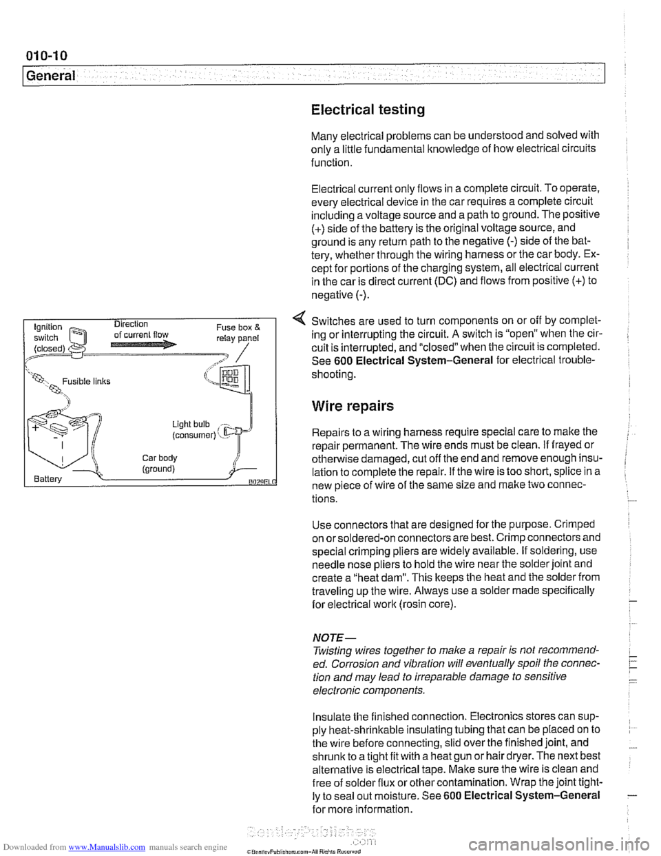
Electrical current
only flows in a complete circuit. To operate.
every electrical device in the car requires a complete circuit
including a voltage source and a path to ground. The positive
(+) side of the battery is the original voltage source, and
ground is any return path to the negative
(-) side of the bat-
tery, whether through the wiring harness or the car body. Ex-
cept for portions of the charging system, all electrical current
in the car is direct current (DC) and flows from positive
(+) to
negative
(-).
4 Switches are used to turn components on or off by complet-
ing or interrupting the circuit.
A switch is "open" when the cir-
cuit is interrupted, and "closed" when the circuit is completed.
See
600 Electrical System-General for electrical trouble-
(LW, 1 shooting
Wire repairs
Light bulb
(consumer) ' - Repairs to a wiring harness require special care to make the
repair permanent. The wire ends must be clean.
if frayed or
Car body otherwise damaged, cut off the end and remove enough insu- (ground) i Battery lation to complete the repair. if the wire is too short, splice in a BOZLiEL new piece of wire of the same size and make two connec-
tions.
Use connectors that are designed for the purpose. Crimped
on orsoldered-on connectors are best. Crimp connectors and
special crimping pliers are widely available. If soldering, use
needle nose pliers to hold the wire near the solder joint and
create a "heat dam". This keeps the heat and the solder from
traveling up the wire. Always use a solder made specifically
for electrical
work (rosin core).
NOJE-
Twisting wires together to make a repair is not recommend-
ed. Corrosion and vibration will eventually spoil the connec-
tion and may lead to irreparable damage to sensitive
electronic components.
Insulate the finished connection. Electronics stores can sup-
ply heat-shrinkable insulating tubing that can be placed on to
the wire before connecting, slid over the finished joint, and
shrunic to a tight fit with a heat gun or hair dryer. The next best
alternative is electrical tape. Make sure the wire is clean and
free of
solder flux or other contamination. Wrap the joint tight-
ly to seal out moisture. See
600 Electrical System-General
for more information.
Page 71 of 1002

Downloaded from www.Manualslib.com manuals search engine
Two common causes of driveability problems are incorrect
system voltage and bad grounds.
System voltage
Digital motor electronics (DME) requires that the system (bat-
tery) voltage be maintained within a narrow range of DC volt-
age.
DC voltage levels beyond or below the operating range,
or any
AIC voltage in the electrical system can cause havoc.
When troubleshooting an illuminated MIL, make sure the bat-
tery is fully charged and capable of delivering all its power to
the electrical system. An undercharged battery can amplify
AIC alternator output ripple.
To
make a quick check of the battery charge, measure the
voltage across the battery terminals with all cables attached
and the ignition off.
Afully charged battery will measure 12.6
volts or slightly more, compared to 12.1 5 volts for a battery
with a 25% charge.
The DME system operates at low voltage and current levels,
making it sensitive to small increases in resistance. The elec-
trical system is routinely subjected to corrosion, vibration and
wear, so faults or corrosion in the wiring harness and connec-
tors are not uncommon. Check the battery terminals
forcorro-
sion or loose cable connections. See 121 Battery, Starter,
Alternator for additional information.
If a battery cable connection has no
v~sible faults but is still
suspect, measure the voltage drop across the connection. A
large drop indicates excessive resistance, meaning that the
connection is corroded, dirty, or damaged. Clean or repairthe
connection and retest.
NOTE-
For instructions on conducting a voltage drop test and other
general electrical troubleshooting information, see
600 Elec-
trical System-General.
Visually inspect all wiring, connectors, switches and fuses in
the system. Loose or damaged connectors can cause inter-
mittent problems, especially the small terminals in the ECM
connectors. Disconnect the wiring harness connectors to
check for corrosion, and use electrical cleaning spray to re-
move contaminants.
Main grounds
Good grounds are critical to proper DME operation. If a
ground connection has no visible faults but is still suspect.
measure the voltage drop across the connection. A large volt-
age drop means high resistance. Clean or repair the connec-
tion and retest.
LBuntr.yP~sbhnllcn.can#-AII A,~iltl Rcsrwsd
Page 368 of 1002

Downloaded from www.Manualslib.com manuals search engine
- -
Battery, Starter, Alternator
This section covers the battery, alternator, starter and associ-
ated components of the electrical system.
Troubleshooting information
forthese components isfound in
Table a. Battery, alternator and starter troubleshooting.
For additional electrical troubleshooting information, see
600 Electrical System-General.
Special tools
4 Automotive digital multimeter
CAUTION-
Only use a digital multirneter when testing automotive electri- I) cal components.
4 Closed-circuit current measurement adaptor
(Tool No.
BMW 61 2 300)
Engine electrical system
The alternator and starter are wired directly to the battery. To
prevent accidental shorts that might blow a fuse or damage
wires and electrical components, always disconnect the
negative
(-) battery cable before working on the electrical
system.
Various versions of alternators, voltage regulators, starters,
and batteries are used in
E39 cars. Replace components ac-
cording to the original equipment specification.
Page 805 of 1002

Downloaded from www.Manualslib.com manuals search engine
Instrument cluster
Instrument cluster uses large easy-to-read analog instru-
ments and is removable as a unit without removing the dash-
board. On-board computer and Check Control functions are
integrated into the instrument cluster displays.
Service Interval Display
Service Interval Display calculates vehicle service needs
based on current driving patterns, and indicates to the driver
when the car requires
service
On-board navigation
An integrated on-board navigation system, based on Global
Positioning System (GPS) technology, is optionally available
on
E39 cars. When installed, a multifunction monitor is includ-
ed in the center of the dash above the radio. in addition to dis-
playing navigation system information, this monitor accesses
On-Board Computerfunctions, audiosystem controls, mobile
phone dialling and memory, and automatic ventilation.
Park Distance Control (PDC)
Park Distance Control (PDC) is an optional system which
uses ultrasonic sensors in the rear bumper trim to warn the
driver of approaching too close to obstacles when parlting.
Central body electronics
E39 vehicles are equipped with an integrated complex of
electronic modules connected mostly via K-Bus. This system,
called central body electronics (ZKE
Ill), is primarily con-
trolled by the general module (GM
Ill). An overview of ZKE Ill
functions is found in 600 Electrical System-General. Details
of ZKE
Ill functioning is in the following repair groups:
- 512 Door Windows
* 515 Central Locking and Aniti-Theft
520 Seats
a 540 Sunroof
611 Wipers and Washers
620 Instruments