Page 3 of 1002

Downloaded from www.Manualslib.com manuals search engine
YOU are now in Volume I
I
Foreword ................... .. ........................................................................\
.......... v
Index
........................ .. ................................................................ rear of manual
General, 001 General Warnings and Cautions 002 Vehicle Identification and VIN Decoder
Maintenance OiO 020 Maintenance
Engine
100 Engine-General 110 Engine Removal and Installation
113 Cylinder Head Removal and
Installation
116 Cyiinder Head and Valvetrain 117 Camshaft Timing Chain
119 Lubrication System
200 Transmission-General
2 Transmission 210 clutch 230 ManualTransmission
I20 Ignition System
121 Battery, Starter, Alternator
130 Fuel Injection
160 Fuel Tank and Fuel Pump 170 Radiator and Cooling System
180 Exhaust System
240 Automatic Transmission
250 Gearshift Linkage 260 Driveshaft
Suspension, 300 Suspension, Steering and 330 Rear Suspension
Brakes-General 331 Final Drive
Steering and No Front Suspension 340 Brakes
320 Steering and Wheel Alignment
400 Body-General
410 Fenders, Engine Hood 411 Doors
412 Trunk Lid, Tailgate
510 Exterior Trim, Bumpers 512 Door Windows
Equipment 513 Interior Trim
7
Equipment and 720 seat Belts
Accessories 721 Airbag System (SRS)
OBD On-Board Diagnostics
. ............ ..
515 Central Lociting and
Anti-Theft
520 Seats 540 Sunroof
.................................................................... Foreword .............................. .. v
Index ................... .. ................................................................ rear of manual
Electrical
6 system
600 Electrical System-General 620 Instruments
610 Electrical Comoonent Locations 630 Liohts
611 wipers and washers 612 Switches eati in^ and Air Conditioning
Radio
. ........... ........ .........................
Electrical Wiring Diagrams
Page 831 of 1002
Downloaded from www.Manualslib.com manuals search engine
Trunk Lid, Tailgate
4 Pry out trunk light and disconnect electrical harness plug
connector.
- Gently pry trunk liner away from lid and remove.
4 Disconnect Wiring connectors A, B and C. Remove wiring
harness by pulling through opening in lid frame
D.
While supporting trunk lid, loosen left and right top hinge fas-
teners (arrow
A) and remove lower fasteners (arrow B).
NOTE-
Before loosening hinge bolts, mark hinge and hinge bolt lo-
cations for
reins~alla~on
Lift trunk lid straight up to remove.
Installation is reverse of removal. If necessary, align trunk lid
to body as described in
Trunk lid, adjusting.
Page 838 of 1002

Downloaded from www.Manualslib.com manuals search engine
.-
l~runk Lid, Tailgate
Starting at top, pull down (arrow) on trim cover. Carefully re-
move wiring harness support clip from trim cover.
NOTE-
Tailgate window trim cover and weather stripping shown in
place.
Insert BMW special tool 51 2
153 into body cavity below
hinge.
WARNING-
Tlie tailgate is ve!y heavy and will close without both pressu-
rized liftinq struts installed. Properly support
tailgafe prior to r
1 removal of the lifting struts.
- Working at hinge end of strut, remove strut retaining clip and
remove strut from mounting pin.
Slide BMW special tool 51 2 152 over strut until end of tool is
aligned with strut pin
(arrow).
Press down on outer end of special tool to release inner
strut mount.
Remove special tool with strut.
When installing strut make sure ball cup is pointing straight
down.
Rema~nder of installation 1s reverse of removal.
Tailgate gas strut, removing and installing
- Open tailgate and support.
Remove tailgate hinge trim panel fasteners
(A).
Page 839 of 1002

Downloaded from www.Manualslib.com manuals search engine
Trunk Lid, Tailgate
Starting at top, pull down (arrow) on trim cover. Carefully re-
move wiring harness support clip from trim cover.
Install protective plate
(BMW special tool 51 2 153) between
roof panel and hinges.
WARNING -
The tailgate is very heavy and will close without both pressu-
rized lifting
struts installed. Properly support tailgate prior to
removal of the lifting struts.
Worlting at left side:
Remove gas strut retaining clip and pin (arrow).
4 Insert BMW special tool 51 2 151 over strut.
NOTE-
BMW special tool 51 2 151 must be chamfered in area (A).
Press tool down to release inner end of gas strut.
Push strut forward and toward center of vehicle to remove.
- When installing strut make sure ball cup is pointing straight
down.
- Remainder of installation is reverse of removal.
Tailgate, removing and installing
- Remove radio antenna amplifier. See 650 Radio.
- Disconnect outer end of window and tailgate gas struts. See
Rear window gas strut, removing and installing and Tail-
gate gas strut, removing and installing.
WARNING-
The tailgate is very heaq and will close without both pressu-
rized lifling struts installed. Properly support tailgate prior to
removal of the lifling struts.
- Remove trim panel from tailgate.
Page 896 of 1002

Downloaded from www.Manualslib.com manuals search engine
51 5-2
/Central Locking and Anti-Theft
This section covers repair information for door, trunk and car-
go compartment locks, central locking, electronic
immob~liza-
tion (EWS) and anti-theft alarm (DWA).
€39 cars are equipped with sophisticated self-diagnostic elec-
trical systems. When experiencing malfunctions relating to
central locking. EWS or anti-theft systems, start the diagnosis
process using the
BMW service tester DIS, GT 1, MoDiC or
equivalent scan tool. An advanced diagnostic scan tool can
usually pinpoint electrical faults quickly and safely.
Additional electrical information can be found in:
610 Electrical Component Locations
ELE Electrical Wiring Diagrams
Central locking in E39 vehicles controls the door
locks, trunk
or tailgate lock and fuel filler flap lock. The control module for
the Central Body Electronics system (ZKE
Ill), lknown as the
General Module (GM
Ill), controls central locking.
ZKE
Ill manages the following central locking related func-
tions:
Central locking
* Keyless entry
Key memory
Power trunk release
Electric opening of tailgate
DWA alarm system
Diagnosis
General Module
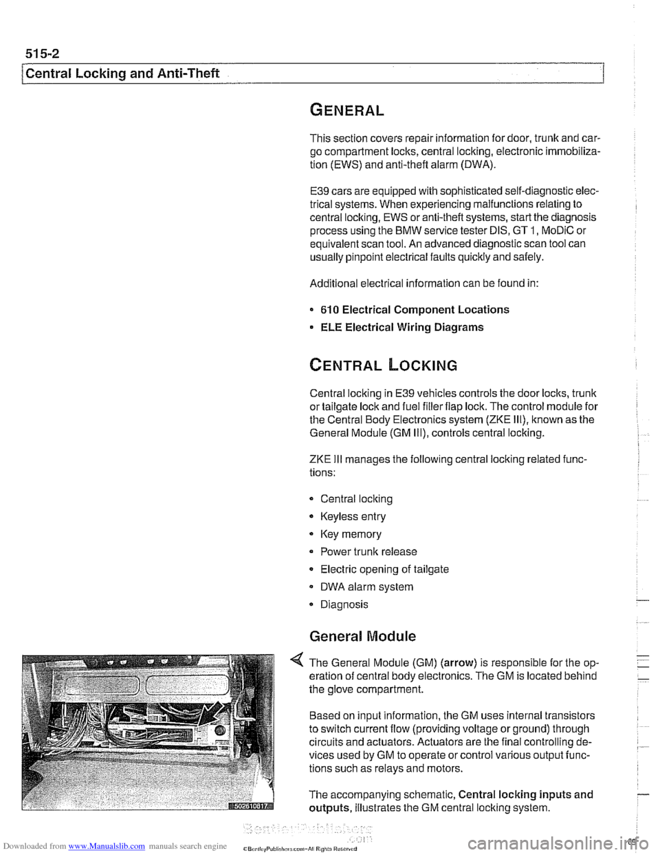
4 The General Module (GM) (arrow) is responsible for the op-
eration of central body electronics. The GM is located behind
the glove compartment.
Based on input information, the GM uses internal transistors
to switch current flow (providing voltage or ground) through
circuits and actuators. Actuators are the final controlling de-
vices used by GM to operate or control various output func-
tions such as relays and motors.
The accompanying schematic, Central locking inputs and
outputs, illustrates the GM central locking system.