Page 71 of 88
Downloaded from www.Manualslib.com manuals search engine
71
Interface for Navigation Plus (R94)
The interface of the Navigation System Plus
performs the following tasks:
– Exchange of data bus information -
Navigation System Plus internal data bus
– Transfer of TMC data to the Navigation
System Plus for dynamic route planning
In order to receive the TMC data, an interface
connects the aerial and radio.
The following data is exchanged via the
interface:
Display request/instrument cluster
Traffic news/Telematics
Fault messages/card reader
Control signals/multi-function
steering wheel
Terminal 15/steering column
electronicsDisplay/instrument cluster
Control signals data bus/data bus
information system
Vehicle data/card reader Input from data bus
information/senderOutput to data bus
information/receiver
SSP254_122
Page 72 of 88

Downloaded from www.Manualslib.com manuals search engine
72
TS
TS
Multi-communication bar (MCB)
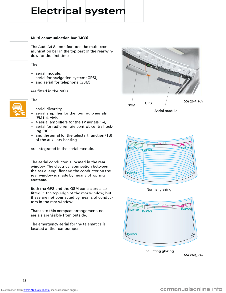
The Audi A4 Saloon features the multi-com-
munication bar in the top part of the rear win-
dow for the first time.
The
– aerial module,
– aerial for navigation system (GPS),+
– and aerial for telephone (GSM)
are fitted in the MCB.
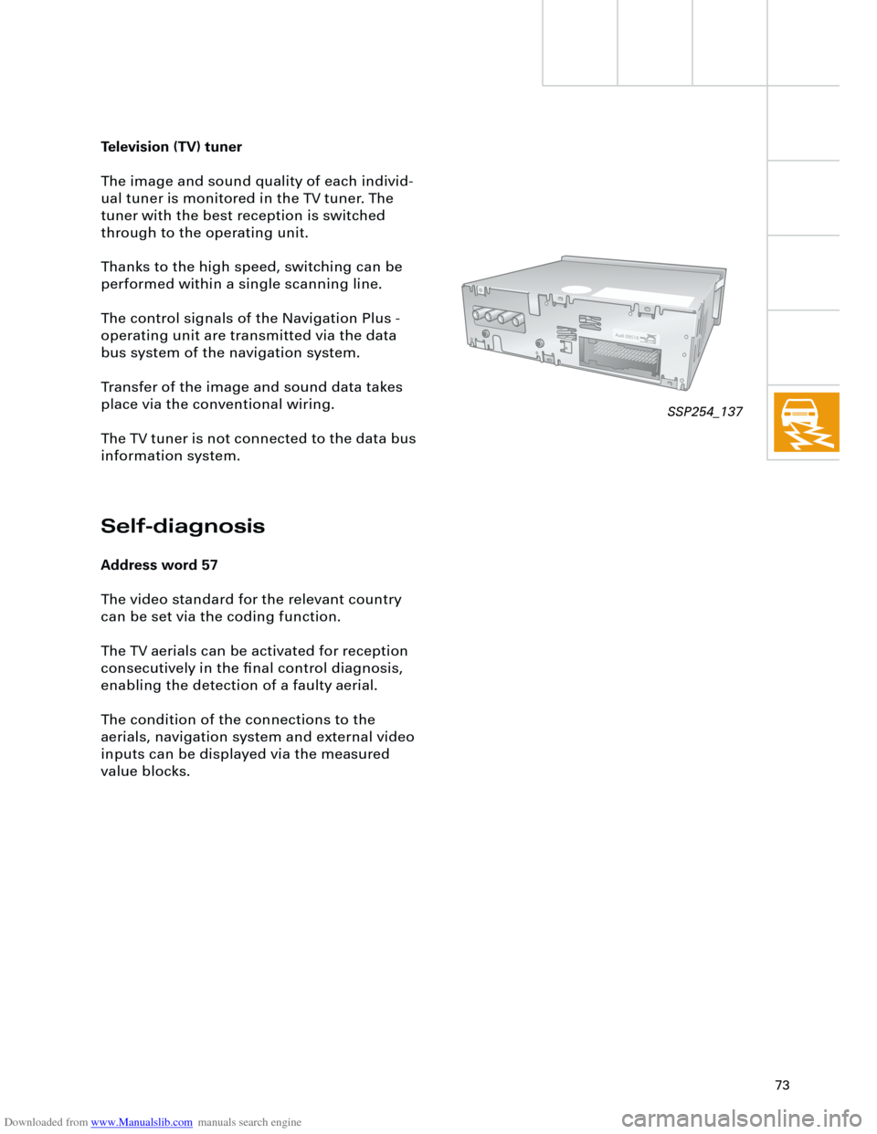
The
– aerial diversity,
– aerial amplifier for the four radio aerials
(FM1-4, AM),
– 4 aerial amplifiers for the TV aerials 1-4,
– aerial for radio remote control, central lock-
ing (RCL),
– and the aerial for the telestart function (TS)
of the auxiliary heating
are integrated in the aerial module.
The aerial conductor is located in the rear
window. The electrical connection between
the aerial amplifier and the conductor on the
rear window is made by means of spring
contacts.
Both the GPS and the GSM aerials are also
fitted in the top edge of the rear window, but
these are not connected by means of conduc-
tors in the rear window.
Thanks to this compact arrangement, no
aerials are visible from outside.
The emergency aerial for the telematics is
located at the rear bumper.
Electrical system
SSP254_109
SSP254_013
GSMGPS
Aerial module
Normal glazing
Insulating glazing
Page 73 of 88

Downloaded from www.Manualslib.com manuals search engine
73
Television (TV) tuner
The image and sound quality of each individ-
ual tuner is monitored in the TV tuner. The
tuner with the best reception is switched
through to the operating unit.
Thanks to the high speed, switching can be
performed within a single scanning line.
The control signals of the Navigation Plus -
operating unit are transmitted via the data
bus system of the navigation system.
Transfer of the image and sound data takes
place via the conventional wiring.
The TV tuner is not connected to the data bus
information system.
Self-diagnosis
Address word 57
The video standard for the relevant country
can be set via the coding function.
The TV aerials can be activated for reception
consecutively in the final control diagnosis,
enabling the detection of a faulty aerial.
The condition of the connections to the
aerials, navigation system and external video
inputs can be displayed via the measured
value blocks.
SSP254_137
Page 74 of 88
Downloaded from www.Manualslib.com manuals search engine
74
Electrical system
The electronic logbook, Audi Logbook
The Audi Logbook is a fully automatic logbook
which allows the customer to calculate
business and private journeys in order to
determine costs, e.g. for tax purposes.
The Audi Logbook is only available in
conjunction with Navigation Plus or
Navigation IV.
The Audi Logbook System includes:
– Chip card reader R99,
– PC card reader,
– Software CD for installing the Audi
Logbook program on the PC,
– Chip card.For initial operation of the Audi Logbook, the
chip card must be activated using a PC and
PC card reader (see Owner's manual).
SSP254_065
CAN bus information
+ -
SSP254_040
Page 75 of 88

Downloaded from www.Manualslib.com manuals search engine
75
In the ”business journey” mode, data relating
to
– date
– time at start of journey
– position at start of journey
– position at end of journey
– time at end of journey
– kilometres driven
are stored in the Chip card reader R99.
The date and route driven are stored In the
”private journey” mode.
The ”continue journey” mode is used to pre-
vent short breaks from being stored (e.g. refu-
elling stops).
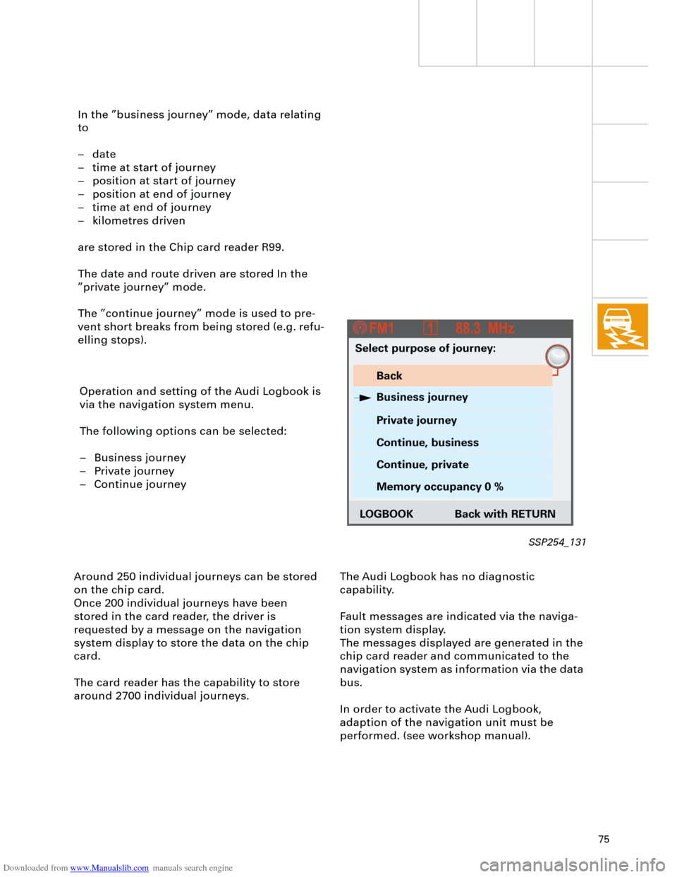
Operation and setting of the Audi Logbook is
via the navigation system menu.
The following options can be selected:
– Business journey
– Private journey
– Continue journey
Around 250 individual journeys can be stored
on the chip card.
Once 200 individual journeys have been
stored in the card reader, the driver is
requested by a message on the navigation
system display to store the data on the chip
card.
The card reader has the capability to store
around 2700 individual journeys.The Audi Logbook has no diagnostic
capability.
Fault messages are indicated via the naviga-
tion system display.
The messages displayed are generated in the
chip card reader and communicated to the
navigation system as information via the data
bus.
In order to activate the Audi Logbook,
adaption of the navigation unit must be
performed. (see workshop manual).
Select purpose of journey:
Back
Business journey
Private journey
Continue, business
Continue, private
Memory occupancy 0 %
LOGBOOK Back with RETURN
SSP254_131
Page 76 of 88

Downloaded from www.Manualslib.com manuals search engine
76
Heater/AC
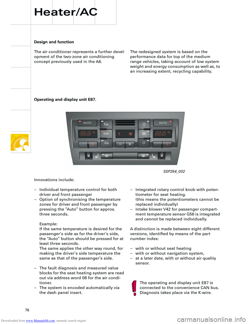
Operating and display unit E87.
The redesigned system is based on the
performance data for top of the medium
range vehicles, taking account of low system
weight and energy consumption as well as, to
an increasing extent, recycling capability.
The operating and display unit E87 is
connected to the convenience CAN bus.
Diagnosis takes place via the K-wire.
Design and function
The air conditioner represents a further devel-
opment of the two-zone air conditioning
concept previously used in the A6.
Innovations include:
– Individual temperature control for both
driver and front passenger
– Option of synchronising the temperature
zones for driver and front passenger by
pressing the ”Auto” button for approx.
three seconds.
Example:
If the same temperature is desired for the
passenger’s side as for the driver’s side,
the ”Auto” button should be pressed for at
least three seconds.
The same applies the other way round, for
making the driver’s side temperature the
same as that of the passenger’s side.
– The fault diagnosis and measured value
blocks for the seat heating system are read
out via address word 08 for the air condi-
tioner.
– The system is encoded automatically via
the dash panel insert.– Integrated rotary control knob with poten-
tiometer for seat heating.
(this means the potentiometers cannot be
replaced individually)
– Intake blower V42 for passenger compart-
ment temperature sensor G56 is integrated
and cannot be replaced individually.
A distinction is made between eight different
versions, identified by means of the part
number index:
– with or without seat heating
– with or without navigation system,
– at a later date, with or without air quality
sensor.
SSP254_032