Page 37 of 88
Downloaded from www.Manualslib.com manuals search engine
37
Side airbag crash sensor,
driver’s side G179
Control unit for
parking aid J446
Airbag control
unit J234Side airbag crash sensor, rear
driver’s side G256
passenger’s side G257
Control unit for
tyre pressure
monitor J502
SSP254_008
Door control units,
passenger side J387
rear right,
optional J389
ESP sensor
Control unit for trailer
recognition J345
Central control unit for
convenience system J393
Side airbag crash sensor,
passenger’s side G180
Door control unit,
driver’s side J386,
rear left, optional J388
Control unit for vehicle electri-
cal system J519
Page 39 of 88

Downloaded from www.Manualslib.com manuals search engine
39
CAN data bus
The Audi A4 is equipped with a widely
extended CAN data bus system.
Due to the ever increasing number of control
units installed in the vehicle and the associ-
ated requirement for data exchange, the
importance of the CAN data bus system
increases significantly.For communication between the
installed control units and the diagnos-
tic tester, two diagnosis wires (K and L)
are available.
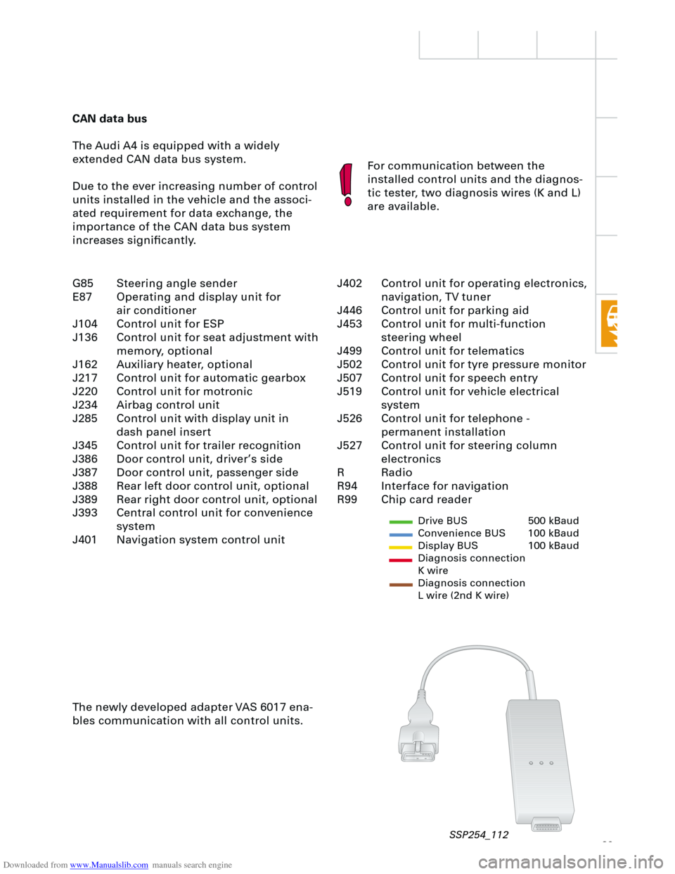
The newly developed adapter VAS 6017 ena-
bles communication with all control units.
Drive BUS 500 kBaud
Convenience BUS 100 kBaud
Display BUS 100 kBaud
Diagnosis connection
K wire
Diagnosis connection
L wire (2nd K wire)
J402 Control unit for operating electronics,
navigation, TV tuner
J446 Control unit for parking aid
J453 Control unit for multi-function
steering wheel
J499 Control unit for telematics
J502 Control unit for tyre pressure monitor
J507 Control unit for speech entry
J519 Control unit for vehicle electrical
system
J526 Control unit for telephone -
permanent installation
J527 Control unit for steering column
electronics
R Radio
R94 Interface for navigation
R99 Chip card reader G85 Steering angle sender
E87 Operating and display unit for
air conditioner
J104 Control unit for ESP
J136 Control unit for seat adjustment with
memory, optional
J162 Auxiliary heater, optional
J217 Control unit for automatic gearbox
J220 Control unit for motronic
J234 Airbag control unit
J285 Control unit with display unit in
dash panel insert
J345 Control unit for trailer recognition
J386 Door control unit, driver’s side
J387 Door control unit, passenger side
J388 Rear left door control unit, optional
J389 Rear right door control unit, optional
J393 Central control unit for convenience
system
J401 Navigation system control unit
SSP254_112
Page 44 of 88

Downloaded from www.Manualslib.com manuals search engine
44
Electrical system
Steering column switch
module
Due to the compact design of the newly
developed steering column switch module, it
was possible to minimise the amount of wir-
ing necessary and the space requirements.
A self-diagnosis facility for the steering col-
umn switch is now available with new switch
module.
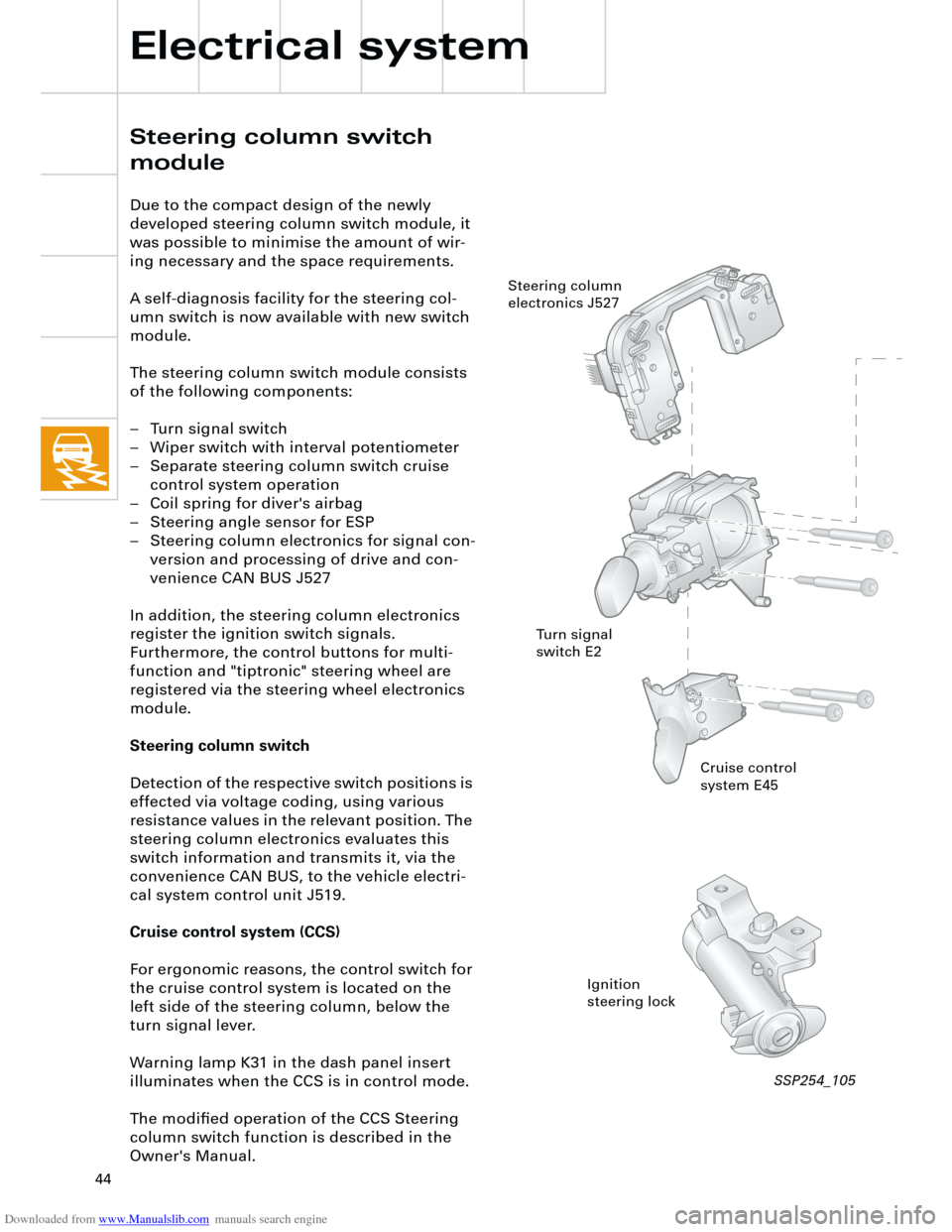
The steering column switch module consists
of the following components:
– Turn signal switch
– Wiper switch with interval potentiometer
– Separate steering column switch cruise
control system operation
– Coil spring for diver's airbag
– Steering angle sensor for ESP
– Steering column electronics for signal con-
version and processing of drive and con-
venience CAN BUS J527
In addition, the steering column electronics
register the ignition switch signals.
Furthermore, the control buttons for multi-
function and "tiptronic" steering wheel are
registered via the steering wheel electronics
module.
Steering column switch
Detection of the respective switch positions is
effected via voltage coding, using various
resistance values in the relevant position. The
steering column electronics evaluates this
switch information and transmits it, via the
convenience CAN BUS, to the vehicle electri-
cal system control unit J519.
Cruise control system (CCS)
For ergonomic reasons, the control switch for
the cruise control system is located on the
left side of the steering column, below the
turn signal lever.
Warning lamp K31 in the dash panel insert
illuminates when the CCS is in control mode.
The modified operation of the CCS Steering
column switch function is described in the
Owner's Manual.
Cruise control
system E45
Ignition
steering lock Steering column
electronics J527
Turn signal
switch E2
SSP254_105
Page 46 of 88
Downloaded from www.Manualslib.com manuals search engine
46
Auxiliary signals
1 CAN screen drive
2 Emergency vehicle distress radio
3 Emergency vehicle radio
4 Cruise control system on/off
5 CAN low convenience
6 CAN high convenience
7 CAN low drive
8 CAN high drive
9 Ignition lock terminal 75
10 Ignition lock S contact
11 Ignition lock terminal 15
12 Ignition lock terminal 50
13 Ignition lock terminal P
X
Y Connection within the functional
diagram
Z
Electrical system
Functional diagram
Steering column switch
module
(maximum equipment)
Components
E Windscreen wiper switch
E2 Turn signal switch
E45 CCS switch
E221 Operating unit in steering wheel
G85 Steering angle sender
H Horn actuation
J234 Airbag control unit
J453 Control unit for multi-function
steering wheel
J527 Control unit for steering column
electronics
S Fuse
Z36 Heated steering wheel
Colour coding
= Input signal
= Output signal
= Positive power supply
= Earth
= CAN-BUS
{
Page 59 of 88

Downloaded from www.Manualslib.com manuals search engine
59
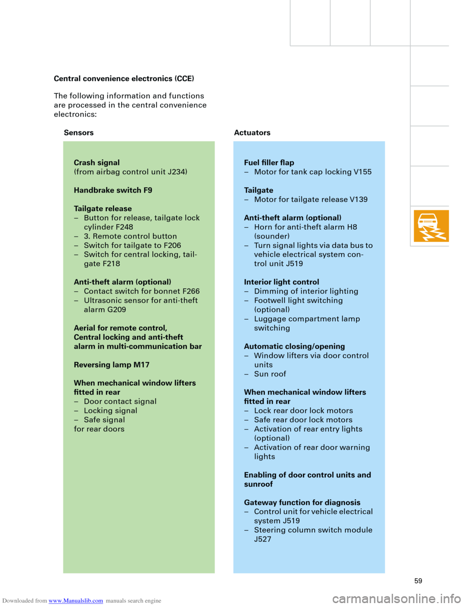
The following information and functions
are processed in the central convenience
electronics:
Crash signal
(from airbag control unit J234)
Handbrake switch F9
Tailgate release
– Button for release, tailgate lock
cylinder F248
– 3. Remote control button
– Switch for tailgate to F206
– Switch for central locking, tail-
gate F218
Anti-theft alarm (optional)
– Contact switch for bonnet F266
– Ultrasonic sensor for anti-theft
alarm G209
Aerial for remote control,
Central locking and anti-theft
alarm in multi-communication bar
Reversing lamp M17
When mechanical window lifters
fitted in rear
– Door contact signal
– Locking signal
– Safe signal
for rear doors
Fuel filler flap
– Motor for tank cap locking V155
Tailgate
– Motor for tailgate release V139
Anti-theft alarm (optional)
– Horn for anti-theft alarm H8
(sounder)
– Turn signal lights via data bus to
vehicle electrical system con-
trol unit J519
Interior light control
– Dimming of interior lighting
– Footwell light switching
(optional)
– Luggage compartment lamp
switching
Automatic closing/opening
– Window lifters via door control
units
– Sun roof
When mechanical window lifters
fitted in rear
– Lock rear door lock motors
– Safe rear door lock motors
– Activation of rear entry lights
(optional)
– Activation of rear door warning
lights
Enabling of door control units and
sunroof
Gateway function for diagnosis
– Control unit for vehicle electrical
system J519
– Steering column switch module
J527
Sensors Actuators Central convenience electronics (CCE)
Page 65 of 88

Downloaded from www.Manualslib.com manuals search engine
65
Radio chorus II, concert II and symphony II
In the new Audi A4, the new generation of
radios, chorus II, concert II and symphony II
are available as options.
The following functions have been optimised:
– AM has been extended to include long
wave.
– There are now 12 programmable stations
for AM and FM.
All three radio versions are compatible with
the external CD changer (optional).
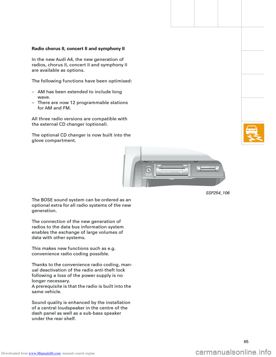
The optional CD changer is now built into the
glove compartment.
The BOSE sound system can be ordered as an
optional extra for all radio systems of the new
generation.
The connection of the new generation of
radios to the data bus information system
enables the exchange of large volumes of
data with other systems.
This makes new functions such as e.g.
convenience radio coding possible.
Thanks to the convenience radio coding, man-
ual deactivation of the radio anti-theft lock
following a loss of the power supply is no
longer necessary.
A prerequisite is that the radio is built into the
same vehicle.
Sound quality is enhanced by the installation
of a central loudspeaker in the centre of the
dash panel as well as a sub-bass speaker
under the rear shelf.
AIRBAG
OFFON
Audicd chargerCOMPAKTAKTDIGITAL AUDIOAL AUDIO
LOAD
SSP254_106