Page 16 of 109

INSTRUMENT AND CONTROL FUNCTIONS
3-2
3
EAU01590
(Parking)
The steering is locked in this position,
and the taillight and auxiliary light come
on but all other circuits are off. The key
can be removed in this position.
To use the parking position, first lock
the steering, then turn the key to “ ”.
Do not use this position for an extend-
ed length of time as the battery may
discharge.
EAU00056
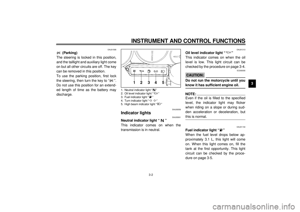
Indicator lights
EAU00061
Neutral indicator light “ ”
This indicator comes on when the
transmission is in neutral.
EAU01313
Oil level indicator light “ ”
This indicator comes on when the oil
level is low. This light circuit can be
checked by the procedure on page 3-4.
EC000000
CAUTION:@ Do not run the motorcycle until you
know it has sufficient engine oil. @NOTE:@ Even if the oil is filled to the specified
level, the indicator light may flicker
when riding on a slope or during sud-
den acceleration or deceleration, but
this is normal. @
EAU01154
Fuel indicator light “ ”
When the fuel level drops below ap-
proximately 3.1 L, this light will come
on. When this light comes on, fill the
tank at the first opportunity. This light
circuit can be checked by the proce-
dure on page 3-5.
1. Neutral indicator light “ ”
2. Oil level indicator light “ ”
3. Fuel indicator light “ ”
4. Turn indicator light “ ”
5. High beam indicator light “ ”
E_4tv_Functions.fm Page 2 Wednesday, September 1, 1999 11:10 AM
Page 23 of 109

INSTRUMENT AND CONTROL FUNCTIONS
3-9
3
EAU00138
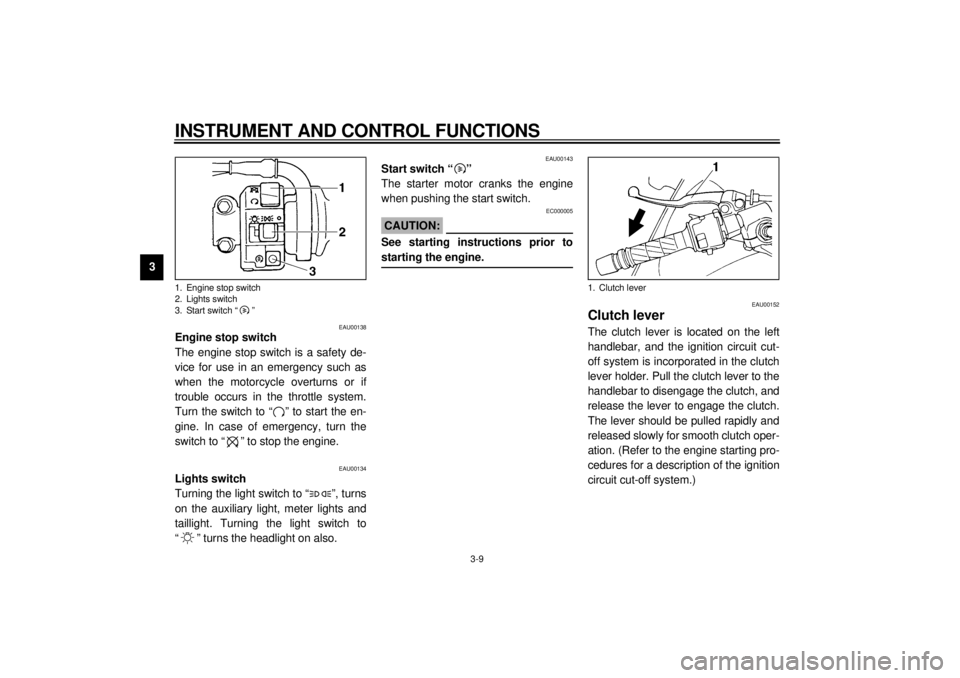
Engine stop switch
The engine stop switch is a safety de-
vice for use in an emergency such as
when the motorcycle overturns or if
trouble occurs in the throttle system.
Turn the switch to “ ” to start the en-
gine. In case of emergency, turn the
switch to “ ” to stop the engine.
EAU00134
Lights switch
Turning the light switch to “ ”, turns
on the auxiliary light, meter lights and
taillight. Turning the light switch to
“ ” turns the headlight on also.
EAU00143
Start switch “ ”
The starter motor cranks the engine
when pushing the start switch.
EC000005
CAUTION:@ See starting instructions prior to
starting the engine. @
EAU00152
Clutch leverThe clutch lever is located on the left
handlebar, and the ignition circuit cut-
off system is incorporated in the clutch
lever holder. Pull the clutch lever to the
handlebar to disengage the clutch, and
release the lever to engage the clutch.
The lever should be pulled rapidly and
released slowly for smooth clutch oper-
ation. (Refer to the engine starting pro-
cedures for a description of the ignition
circuit cut-off system.)
1. Engine stop switch
2. Lights switch
3. Start switch “ ”
1. Clutch lever
E_4tv_Functions.fm Page 9 Wednesday, September 1, 1999 11:10 AM
Page 56 of 109
PERIODIC MAINTENANCE AND MINOR REPAIR
6-6
6 2. Disconnect the auxiliary light cou-
pler and the turn signal connec-
tors.To install
1. Connect the auxiliary light coupler
and the turn signal connectors.2. Place the cowling in the original
position and install the bolts.
1. Bolt (´ 13)
1. Bolt (´ 5 on each side)
1. Auxiliary light coupler
2. Turn signal connectors
E_4tv_Periodic.fm Page 6 Wednesday, September 1, 1999 11:12 AM
Page 102 of 109
SPECIFICATIONS
8-4
8
Wheel travel
Front 130 mm
Rear 120 mm
Electrical system
Ignition system T.C.I. (digital)
Charging system
Type A.C. magneto
Standard output 14 V, 18.5 A @ 5,000 r/min
Battery
Type YTX12-BS
Voltage, capacity 12 V, 10 AH
Headlight type
Quartz bulb (halogen)
Bulb voltage, wattage
´ quantity
Headlight 12 V, 60/55 W ´ 1
Tail/brake light 12 V, 5/21 W ´ 1
Auxiliary light 12 V, 4 W ´ 1
Turn signal light 12 V, 21 W ´ 4
Meter light 12 V, 1.7 W ´ 4
Neutral indicator light 12 V, 3.4 W ´ 1
High beam indicator light 12 V, 3.4 W ´ 1
Oil level indicator light 12 V, 3.4 W ´ 1
Turn indicator light 12 V, 3.4 W ´ 1
Fuel indicator light 12 V, 3.4 W ´ 1Fuses
Main fuse 30 A
Headlight fuse 20 A
Signaling system fuse 15 A
Fan fuse 7.5 A
Ignition fuse 7.5 A
E_4tv_Spec.fm Page 4 Wednesday, September 1, 1999 11:14 AM