Page 51 of 109
6-1
6
EAU00462
6-PERIODIC MAINTENANCE AND MINOR REPAIR
EAU00464
Periodic inspection, adjustment and lu-
brication will keep your motorcycle in
the safest and most efficient condition
possible. Safety is an obligation of the
motorcycle owner. The maintenance
and lubrication schedule chart should
be considered strictly as a guide to
general maintenance and lubrication
intervals. YOU MUST TAKE INTO
CONSIDERATION THAT WEATHER,
TERRAIN, GEOGRAPHICAL LOCA-
TIONS, AND A VARIETY OF INDIVID-
UAL USES ALL TEND TO DEMAND
THAT EACH OWNER ALTER THIS
TIME SCHEDULE TO SHORTER IN-
TERVALS TO MATCH THE ENVI-
RONMENT. The most important points
of motorcycle inspection, adjustment,
and lubrication are explained in the fol-
lowing pages.
EW000060
WARNING
@ If you are not familiar with motor-
cycle service, this work should be
done by a Yamaha dealer. @
EAU00469
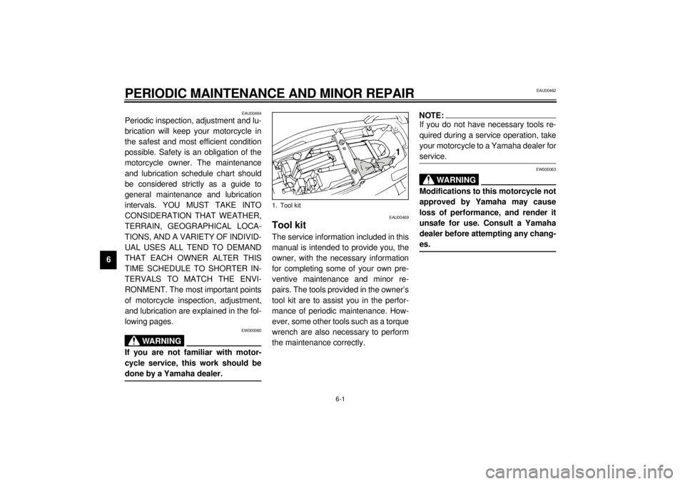
Tool kitThe service information included in this
manual is intended to provide you, the
owner, with the necessary information
for completing some of your own pre-
ventive maintenance and minor re-
pairs. The tools provided in the owner’s
tool kit are to assist you in the perfor-
mance of periodic maintenance. How-
ever, some other tools such as a torque
wrench are also necessary to perform
the maintenance correctly.
NOTE:@ If you do not have necessary tools re-
quired during a service operation, take
your motorcycle to a Yamaha dealer for
service. @
EW000063
WA R N I N G
@ Modifications to this motorcycle not
approved by Yamaha may cause
loss of performance, and render it
unsafe for use. Consult a Yamaha
dealer before attempting any chang-
es. @
1. Tool kit
E_4tv_Periodic.fm Page 1 Wednesday, September 1, 1999 11:12 AM
Page 63 of 109
PERIODIC MAINTENANCE AND MINOR REPAIR
6-13
6
EAU03025
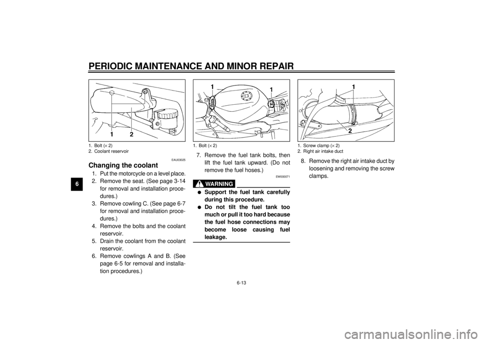
Changing the coolant1. Put the motorcycle on a level place.
2. Remove the seat. (See page 3-14
for removal and installation proce-
dures.)
3. Remove cowling C. (See page 6-7
for removal and installation proce-
dures.)
4. Remove the bolts and the coolant
reservoir.
5. Drain the coolant from the coolant
reservoir.
6. Remove cowlings A and B. (See
page 6-5 for removal and installa-
tion procedures.)7. Remove the fuel tank bolts, then
lift the fuel tank upward. (Do not
remove the fuel hoses.)
EW000071
WARNING
@ l
Support the fuel tank carefully
during this procedure.
l
Do not tilt the fuel tank too
much or pull it too hard because
the fuel hose connections may
become loose causing fuel
leakage.
@
8. Remove the right air intake duct by
loosening and removing the screw
clamps.
1. Bolt (´ 2)
2. Coolant reservoir
1. Bolt (´ 2)
1. Screw clamp (´ 2)
2. Right air intake duct
E_4tv_Periodic.fm Page 13 Wednesday, September 1, 1999 11:12 AM
Page 64 of 109
PERIODIC MAINTENANCE AND MINOR REPAIR
6-14
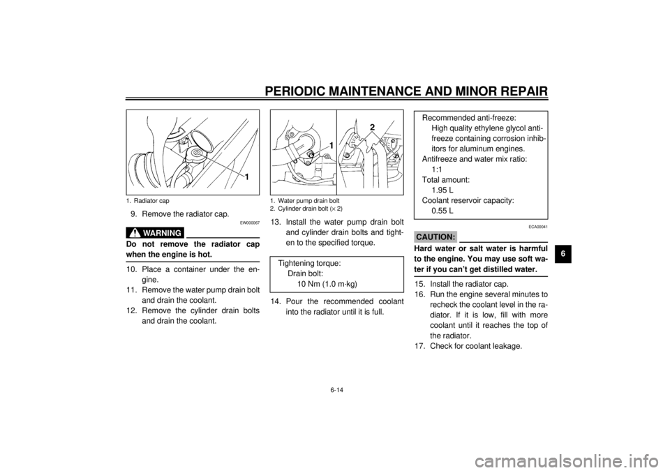
6 9. Remove the radiator cap.
EW000067
WARNING
@ Do not remove the radiator cap
when the engine is hot. @10. Place a container under the en-
gine.
11. Remove the water pump drain bolt
and drain the coolant.
12. Remove the cylinder drain bolts
and drain the coolant.13. Install the water pump drain bolt
and cylinder drain bolts and tight-
en to the specified torque.
14. Pour the recommended coolant
into the radiator until it is full.
ECA00041
CAUTION:@ Hard water or salt water is harmful
to the engine. You may use soft wa-
ter if you can’t get distilled water. @15. Install the radiator cap.
16. Run the engine several minutes to
recheck the coolant level in the ra-
diator. If it is low, fill with more
coolant until it reaches the top of
the radiator.
17. Check for coolant leakage.
1. Radiator cap
1. Water pump drain bolt
2. Cylinder drain bolt (´ 2)
Tightening torque:
Drain bolt:
10 Nm (1.0 m·kg)
Recommended anti-freeze:
High quality ethylene glycol anti-
freeze containing corrosion inhib-
itors for aluminum engines.
Antifreeze and water mix ratio:
1:1
Total amount:
1.95 L
Coolant reservoir capacity:
0.55 L
E_4tv_Periodic.fm Page 14 Wednesday, September 1, 1999 11:12 AM
Page 69 of 109
PERIODIC MAINTENANCE AND MINOR REPAIR
6-19
6
EAU00637
Valve clearance adjustmentThe correct valve clearance changes
with use, resulting in improper fuel/air
supply or engine noise. To prevent this,
the valve clearance must be adjusted
regularly. This adjustment however,
should be left to a professional
Yamaha service technician.
EAU00658
TiresTo ensure maximum performance,
long service and safe operation, note
the following:
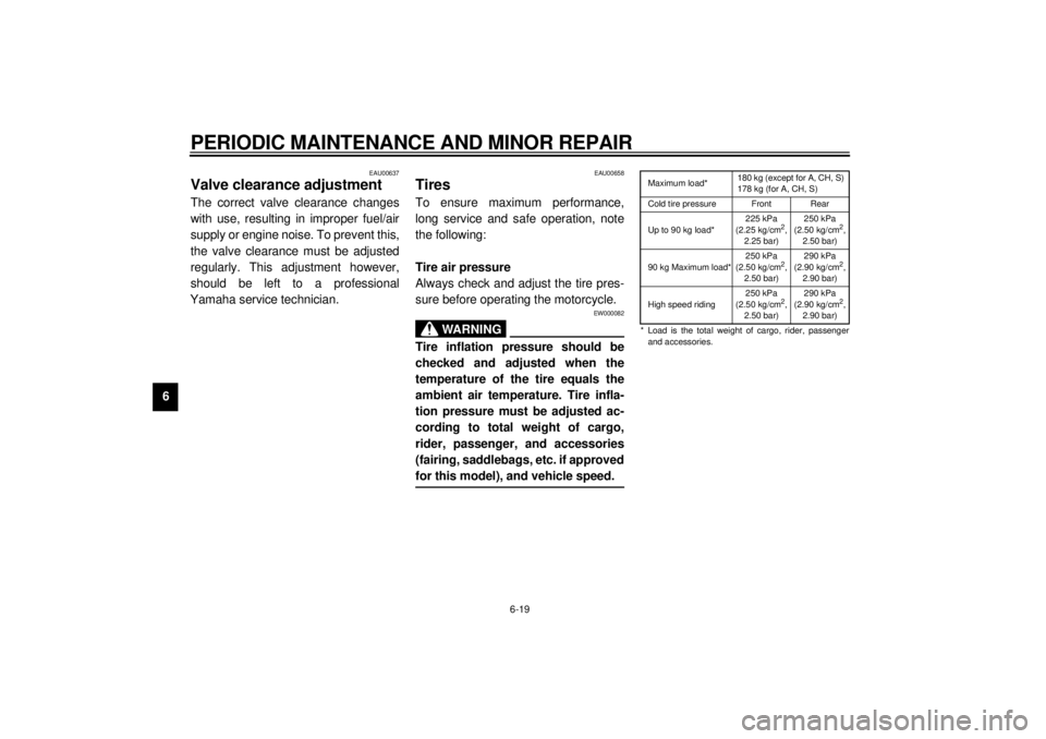
Tire air pressure
Always check and adjust the tire pres-
sure before operating the motorcycle.
EW000082
WARNING
@ Tire inflation pressure should be
checked and adjusted when the
temperature of the tire equals the
ambient air temperature. Tire infla-
tion pressure must be adjusted ac-
cording to total weight of cargo,
rider, passenger, and accessories
(fairing, saddlebags, etc. if approved
for this model), and vehicle speed. @
CE-33EMaximum load*180 kg (except for A, CH, S)
178 kg (for A, CH, S)
Cold tire pressure Front Rear
Up to 90 kg load*225 kPa
(2.25 kg/cm
2,
2.25 bar)250 kPa
(2.50 kg/cm
2,
2.50 bar)
90 kg Maximum load*250 kPa
(2.50 kg/cm
2,
2.50 bar)290 kPa
(2.90 kg/cm
2,
2.90 bar)
High speed riding250 kPa
(2.50 kg/cm
2,
2.50 bar)290 kPa
(2.90 kg/cm
2,
2.90 bar)
* Load is the total weight of cargo, rider, passenger
and accessories.
E_4tv_Periodic.fm Page 19 Wednesday, September 1, 1999 11:12 AM
Page 70 of 109
PERIODIC MAINTENANCE AND MINOR REPAIR
6-20
6
EW000083
WARNING
@ Proper loading of your motorcycle
is important for several characteris-
tics of your motorcycle, such as
handling, braking, performance and
safety. Do not carry loosely packed
items that can shift. Securely pack
your heaviest items close to the
center of the motorcycle, and dis-
tribute the weight evenly from side
to side. Properly adjust the suspen-
sion for your load, and check the
condition and pressure of your tires.
NEVER OVERLOAD YOUR MOTOR-
CYCLE. Make sure the total weight
of the cargo, rider, passenger, and
accessories (fairing, saddlebags,
etc. if approved for this model) does
not exceed the maximum load of the
motorcycle. Operation of an over-
loaded motorcycle could cause tire
damage, an accident, or even injury. @
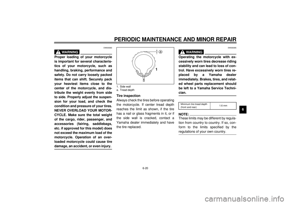
Tire inspection
Always check the tires before operating
the motorcycle. If center tread depth
reaches the limit as shown, if the tire
has a nail or glass fragments in it, or if
the side wall is cracked, contact a
Yamaha dealer immediately and have
the tire replaced.
EW000095
WA R N I N G
@ Operating the motorcycle with ex-
cessively worn tires decrease riding
stability and can lead to loss of con-
trol. Have excessively worn tires re-
placed by a Yamaha dealer
immediately. Brakes, tires, and relat-
ed wheel parts replacement should
be left to a Yamaha Service Techni-
cian. @CE-26ENOTE:@ These limits may be different by regula-
tion from country to country. If so, con-
form to the limits specified by the
regulations of your own country. @
1. Side wall
a. Tread depth
Minimum tire tread depth
(front and rear)1.6 mm
E_4tv_Periodic.fm Page 20 Wednesday, September 1, 1999 11:12 AM
Page 71 of 109
PERIODIC MAINTENANCE AND MINOR REPAIR
6-21
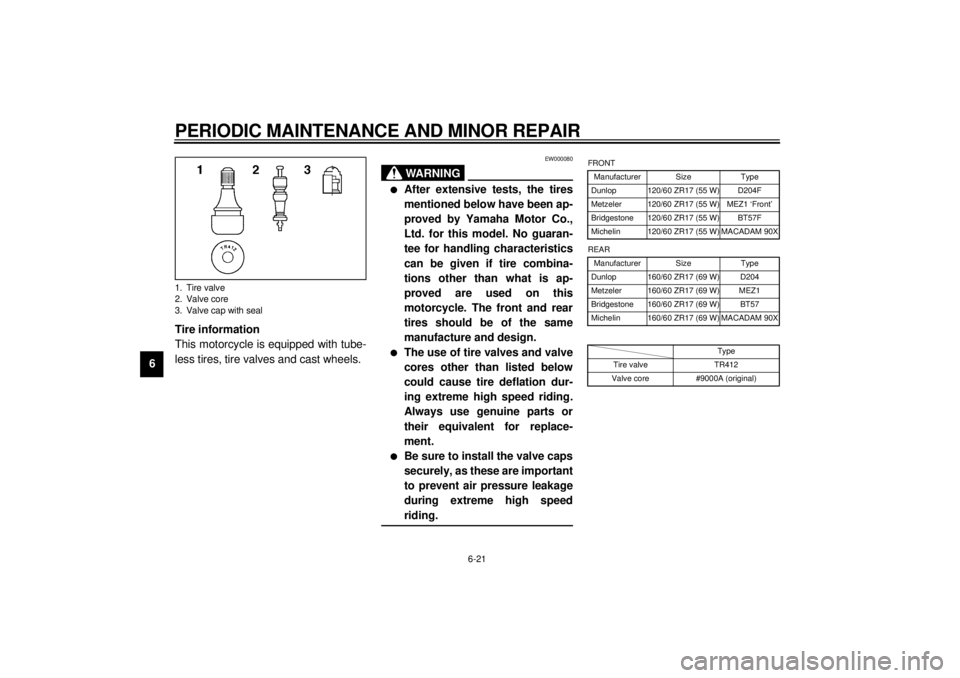
6Tire information
This motorcycle is equipped with tube-
less tires, tire valves and cast wheels.
EW000080
WARNING
@ l
After extensive tests, the tires
mentioned below have been ap-
proved by Yamaha Motor Co.,
Ltd. for this model. No guaran-
tee for handling characteristics
can be given if tire combina-
tions other than what is ap-
proved are used on this
motorcycle. The front and rear
tires should be of the same
manufacture and design.
l
The use of tire valves and valve
cores other than listed below
could cause tire deflation dur-
ing extreme high speed riding.
Always use genuine parts or
their equivalent for replace-
ment.
l
Be sure to install the valve caps
securely, as these are important
to prevent air pressure leakage
during extreme high speed
riding.
@
CE-10E
CE-12E
1. Tire valve
2. Valve core
3. Valve cap with seal
FRONT
Manufacturer Size Type
Dunlop 120/60 ZR17 (55 W) D204F
Metzeler 120/60 ZR17 (55 W) MEZ1 ‘Front’
Bridgestone 120/60 ZR17 (55 W) BT57F
Michelin 120/60 ZR17 (55 W) MACADAM 90X
REAR
Manufacturer Size Type
Dunlop 160/60 ZR17 (69 W) D204
Metzeler 160/60 ZR17 (69 W) MEZ1
Bridgestone 160/60 ZR17 (69 W) BT57
Michelin 160/60 ZR17 (69 W) MACADAM 90X
Type
Tire valve TR412
Valve core #9000A (original)
E_4tv_Periodic.fm Page 21 Wednesday, September 1, 1999 11:12 AM
Page 72 of 109
PERIODIC MAINTENANCE AND MINOR REPAIR
6-22
6
EAU00684
WARNING
@ This motorcycle is fitted with super
high-speed running tires. The fol-
lowing points must be observed in
order for you to make fully effective
use of these tires.l
Never fail to use the specified
tires in tire replacement. Other
tires may have a danger of
bursting at super high-speeds.
l
New tires have a relatively low
grip on the road surface until
they have been slightly worn.
Therefore, approximately 100 km
should be traveled at normal
speed before any high-speed
riding is done.
l
Before any high-speed runs, the
tires should be warmed-up suf-
ficiently.
l
Always inflate to the correct tire
pressure according to the oper-
ating conditions.
@
EAU00687
WheelsTo ensure maximum performance,
long service, and safe operation, note
the following:l
Always inspect the wheels before
a ride. Check for cracks, bends, or
warpage of the wheels. If any ab-
normal condition exists in a wheel,
consult a Yamaha dealer. Do not
attempt even small repairs to the
wheel. If a wheel is deformed or
cracked, it must be replaced.
l
Tires and wheels should be bal-
anced whenever either one is
changed or replaced. Failure to
have a wheel balanced can result
in poor performance, adverse han-
dling characteristics, and short-
ened tire life.
l
Ride at moderate speeds after
changing a tire since the tire sur-
face must first be broken in for it to
develop its optimal characteristics.
E_4tv_Periodic.fm Page 22 Wednesday, September 1, 1999 11:12 AM
Page 74 of 109
PERIODIC MAINTENANCE AND MINOR REPAIR
6-24
6
EW000109
WARNING
@ A soft or spongy feeling in the brake
pedal can indicate the presence of
air in the brake system. This air
must be removed by bleeding the
brake system before the motorcycle
is operated. Air in the system will
cause greatly diminished braking
capability and can result in loss of
control and an accident. Have a
Yamaha dealer inspect and bleed
the system if necessary. @
EAU00713
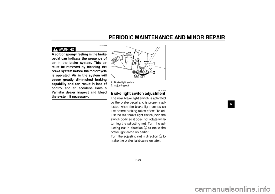
Brake light switch adjustmentThe rear brake light switch is activated
by the brake pedal and is properly ad-
justed when the brake light comes on
just before braking takes effect. To ad-
just the rear brake light switch, hold the
switch body so it does not rotate while
turning the adjusting nut. Turn the ad-
justing nut in direction a
to make the
brake light come on earlier.
Turn the adjusting nut in direction b
to
make the brake light come on later.1. Brake light switch
2. Adjusting nut
E_4tv_Periodic.fm Page 24 Wednesday, September 1, 1999 11:12 AM