2000 YAMAHA YZF1000 ECU
[x] Cancel search: ECUPage 28 of 103

INSTRUMENT AND CONTROL FUNCTIONS
3-14
3
To install
Insert the projection on the front of the
seat into the holder on the frame. Then
push down on the seat.Passenger seat
To remove
Remove the rider seat. Then pull up-
ward on the passenger seat.
To installInsert the projection on the rear of the
seat and the hooks on the front of the
seat into the holders on the frame, and
push the seat backward. Then install
the rider seat.NOTE:@ Make sure that the seats are securely
fitted. @
EAU00264
Helmet holderThe helmet holder is located under the
rider’s seat. Remove the rider’s seat
and hook the helmet on the helmet
holder. Then lock the seat.
EW000030
WA R N I N G
@ Never ride with a helmet in the hel-
met holder. The helmet may hit ob-
jects, causing loss of control and
possibly an accident. @
1. Projection
2. Seat holder
1. Projection
2. Hook (´ 2)
3. Seat holder (´ 3)
1. Helmet holder
E_4sv_Functions.fm Page 14 Tuesday, August 31, 1999 3:42 PM
Page 29 of 103
INSTRUMENT AND CONTROL FUNCTIONS
3-15
3
EAU01688
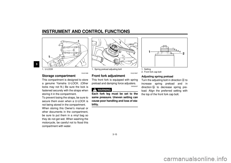
Storage compartmentThis compartment is designed to store
a genuine Yamaha U-LOCK. (Other
locks may not fit.) Be sure the lock is
fastened securely with the straps when
storing it in the compartment.
To prevent losing the straps, be sure to
secure them even when a U-LOCK is
not being stored in the compartment.
When storing this Owner’s manual or
other documents in the compartment,
be sure to put them in a vinyl bag so
they do not get wet. When washing the
motorcycle, be careful not to flood this
compartment with water.
EAU01862*
Front fork adjustmentThis front fork is equipped with spring
preload and damping force adjusters.
EW000037
WARNING
@ Each fork leg must be set to the
same pressure. Uneven setting can
cause poor handling and loss of sta-
bility. @
Adjusting spring preload
Turn the adjusting bolt in direction a
to
increase spring preload and in
directionb
to decrease spring pre-
load. Align the preferred setting with
the top of the front fork cap bolt.
1. U-LOCK
1. Spring preload adjusting bolt
1. Setting
2. Front fork cap bolt
E_4sv_Functions.fm Page 15 Tuesday, August 31, 1999 3:42 PM
Page 65 of 103
PERIODIC MAINTENANCE AND MINOR REPAIR
6-17
6
EW000083
WARNING
@ Proper loading of your motorcycle
is important for several characteris-
tics of your motorcycle, such as
handling, braking, performance and
safety. Do not carry loosely packed
items that can shift. Securely pack
your heaviest items close to the
center of the motorcycle, and dis-
tribute the weight evenly from side
to side. Properly adjust the suspen-
sion for your load, and check the
condition and pressure of your tires.
NEVER OVERLOAD YOUR MOTOR-
CYCLE. Make sure the total weight
of the cargo, rider, passenger, and
accessories (fairing, saddlebags,
etc. if approved for this model) does
not exceed the maximum load of the
motorcycle. Operation of an over-
loaded motorcycle could cause tire
damage, an accident, or even injury. @
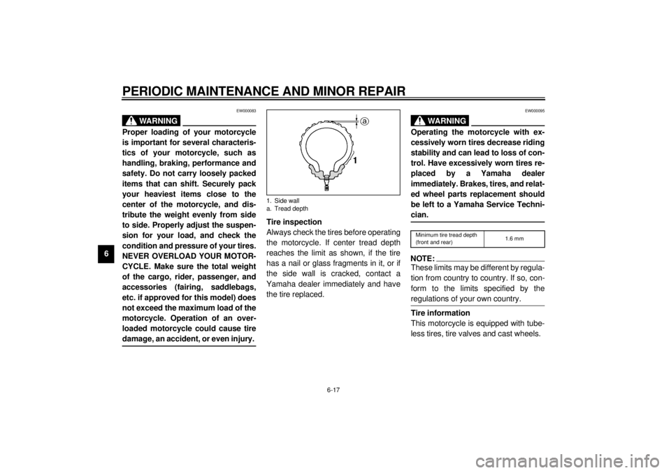
Tire inspection
Always check the tires before operating
the motorcycle. If center tread depth
reaches the limit as shown, if the tire
has a nail or glass fragments in it, or if
the side wall is cracked, contact a
Yamaha dealer immediately and have
the tire replaced.
EW000095
WA R N I N G
@ Operating the motorcycle with ex-
cessively worn tires decrease riding
stability and can lead to loss of con-
trol. Have excessively worn tires re-
placed by a Yamaha dealer
immediately. Brakes, tires, and relat-
ed wheel parts replacement should
be left to a Yamaha Service Techni-
cian. @CE-26ENOTE:@ These limits may be different by regula-
tion from country to country. If so, con-
form to the limits specified by the
regulations of your own country. @Tire information
This motorcycle is equipped with tube-
less tires, tire valves and cast wheels.
1. Side wall
a. Tread depth
Minimum tire tread depth
(front and rear)1.6 mm
E_4sv_Periodic.fm Page 17 Tuesday, August 31, 1999 3:45 PM
Page 66 of 103
PERIODIC MAINTENANCE AND MINOR REPAIR
6-18
6
EW000080
WARNING
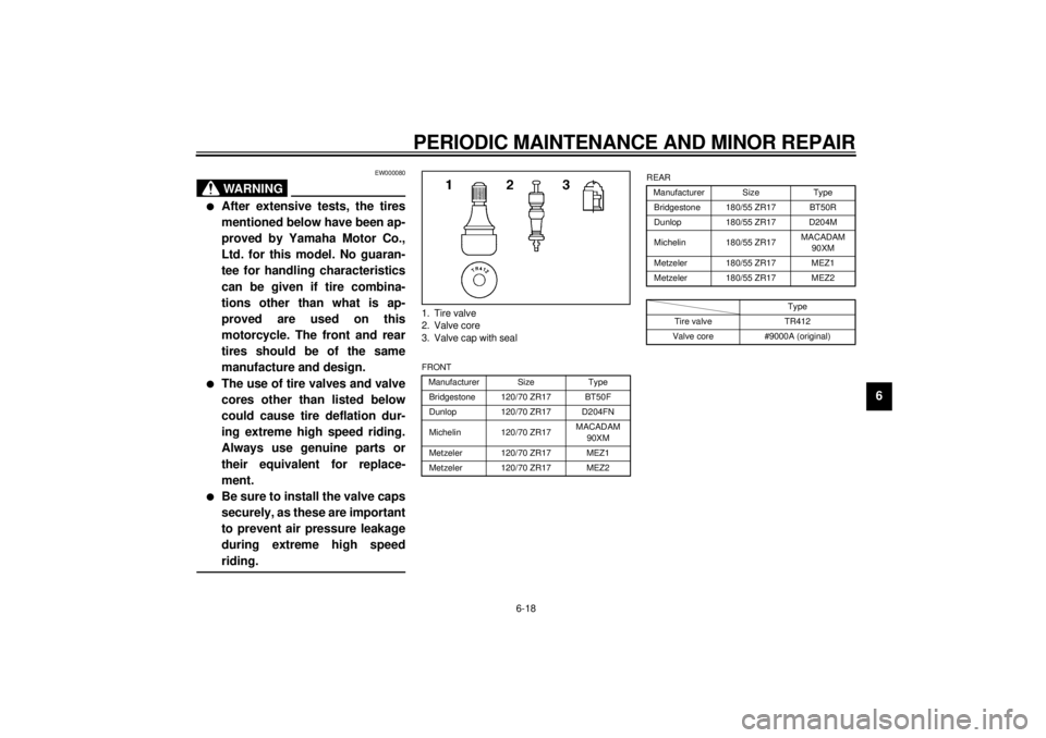
@ l
After extensive tests, the tires
mentioned below have been ap-
proved by Yamaha Motor Co.,
Ltd. for this model. No guaran-
tee for handling characteristics
can be given if tire combina-
tions other than what is ap-
proved are used on this
motorcycle. The front and rear
tires should be of the same
manufacture and design.
l
The use of tire valves and valve
cores other than listed below
could cause tire deflation dur-
ing extreme high speed riding.
Always use genuine parts or
their equivalent for replace-
ment.
l
Be sure to install the valve caps
securely, as these are important
to prevent air pressure leakage
during extreme high speed
riding.
@
CE-10ECE-10E
CE-12E1. Tire valve
2. Valve core
3. Valve cap with sealFRONT
Manufacturer Size Type
Bridgestone 120/70 ZR17 BT50F
Dunlop 120/70 ZR17 D204FN
Michelin 120/70 ZR17MACADAM
90XM
Metzeler 120/70 ZR17 MEZ1
Metzeler 120/70 ZR17 MEZ2
REAR
Manufacturer Size Type
Bridgestone 180/55 ZR17 BT50R
Dunlop 180/55 ZR17 D204M
Michelin 180/55 ZR17MACADAM
90XM
Metzeler 180/55 ZR17 MEZ1
Metzeler 180/55 ZR17 MEZ2
Type
Tire valve TR412
Valve core #9000A (original)
E_4sv_Periodic.fm Page 18 Tuesday, August 31, 1999 3:45 PM
Page 74 of 103

PERIODIC MAINTENANCE AND MINOR REPAIR
6-26
6
EAU02939
Front fork inspectionVisual check
EW000115
WARNING
@ Securely support the motorcycle so
there is no danger of it falling over. @Check for scratches or damage on the
inner tube and excessive oil leakage
from the front fork.
Operation check
1. Place the motorcycle on a level
place.
2. Hold the motorcycle in an upright
position and apply the front brake.
3. Push down hard on the handle-
bars several times and check if the
fork rebounds smoothly.
EC000098
CAUTION:@ If any damage or unsmooth move-
ment is found with the front fork,
consult a Yamaha dealer. @
EAU00794
Steering inspectionPeriodically inspect the condition of the
steering. Worn out or loose steering
bearings may be dangerous. Place a
stand under the engine to raise the
front wheel off the ground. Hold the
lower end of the front forks and try to
move them forward and backward. If
any free play can be felt, ask a Yamaha
dealer to inspect and adjust the steer-
ing. Inspection is easier if the front
wheel is removed.
EW000115
WA R N I N G
@ Securely support the motorcycle so
there is no danger of it falling over. @
E_4sv_Periodic.fm Page 26 Tuesday, August 31, 1999 3:45 PM
Page 77 of 103

PERIODIC MAINTENANCE AND MINOR REPAIR
6-29
6
EAU00827
Headlight bulb replacementThis motorcycle is equipped with a
quartz bulb headlight. If the headlight
bulb burns out, replace the bulb as fol-
lows:
1. Remove the connectors and the
bulb holder cover.2. Unhook the bulb holder and re-
move the defective bulb.
EW000119
WA R N I N G
@ Keep flammable products and your
hands away from a bulb while it is
on, as it is hot. Do not touch a bulb
until it cools down. @3. Put a new bulb into position and
secure it in place with the bulb
holder. Specified fuse:
Main fuse: 30 A
Headlight fuse: 20 A
Signaling system fuse: 15 A
Fan fuse: 7.5 A
Ignition fuse: 15 A
1. Connector
2. Bulb holder cover
1. Bulb holder
E_4sv_Periodic.fm Page 29 Tuesday, August 31, 1999 3:45 PM
Page 79 of 103
PERIODIC MAINTENANCE AND MINOR REPAIR
6-31
6
EAU01252*
Front wheel removal
EW000122
WARNING
@ l
It is advisable to have a Yamaha
dealer service the wheel.
l
Securely support the motor-
cycle so there is no danger of it
falling over.
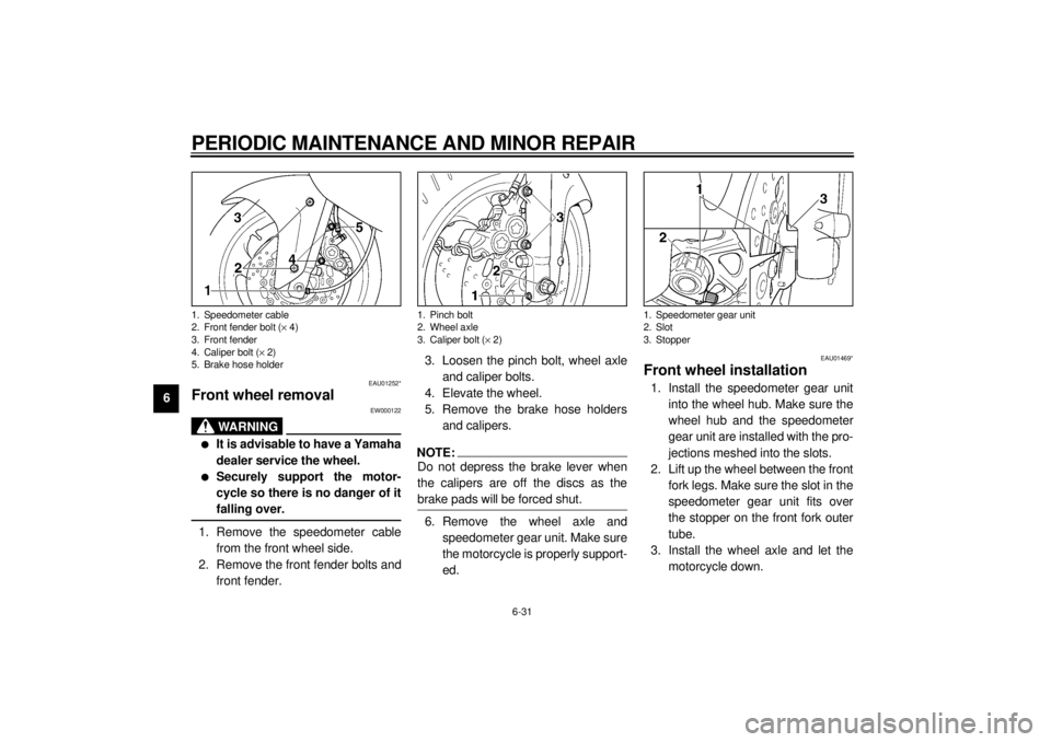
@1. Remove the speedometer cable
from the front wheel side.
2. Remove the front fender bolts and
front fender.3. Loosen the pinch bolt, wheel axle
and caliper bolts.
4. Elevate the wheel.
5. Remove the brake hose holders
and calipers.
NOTE:@ Do not depress the brake lever when
the calipers are off the discs as the
brake pads will be forced shut. @6. Remove the wheel axle and
speedometer gear unit. Make sure
the motorcycle is properly support-
ed.
EAU01469*
Front wheel installation1. Install the speedometer gear unit
into the wheel hub. Make sure the
wheel hub and the speedometer
gear unit are installed with the pro-
jections meshed into the slots.
2. Lift up the wheel between the front
fork legs. Make sure the slot in the
speedometer gear unit fits over
the stopper on the front fork outer
tube.
3. Install the wheel axle and let the
motorcycle down.
1. Speedometer cable
2. Front fender bolt (´ 4)
3. Front fender
4. Caliper bolt (´ 2)
5. Brake hose holder
1. Pinch bolt
2. Wheel axle
3. Caliper bolt (´ 2)
1. Speedometer gear unit
2. Slot
3. Stopper
E_4sv_Periodic.fm Page 31 Tuesday, August 31, 1999 3:45 PM
Page 80 of 103
PERIODIC MAINTENANCE AND MINOR REPAIR
6-32
6 4. Install the calipers, caliper bolts
and brake hose holders. Make
sure there is enough gap between
the brake pads before installing
the calipers onto the brake discs.
5. Tighten the wheel axle, pinch bolt
and caliper bolts to the specified
torques.
6. Push down hard on the handle-
bars several times to check for
proper fork operation.
7. Install the speedometer cable.
8. Install the front fender and bolts.
EAU01247*
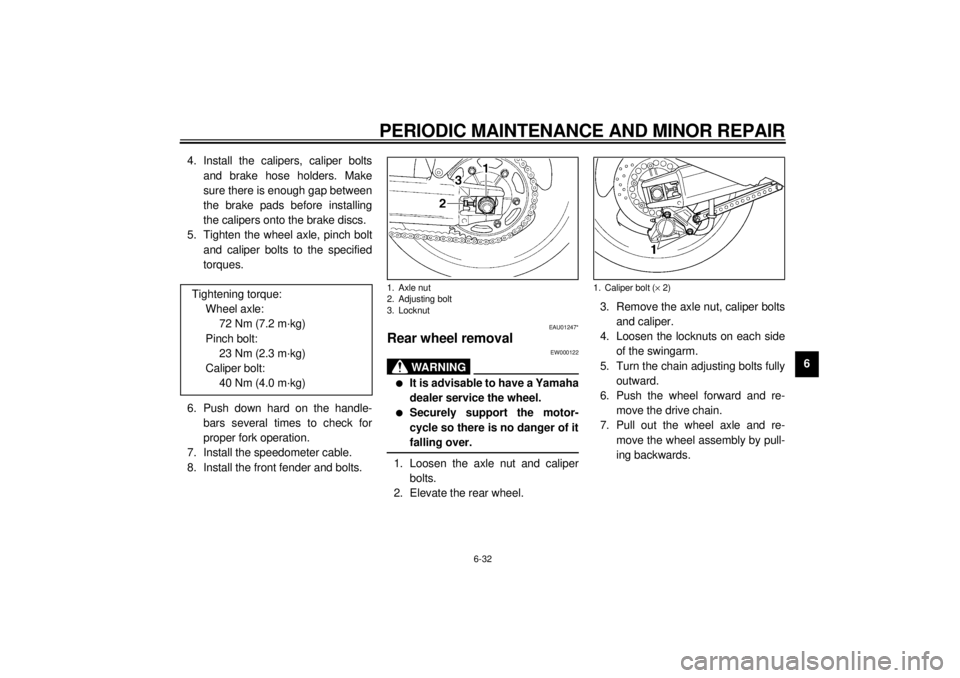
Rear wheel removal
EW000122
WA R N I N G
@ l
It is advisable to have a Yamaha
dealer service the wheel.
l
Securely support the motor-
cycle so there is no danger of it
falling over.
@1. Loosen the axle nut and caliper
bolts.
2. Elevate the rear wheel.3. Remove the axle nut, caliper bolts
and caliper.
4. Loosen the locknuts on each side
of the swingarm.
5. Turn the chain adjusting bolts fully
outward.
6. Push the wheel forward and re-
move the drive chain.
7. Pull out the wheel axle and re-
move the wheel assembly by pull-
ing backwards. Tightening torque:
Wheel axle:
72 Nm (7.2 m·kg)
Pinch bolt:
23 Nm (2.3 m·kg)
Caliper bolt:
40 Nm (4.0 m·kg)1. Axle nut
2. Adjusting bolt
3. Locknut
1. Caliper bolt (´ 2)
E_4sv_Periodic.fm Page 32 Tuesday, August 31, 1999 3:45 PM