Page 296 of 608

4 - 31
ENGVALVES AND VALVE SPRINGS
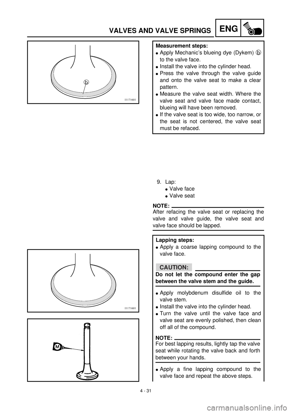
Measurement steps:
lApply Mechanic’s blueing dye (Dykem) b
to the valve face.
lInstall the valve into the cylinder head.
lPress the valve through the valve guide
and onto the valve seat to make a clear
pattern.
lMeasure the valve seat width. Where the
valve seat and valve face made contact,
blueing will have been removed.
lIf the valve seat is too wide, too narrow, or
the seat is not centered, the valve seat
must be refaced.
9. Lap:
lValve face
lValve seat
NOTE:
After refacing the valve seat or replacing the
valve and valve guide, the valve seat and
valve face should be lapped.
Lapping steps:
lApply a coarse lapping compound to the
valve face.
lApply molybdenum disulfide oil to the
valve stem.
lInstall the valve into the cylinder head.
lTurn the valve until the valve face and
valve seat are evenly polished, then clean
off all of the compound.
lApply a fine lapping compound to the
valve face and repeat the above steps.
CAUTION:
Do not let the compound enter the gap
between the valve stem and the guide.
NOTE:
For best lapping results, lightly tap the valve
seat while rotating the valve back and forth
between your hands.
Page 298 of 608

4 - 32
ENGVALVES AND VALVE SPRINGS
lApply Mechanic’s blueing dye (Dykem) to
the valve face.
lInstall the valve into the cylinder head.
lPress the valve through the valve guide
and onto the valve seat to make a clear
pattern.
lMeasure the valve seat width again. If the
valve seat width is out of specification,
reface and relap the valve seat.
NOTE:
After every lapping operation be sure to
clean off all of the compound from the valve
face and valve seat.
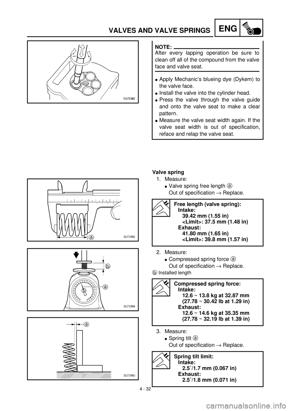
Valve spring
1. Measure:
lValve spring free length a
Out of specification ® Replace.
2. Measure:
lCompressed spring force a
Out of specification ® Replace.
bInstalled length
3. Measure:
lSpring tilt a
Out of specification ® Replace.
Free length (valve spring):
Intake:
39.42 mm (1.55 in)
: 37.5 mm (1.48 in)
Exhaust:
41.80 mm (1.65 in)
: 39.8 mm (1.57 in)
Compressed spring force:
Intake:
12.6 ~ 13.8 kg at 32.87 mm
(27.78 ~ 30.42 lb at 1.29 in)
Exhaust:
12.6 ~ 14.6 kg at 35.35 mm
(27.78 ~ 32.19 lb at 1.39 in)
Spring tilt limit:
Intake:
2.5˚/1.7 mm (0.067 in)
Exhaust:
2.5˚/1.8 mm (0.071 in)
Page 332 of 608
4 - 49
ENG
OIL FILTER, WATER PUMP AND CRANKCASE COVER
(RIGHT)
EC4G3000
REMOVAL POINTS
EC4G3110
Impeller shaft
1. Remove:
lImpeller 1
lPlain washer 2
lImpeller shaft 3
NOTE:
Hold the impeller shaft on its width across the
flats a with spanners, etc. and remove the
impeller.
EC4G3210
Oil seal
NOTE:
It is not necessary to disassemble the water
pump, unless there is an abnormality such as
excessive change in coolant level, discolora-
tion of coolant, or milky transmission oil.
1. Remove:
lBearing 1
2. Remove:
lOil seal 1
EC4G4000
INSPECTION
EC444200
Impeller shaft
1. Inspect:
lImpeller shaft 1
Bend/wear/damage ® Replace.
Fur deposits ® Clean.
Page 336 of 608
4 - 51
ENG
OIL FILTER, WATER PUMP AND CRANKCASE COVER
(RIGHT)
EC4G5220
Impeller shaft
1. Install:
lImpeller shaft 1
lPlain washer 2
lImpeller shaft 3
NOTE:
lTake care so that the oil seal lip is not dam-
aged or the spring does not slip off its posi-
tion.
lWhen installing the impeller shaft, apply the
engine oil on the oil seal lip and impeller
shaft. And install the shaft while turning it.
lHold the impeller shaft on its width across
the flats a with spanners, etc. and remove
the impeller.
Crankcase cover (right)
1. Install:
lDowel pin 1
lO-ring 2
lCollar 3
lGasket 4 New
2. Install:
lCrankcase cover (right) 1
lBolt
NOTE:
lWhen installing the crankcase cover onto the
crankcase, be sure that the impeller shaft
end 2 aligns with the balancer end slot 3.
lTighten the bolts in stage, using a crisscross
pattern.
T R..10 Nm (1.0 m · kg, 7.2 ft · lb)
Page 396 of 608
4 - 81
ENG
CRANKCASE AND CRANKSHAFT
EC4N4101
Crankcase
1. Inspect:
l
Contacting surface
a
Scratches
®
Replace.
l
Engine mounting boss
b
, crankcase
Cracks/damage
®
Replace.
2. Inspect:
l
Bearing
Rotate inner race with a finger.
Rough spot/seizure
®
Replace.
3. Inspect:
l
Oil seal
Wear/damage
®
Replace.
EC4N4201
Crankshaft
1. Measure:
l
Runout limit
a
l
Small end free play limit
b
l
Connecting rod big end side clearance
c
l
Crank width
d
Out of specification
®
Replace.
Use the dial gauge and a thickness
gauge.
Dial gauge and stand:
YU-03097/90890-01252
Standard
Runout
limit:0.03 mm
(0.0012 in)0.05 mm
(0.002 in)
Small end
free play:0.4 ~ 1.0 mm
(0.016 ~ 0.039 in)2.0 mm
(0.08 in)
Side
clearance:0.15 ~ 0.45 mm
(0.0059 ~ 0.0177 in)—
Crack
width:61.95 ~ 62.00 mm
(2.439 ~ 2.441 in)—