Page 51 of 121
AUDIO SYSTEM
4-13
4
Tuning in a radio station automati-
cally
1. Select a frequency band. (See
page 4-12.)
2. Push either side of the up/down
switch once for 1 second or more.
The radio automatically tunes in
the first station that has a strong
enough signal to be received.Tuning in a radio station manually
In order to tune in a particular radio sta-
tion (e.g., when the signal is too weak
for automatic tuning), the radio fre-
quency can be selected manually as
follows.
1. Select a frequency band. (See
page 4-12.)
2. Repeatedly push the “SELECT”
button for less than 1 second until
the currently selected radio fre-
quency appears in the display.3. Push either side of the up/down
switch for less than 1 second until
the desired frequency is dis-
played. The frequency changes
in 0.2-MHz steps for FM and in
10-kHz steps for AM.
E_5jc_Audio.fm Page 13 Saturday, October 16, 1999 1:09 PM
Page 52 of 121

AUDIO SYSTEM
4-14
4
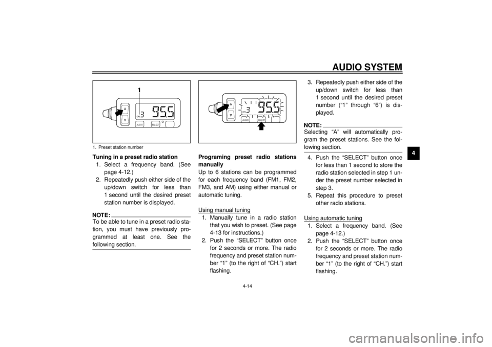
Tuning in a preset radio station
1. Select a frequency band. (See
page 4-12.)
2. Repeatedly push either side of the
up/down switch for less than
1 second until the desired preset
station number is displayed.
NOTE:@ To be able to tune in a preset radio sta-
tion, you must have previously pro-
grammed at least one. See the
following section. @
Programing preset radio stations
manually
Up to 6 stations can be programmed
for each frequency band (FM1, FM2,
FM3, and AM) using either manual or
automatic tuning.
Using manual tuning1. Manually tune in a radio station
that you wish to preset. (See page
4-13 for instructions.)
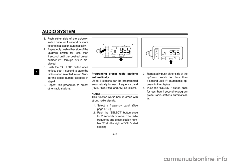
2. Push the “SELECT” button once
for 2 seconds or more. The radio
frequency and preset station num-
ber “1” (to the right of “CH.”) start
flashing.3. Repeatedly push either side of the
up/down switch for less than
1 second until the desired preset
number (“1” through “6”) is dis-
played.
NOTE:@ Selecting “A” will automatically pro-
gram the preset stations. See the fol-
lowing section. @4. Push the “SELECT” button once
for less than 1 second to store the
radio station selected in step 1 un-
der the preset number selected in
step 3.
5. Repeat this procedure to preset
other radio stations.
Using automatic tuning1. Select a frequency band. (See
page 4-12.)
2. Push the “SELECT” button once
for 2 seconds or more. The radio
frequency and preset station num-
ber “1” (to the right of “CH.”) start
flashing.
1. Preset station number
E_5jc_Audio.fm Page 14 Saturday, October 16, 1999 1:09 PM
Page 53 of 121

AUDIO SYSTEM
4-15
43. Push either side of the up/down
switch once for 1 second or more
to tune in a station automatically.
4. Repeatedly push either side of the
up/down switch for less than
1 second until the desired preset
number (“1” through “6”) is dis-
played.
5. Push the “SELECT” button once
for less than 1 second to store the
radio station selected in step 3 un-
der the preset number selected in
step 4.
6. Repeat this procedure to preset
other radio stations.Programing preset radio stations
automatically
Up to 6 stations can be programmed
automatically for each frequency band
(FM1, FM2, FM3, and AM) as follows.
NOTE:@ This function works best in areas with
strong radio signals. @1. Select a frequency band. (See
page 4-12.)
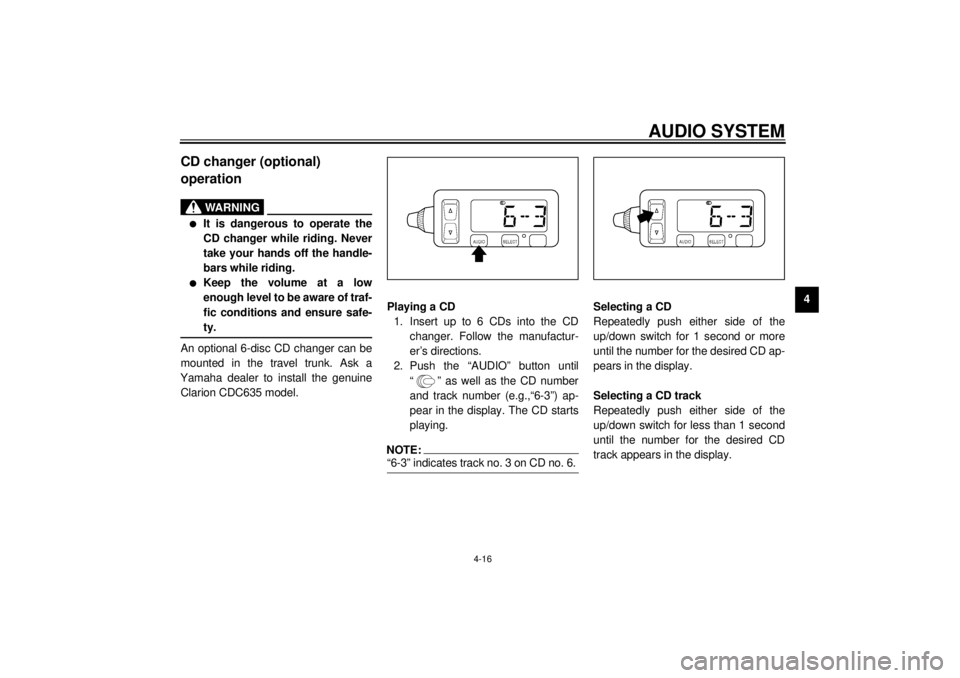
2. Push the “SELECT” button once
for 2 seconds or more. The radio
frequency and preset station num-
ber “1” (to the right of “CH.”) start
flashing.3. Repeatedly push either side of the
up/down switch for less than
1 second until “A” (automatic) ap-
pears in the display.
4. Push the “SELECT” button once
for less than 1 second to program
preset radio stations automatical-
ly.
E_5jc_Audio.fm Page 15 Saturday, October 16, 1999 1:09 PM
Page 54 of 121

AUDIO SYSTEM
4-16
4
CD changer (optional)
operation
WARNING
@ l
It is dangerous to operate the
CD changer while riding. Never
take your hands off the handle-
bars while riding.
l
Keep the volume at a low
enough level to be aware of traf-
fic conditions and ensure safe-
ty.
@An optional 6-disc CD changer can be
mounted in the travel trunk. Ask a
Yamaha dealer to install the genuine
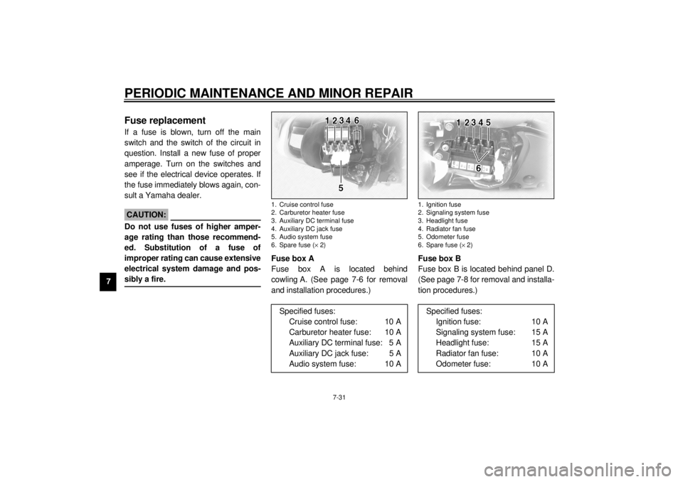
Clarion CDC635 model.Playing a CD
1. Insert up to 6 CDs into the CD
changer. Follow the manufactur-
er’s directions.
2. Push the “AUDIO” button until
“ ” as well as the CD number
and track number (e.g.,“6-3”) ap-
pear in the display. The CD starts
playing.
NOTE:@ “6-3” indicates track no. 3 on CD no. 6. @
Selecting a CD
Repeatedly push either side of the
up/down switch for 1 second or more
until the number for the desired CD ap-
pears in the display.
Selecting a CD track
Repeatedly push either side of the
up/down switch for less than 1 second
until the number for the desired CD
track appears in the display.
E_5jc_Audio.fm Page 16 Saturday, October 16, 1999 1:09 PM
Page 55 of 121
AUDIO SYSTEM
4-17
4
Auxiliary audio source
operationAuxiliary audio equipment can be con-
nected to, and played through, the au-
dio system.
1. Insert the output plug of the auxil-
iary equipment into the jack locat-
ed at the right of the cassette
deck.2. Repeatedly push the “AUDIO” but-
ton for less than 1 second until
“AUX” appears in the display. The
auxiliary equipment can now be
played through the audio system.1. Auxiliary audio input jackE_5jc_Audio.fm Page 17 Saturday, October 16, 1999 1:09 PM
Page 97 of 121

PERIODIC MAINTENANCE AND MINOR REPAIR
7-31
7
EAU01801
Fuse replacementIf a fuse is blown, turn off the main
switch and the switch of the circuit in
question. Install a new fuse of proper
amperage. Turn on the switches and
see if the electrical device operates. If
the fuse immediately blows again, con-
sult a Yamaha dealer.
EC000103
CAUTION:@ Do not use fuses of higher amper-
age rating than those recommend-
ed. Substitution of a fuse of
improper rating can cause extensive
electrical system damage and pos-
sibly a fire. @
Fuse box A
Fuse box A is located behind
cowling A. (See page 7-6 for removal
and installation procedures.)Fuse box B
Fuse box B is located behind panel D.
(See page 7-8 for removal and installa-
tion procedures.)1. Cruise control fuse
2. Carburetor heater fuse
3. Auxiliary DC terminal fuse
4. Auxiliary DC jack fuse
5. Audio system fuse
6. Spare fuse (´ 2)
Specified fuses:
Cruise control fuse: 10 A
Carburetor heater fuse: 10 A
Auxiliary DC terminal fuse: 5 A
Auxiliary DC jack fuse: 5 A
Audio system fuse: 10 A
1. Ignition fuse
2. Signaling system fuse
3. Headlight fuse
4. Radiator fan fuse
5. Odometer fuse
6. Spare fuse (´ 2)
Specified fuses:
Ignition fuse: 10 A
Signaling system fuse: 15 A
Headlight fuse: 15 A
Radiator fan fuse: 10 A
Odometer fuse: 10 A
E_5jc_Periodic.fm Page 31 Saturday, October 16, 1999 1:10 PM
Page 106 of 121

MOTORCYCLE CARE AND STORAGE
8-2
8
ECA00036
CAUTION:@ l
Avoid using strong acidic wheel
cleaners, especially on spoked
wheels. If you do use such
products for hard-to-remove
dirt, do not leave it on any long-
er than instructed, then thor-
oughly rinse it off with water,
immediately dry the area and
apply a corrosion protection
spray.
l
Improper cleaning can damage
windshields, cowlings, panels
and other plastic parts. Use
only a soft, clean cloth or
sponge with mild detergent and
water to clean plastic.
l
Do not use any harsh chemical
products on plastic parts. Be
sure to avoid using cloths or
sponges which have been in
contact with strong or abrasive
cleaning products, solvent or
thinner, fuel (gasoline), rust re-
movers or inhibitors, brake flu-
id, antifreeze or electrolyte.
l
Do not use high-pressure wash-
ers or steam-jet cleaners since
they cause water seepage and
deterioration in the following ar-
eas: seals (of wheel bearings,
swingarm bearings, forks and
brakes), electric components
(couplers, connectors, instru-
ments, switches, lights, audio
system and speakers), saddle-
bags, travel trunk, breather hos-
es and vents.
l
For motorcycles equipped with
a windshield: Do not use strong
cleaners or hard sponges as
they will cause dulling or
scratching. Some cleaning
compounds for plastic may
leave scratches on the wind-
shield. Test the product on a
small hidden part of the wind-
shield to make sure they do not
leave any marks. If the wind-
shield is scratched, use a quali-
ty plastic polishing compound
after washing.
@
E_5jc_Cleaning.fm Page 2 Saturday, October 16, 1999 1:12 PM
Page 114 of 121

SPECIFICATIONS
9-4
9
Headlight typeQuar tz bulb (halogen)
Bulb voltage, wattage ´ quantity
Headlight 12 V, 60/55 W ´ 1
Tail/brake light 12 V, 5/21 W ´ 1
Turn signal light 12 V, 21 W ´ 4
Auxiliary light 12 V, 4 W ´ 1
Licence light 12 V, 5 W ´ 2
Neutral indicator light 12 V, 1.7 W ´ 1
High beam indicator light 12 V, 1.7 W ´ 1
Oil level indicator light 12 V, 1.7 W ´ 1
Turn indicator light 12 V, 1.7 W ´ 2
Fuel level indicator light 14 V, 3 W ´ 1
Coolant temperature indicator
light 12 V, 1.7 W ´ 1
Engine trouble indicator light 12 V, 1.7 W ´ 1
Overdrive indicator light 12 V, 1.7 W ´ 1
Cruise control “SET” indicator
light 12 V, 1.7 W ´ 1
Cruise control “RES” indicator
light 12 V, 1.7 W ´ 1
Cruise control “ON” indicator
light 12 V, 1.7 W ´ 1Audio system amplifier
Output power
Speaker 14 W ´ 4
Headset 1 W ´ 2
Auto-volume range 5 steps
Output impedance
Speaker 4 W
Headset 8 W ~ 16 W
Fuses
Main fuse 30 A
Headlight fuse 15 A
Signaling system fuse 15 A
Ignition fuse 10 A
Radiator fan fuse 10 A
Odometer fuse 10 A
Cruise control fuse 10 A
Carburetor heater fuse 10 A
Audio system fuse 10 A
Auxiliary DC jack fuse 5 A
Auxiliary DC terminal fuse 5 A
E_5jc_Spec.fm Page 4 Saturday, October 16, 1999 1:12 PM