2000 YAMAHA XV1600A torque
[x] Cancel search: torquePage 29 of 95
INSTRUMENT AND CONTROL FUNCTIONS
3-15
33. Tighten the locknut to the speci-
fied torque.
EC000018
CAUTION:@ Always tighten the locknut against
the spring adjusting nut and tighten
the locknut to the specified torque. @
EAU00315
WARNING
@ This shock absorber contains high-
ly pressurized nitrogen gas. Read
and understand the following infor-
mation before handling the shock
absorber. The manufacturer cannot
be held responsible for property
damage or personal injury that may
result from improper handling.l
Do not tamper with or attempt to
open the cylinder assembly.
l
Do not subject the shock ab-
sorber to an open flame or other
high heat source. This may
cause the unit to explode due to
excessive gas pressure.
l
Do not deform or damage the
cylinder in any way. Cylinder
damage will result in poor
damping performance.
l
Take your shock absorber to a
Yamaha dealer for any service.
@
EAU00330
SidestandThis model is equipped with an ignition
circuit cut-off system. The motorcycle
must not be ridden when the sidestand
is down. The sidestand is located on
the left side of the frame. (Refer to
page 5-1 for an explanation of this sys-
tem.)
EW000044
WARNING
@ This motorcycle must not be operat-
ed with the sidestand in the down
position. If the stand is not properly
retracted, it could contact the
ground and distract the operator, re-
sulting in a possible loss of control.
Yamaha has designed into this
motorcycle a lockout system to as-
sist the operator in fulfilling the re-
sponsibility of retracting the
sidestand. Please check carefully
the operating instructions listed be-
low and if there is any indication of a
malfunction, return the motorcycle
to a Yamaha dealer immediately for
repair. @
Tightening torque:
Locknut:
35 Nm (3.5 m·kg)
E_5ja_Functions.fm Page 15 Saturday, October 16, 1999 10:10 AM
Page 45 of 95
6-1
6
EAU00462
6-PERIODIC MAINTENANCE AND MINOR REPAIR
EAU00464
Periodic inspection, adjustment and lu-
brication will keep your motorcycle in
the safest and most efficient condition
possible. Safety is an obligation of the
motorcycle owner. The maintenance
and lubrication schedule chart should
be considered strictly as a guide to
general maintenance and lubrication
intervals. YOU MUST TAKE INTO
CONSIDERATION THAT WEATHER,
TERRAIN, GEOGRAPHICAL LOCA-
TIONS, AND A VARIETY OF INDIVID-
UAL USES ALL TEND TO DEMAND
THAT EACH OWNER ALTER THIS
TIME SCHEDULE TO SHORTER IN-
TERVALS TO MATCH THE ENVI-RONMENT. The most important points
of motorcycle inspection, adjustment,
and lubrication are explained in the fol-
lowing pages.
EW000060
WARNING
@ If you are not familiar with motor-
cycle service, this work should be
done by a Yamaha dealer. @
EAU01826
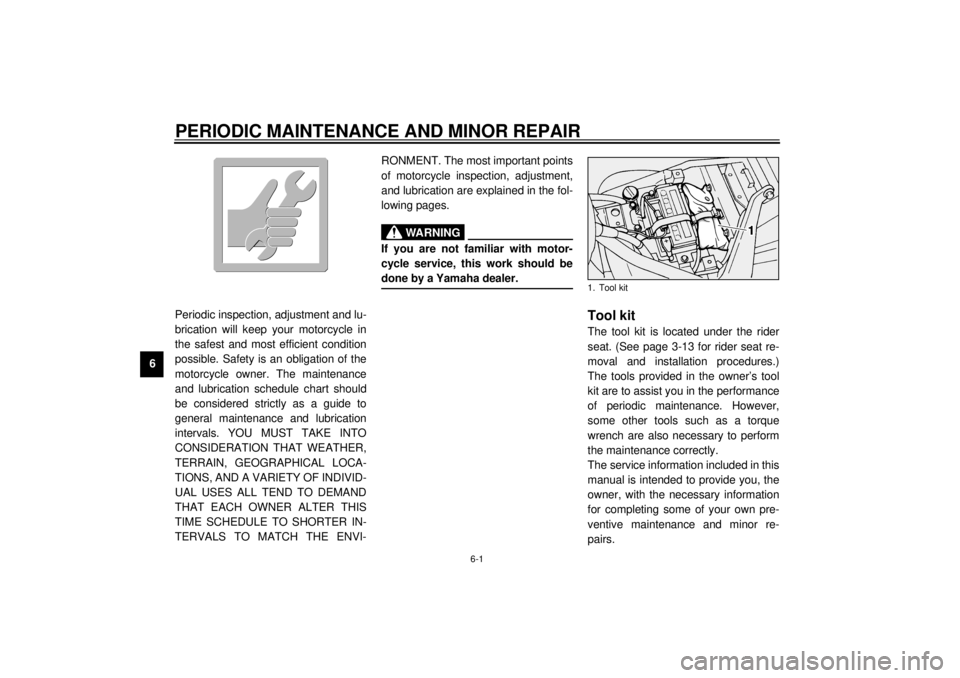
Tool kitThe tool kit is located under the rider
seat. (See page 3-13 for rider seat re-
moval and installation procedures.)
The tools provided in the owner’s tool
kit are to assist you in the performance
of periodic maintenance. However,
some other tools such as a torque
wrench are also necessary to perform
the maintenance correctly.
The service information included in this
manual is intended to provide you, the
owner, with the necessary information
for completing some of your own pre-
ventive maintenance and minor re-
pairs.1. Tool kit
E_5ja_Periodic.fm Page 1 Saturday, October 16, 1999 10:12 AM
Page 50 of 95

PERIODIC MAINTENANCE AND MINOR REPAIR
6-6
6
EAU01639
Spark plug inspectionThe spark plug is an important engine
component and should be inspected
periodically, preferably by a Yamaha
dealer. The condition of the spark plug
can indicate the condition of the en-
gine.
Normally, all spark plugs from the
same engine should have the same
color on the white insulator around the
center electrode. The ideal color at this
point is a medium-to-light tan color for a
motorcycle that is being ridden normal-
ly. If one spark plug shows a distinctly
different color, there could be some-
thing wrong with the engine.Do not attempt to diagnose such prob-
lems yourself. Instead, take the motor-
cycle to a Yamaha dealer. The spark
plugs should be periodically removed
and inspected because heat and de-
posits will cause any spark plug to
slowly break down and erode. If elec-
trode erosion becomes excessive, or if
carbon and other deposits are exces-
sive, the spark plug should be replaced
with the specified plug.
Before installing any spark plug, mea-
sure the electrode gap with a wire
thickness gauge and adjust it to specifi-
cation.When installing a spark plug, the gas-
ket surface should always be cleaned
and a new gasket used. Any grime
should be wiped off from the threads
and the spark plug tightened to the
specified torque.
NOTE:@ If a torque wrench is not available when
installing a spark plug, a good estimate
of the correct torque is 1/4 to 1/2 turn
past finger tight. The spark plug should
be tightened to the specified torque as
soon as possible. @
a. Spark plug gap
Specified spark plug:
DPR7EA-9/NGK or
X22EPR-U9/DENSO
Spark plug gap:
0.8 ~ 0.9 mm
Tightening torque:
Spark plug:
17.5 Nm (1.75 m·kg)
E_5ja_Periodic.fm Page 6 Saturday, October 16, 1999 10:12 AM
Page 53 of 95
PERIODIC MAINTENANCE AND MINOR REPAIR
6-9
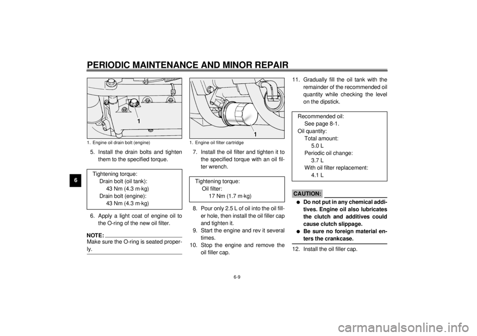
65. Install the drain bolts and tighten
them to the specified torque.
6. Apply a light coat of engine oil to
the O-ring of the new oil filter.
NOTE:@ Make sure the O-ring is seated proper-
ly. @
7. Install the oil filter and tighten it to
the specified torque with an oil fil-
ter wrench.
8. Pour only 2.5 L of oil into the oil fill-
er hole, then install the oil filler cap
and tighten it.
9. Start the engine and rev it several
times.
10. Stop the engine and remove the
oil filler cap.11. Gradually fill the oil tank with the
remainder of the recommended oil
quantity while checking the level
on the dipstick.
EC000066
CAUTION:@ l
Do not put in any chemical addi-
tives. Engine oil also lubricates
the clutch and additives could
cause clutch slippage.
l
Be sure no foreign material en-
ters the crankcase.
@12. Install the oil filler cap.
1. Engine oil drain bolt (engine)Tightening torque:
Drain bolt (oil tank):
43 Nm (4.3 m·kg)
Drain bolt (engine):
43 Nm (4.3 m·kg)
1. Engine oil filter cartridge
Tightening torque:
Oil filter:
17 Nm (1.7 m·kg)
Recommended oil:
See page 8-1.
Oil quantity:
Total amount:
5.0 L
Periodic oil change:
3.7 L
With oil filter replacement:
4.1 L
E_5ja_Periodic.fm Page 9 Saturday, October 16, 1999 10:12 AM
Page 54 of 95
PERIODIC MAINTENANCE AND MINOR REPAIR
6-10
6 13. Start the engine and warm it up for
several minutes. While warming
up, check for oil leakage. If oil
leakage is found, stop the engine
immediately and check for the
cause.
14. Stop the engine and recheck the
oil level.
EAU01828
Transfer case oilOil level inspection
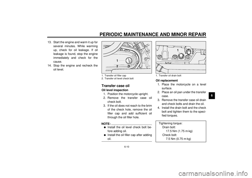
1. Position the motorcycle upright.
2. Remove the transfer case oil
check bolt.
3. If the oil does not reach to the brim
of the check hole, remove the oil
filler cap and add sufficient oil
through the oil filler hole.NOTE:@ l
Install the oil level check bolt be-
fore adding oil.
l
Install the oil filler cap after adding
oil.
@
Oil replacement
1. Place the motorcycle on a level
surface.
2. Place an oil pan under the transfer
case.
3. Remove the transfer case oil drain
and check bolts and drain the oil.
4. Install the drain bolt and the check
bolt and tighten them to the speci-
fied torques.
1. Transfer oil filler cap
2. Transfer oil level check bolt
1. Transfer oil drain boltTightening torque:
Drain bolt:
17.5 Nm (1.75 m·kg)
Check bolt:
7.5 Nm (0.75 m·kg)
E_5ja_Periodic.fm Page 10 Saturday, October 16, 1999 10:12 AM
Page 67 of 95
PERIODIC MAINTENANCE AND MINOR REPAIR
6-23
6
EAU01748
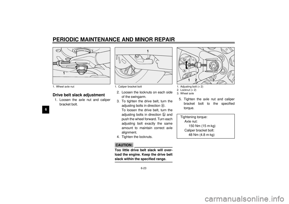
Drive belt slack adjustment1. Loosen the axle nut and caliper
bracket bolt.2. Loosen the locknuts on each side
of the swingarm.
3. To tighten the drive belt, turn the
adjusting bolts in direction
a.
To loosen the drive belt, turn the
adjusting bolts in direction
b and
push the wheel forward. Turn each
adjusting bolt exactly the same
amount to maintain correct axle
alignment.
4. Tighten the locknuts.
ECA00025
CAUTION:@ Too little drive belt slack will over-
load the engine. Keep the drive belt
slack within the specified range. @
5. Tighten the axle nut and caliper
bracket bolt to the specified
torque.
1. Wheel axle nut
1. Caliper bracket bolt
1. Adjusting bolt (´ 2)
2. Locknut (´ 2)
3. Wheel axle
Tightening torque:
Axle nut:
150 Nm (15 m·kg)
Caliper bracket bolt:
48 Nm (4.8 m·kg)
E_5ja_Periodic.fm Page 23 Saturday, October 16, 1999 10:12 AM
Page 89 of 95
SPECIFICATIONS
8-5
8
EAU01064
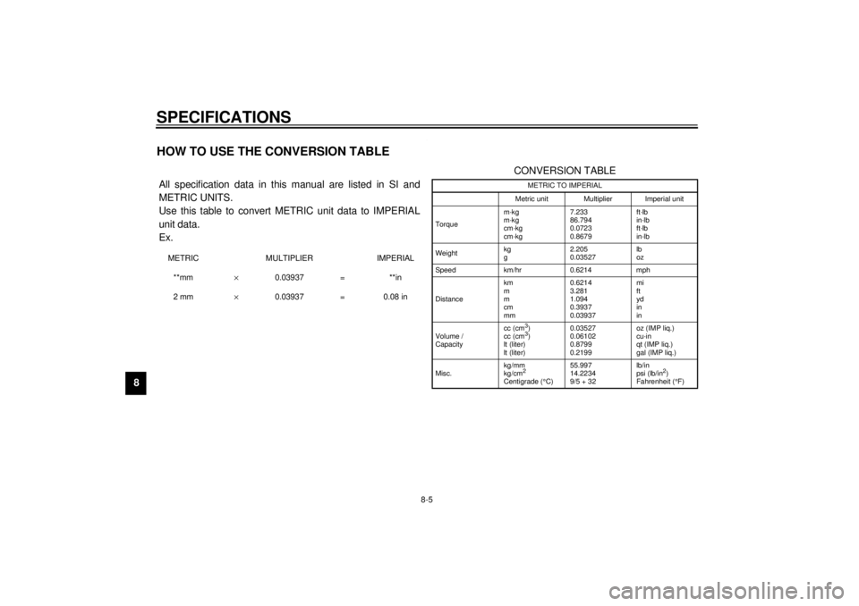
HOW TO USE THE CONVERSION TABLECS-02E All specification data in this manual are listed in SI and
METRIC UNITS.
Use this table to convert METRIC unit data to IMPERIAL
unit data.
Ex.METRIC MULTIPLIER IMPERIAL
**mm´ 0.03937 = **in
2 mm´ 0.03937 = 0.08 in
CONVERSION TABLE
METRIC TO IMPERIAL
Metric unit Multiplier Imperial unit
Torquem·kg
m·kg
cm·kg
cm·kg7.233
86.794
0.0723
0.8679ft·lb
in·lb
ft·lb
in·lb
Weightkg
g2.205
0.03527lb
oz
Speed km/hr 0.6214 mph
Distancekm
m
m
cm
mm0.6214
3.281
1.094
0.3937
0.03937mi
ft
yd
in
in
Volume /
Capacitycc (cm3)
cc (cm3)
lt (liter)
lt (liter)0.03527
0.06102
0.8799
0.2199oz (IMP liq.)
cu·in
qt (IMP liq.)
gal (IMP liq.)
Misc.kg/mm
kg/cm2
Centigrade (°
C)55.997
14.2234
9/5 + 32 lb/in
psi (lb/in
2)
Fahrenheit (°
F)
E_5ja_Spec.fm Page 5 Saturday, October 16, 1999 10:18 AM