Page 3 of 95

EAU00005
IMPORTANT MANUAL INFORMATIONParticularly important information is distinguished in this manual by the following notations:
The Safety Alert Symbol means ATTENTION! BECOME ALERT! YOUR SAFETY IS
INVOLVED!
WARNING
Failure to follow WARNING instructions could result in severe injury or death
to the
motorcycle operator, a bystander or a person inspecting or repairing the motorcycle.
CAUTION:A CAUTION indicates special precautions that must be taken to avoid damage to the
motorcycle.NOTE:
A NOTE provides key information to make procedures easier or clearer.
NOTE:@ l
This manual should be considered a permanent part of this motorcycle and should remain
with it even if the motorcycle is subsequently sold.
l
Yamaha continually seeks advancements in product design and quality. Therefore, while
this manual contains the most current product information available at the time of printing,
there may be minor discrepancies between your motorcycle and this manual. If there is any
question concerning this manual, please consult your Yamaha dealer.
@
E_5ja_Info0.fm Page 1 Saturday, October 16, 1999 10:09 AM
Page 4 of 95
IMPORTANT MANUAL INFORMATION
EW000002
WARNING
@ PLEASE READ THIS MANUAL CAREFULLY AND COMPLETELY BEFORE OPERATING
THIS MOTORCYCLE. @
E_5ja_Info0.fm Page 2 Saturday, October 16, 1999 10:09 AM
Page 15 of 95

3-1
3
EAU00027
3-INSTRUMENT AND CONTROL FUNCTIONS
EAU00029*
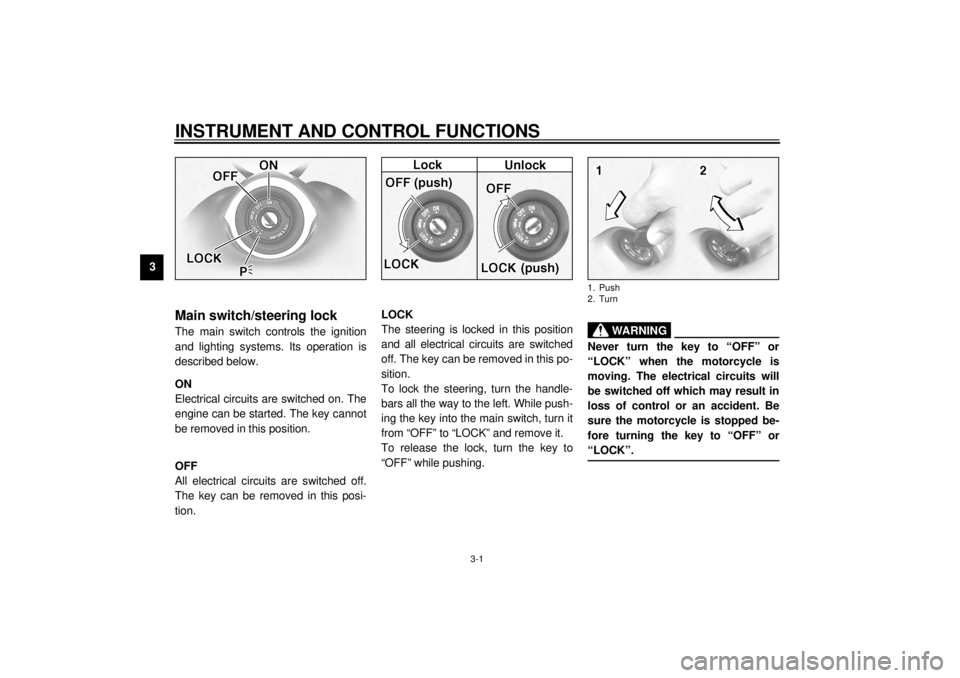
Main switch/steering lockThe main switch controls the ignition
and lighting systems. Its operation is
described below.
EAU00036
ON
Electrical circuits are switched on. The
engine can be started. The key cannot
be removed in this position.
EAU00038
OFF
All electrical circuits are switched off.
The key can be removed in this posi-
tion.
EAU00040
LOCK
The steering is locked in this position
and all electrical circuits are switched
off. The key can be removed in this po-
sition.
To lock the steering, turn the handle-
bars all the way to the left. While push-
ing the key into the main switch, turn it
from “OFF” to “LOCK” and remove it.
To release the lock, turn the key to
“OFF” while pushing.
EW000016
WARNING
@ Never turn the key to “OFF” or
“LOCK” when the motorcycle is
moving. The electrical circuits will
be switched off which may result in
loss of control or an accident. Be
sure the motorcycle is stopped be-
fore turning the key to “OFF” or
“LOCK”. @1. Push
2. Turn
E_5ja_Functions.fm Page 1 Saturday, October 16, 1999 10:10 AM
Page 23 of 95

INSTRUMENT AND CONTROL FUNCTIONS
3-9
3
EAU02917
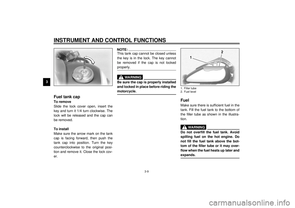
Fuel tank capTo remove
Slide the lock cover open, insert the
key and turn it 1/4 turn clockwise. The
lock will be released and the cap can
be removed.
To install
Make sure the arrow mark on the tank
cap is facing forward, then push the
tank cap into position. Turn the key
counterclockwise to the original posi-
tion and remove it. Close the lock cov-
er.
NOTE:@ This tank cap cannot be closed unless
the key is in the lock. The key cannot
be removed if the cap is not locked
properly. @
EW000023
WARNING
@ Be sure the cap is properly installed
and locked in place before riding the
motorcycle. @
EAU01183
FuelMake sure there is sufficient fuel in the
tank. Fill the fuel tank to the bottom of
the filler tube as shown in the illustra-
tion.
EW000130
WARNING
@ Do not overfill the fuel tank. Avoid
spilling fuel on the hot engine. Do
not fill the fuel tank above the bot-
tom of the filler tube or it may over-
flow when the fuel heats up later and
expands. @1. Filler tube
2. Fuel level
E_5ja_Functions.fm Page 9 Saturday, October 16, 1999 10:10 AM
Page 27 of 95
INSTRUMENT AND CONTROL FUNCTIONS
3-13
3
EAU01737
Rider seatTo remove
Insert the key into the main switch and
turn it counterclockwise to the “OPEN”
position. Then, remove the seat by pull-
ing it upward.NOTE:@ Do not push inward when turning the
key. @
To install
Insert the projection on the rear of the
seat into the holder, then push the front
of the seat downward until it locks and
remove the key from the main switch.NOTE:@ Make sure the seat is securely installed
before riding the motorcycle. @
EAU01819*
Helmet holderThe helmet holder is located under the
rider seat.
Remove the rider seat and hook the
helmet on the helmet holder. Then, in-
stall the seat.
EW000030
WARNING
@ Never ride with a helmet in the hel-
met holder. The helmet may hit ob-
jects, causing loss of control and
possibly an accident. @
1. Projection
2. Seat holder
1. Helmet holder
E_5ja_Functions.fm Page 13 Saturday, October 16, 1999 10:10 AM
Page 29 of 95

INSTRUMENT AND CONTROL FUNCTIONS
3-15
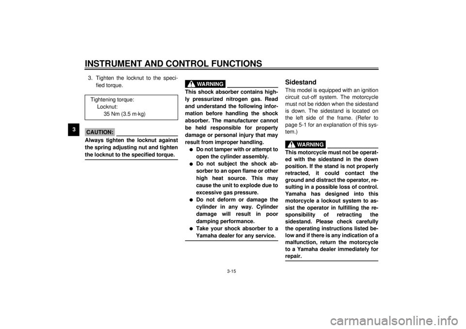
33. Tighten the locknut to the speci-
fied torque.
EC000018
CAUTION:@ Always tighten the locknut against
the spring adjusting nut and tighten
the locknut to the specified torque. @
EAU00315
WARNING
@ This shock absorber contains high-
ly pressurized nitrogen gas. Read
and understand the following infor-
mation before handling the shock
absorber. The manufacturer cannot
be held responsible for property
damage or personal injury that may
result from improper handling.l
Do not tamper with or attempt to
open the cylinder assembly.
l
Do not subject the shock ab-
sorber to an open flame or other
high heat source. This may
cause the unit to explode due to
excessive gas pressure.
l
Do not deform or damage the
cylinder in any way. Cylinder
damage will result in poor
damping performance.
l
Take your shock absorber to a
Yamaha dealer for any service.
@
EAU00330
SidestandThis model is equipped with an ignition
circuit cut-off system. The motorcycle
must not be ridden when the sidestand
is down. The sidestand is located on
the left side of the frame. (Refer to
page 5-1 for an explanation of this sys-
tem.)
EW000044
WARNING
@ This motorcycle must not be operat-
ed with the sidestand in the down
position. If the stand is not properly
retracted, it could contact the
ground and distract the operator, re-
sulting in a possible loss of control.
Yamaha has designed into this
motorcycle a lockout system to as-
sist the operator in fulfilling the re-
sponsibility of retracting the
sidestand. Please check carefully
the operating instructions listed be-
low and if there is any indication of a
malfunction, return the motorcycle
to a Yamaha dealer immediately for
repair. @
Tightening torque:
Locknut:
35 Nm (3.5 m·kg)
E_5ja_Functions.fm Page 15 Saturday, October 16, 1999 10:10 AM
Page 30 of 95
INSTRUMENT AND CONTROL FUNCTIONS
3-16
3
EAU00331
Sidestand/clutch switch
operation checkCheck the operation of the sidestand
switch and clutch switch against the in-
formation below.CD-11E
CD-11E
EW000045
WARNING
@ If improper operation is noted, con-
sult a Yamaha dealer immediately. @
TURN THE MAIN SWITCH TO “ON”
AND THE ENGINE STOP SWITCH TO
“”.TRANSMISSION IS IN GEAR AND
SIDESTAND IS UP.PULL IN CLUTCH LEVER AND
PUSH THE START SWITCH.ENGINE WILL START.SIDESTAND IS DOWN.CLUTCH SWITCH IS OK.
ENGINE WILL STALL.SIDESTAND SWITCH IS OK.
E_5ja_Functions.fm Page 16 Saturday, October 16, 1999 10:10 AM
Page 34 of 95
PRE-OPERATION CHECKS
4-2
4
NOTE:Pre-operation checks should be made each time the motorcycle is used. Such an inspection can be thoroughly accom-
plished in a very short time; and the added safety it assures is more than worth the time involved.
WARNING
If any item in the PRE-OPERATION CHECK is not working properly, have it inspected and repaired before operating
the motorcycle.Fuel• Check fuel level.
• Fill with fuel if necessary.3-9 ~ 3-10
Lights, signals and
switches• Check for proper operation. 6-29 ~ 6-31 ITEM CHECKS PAGE
E_5ja_Preop.fm Page 2 Saturday, October 16, 1999 10:11 AM